

Page 1

BenQ.com
Digital Projector Short Throw Wall Mount Guide
Doc NO.:
4J.J4W01.001
Copyright © 2011 BenQ Corporation. All Rights Reserved
Page 2

Warning
1. Please read and follow the instructions in this installation guide carefully before
installation and retain them for future reference.
English
2. The BenQ Corporation is not liable for any damage or injury resulting from
incorrect installation.
3. The wall mounting bracket is designed for easy installation and removal. The
BenQ Corporation accepts no liability for any damage or injuries due to human
action or from natural causes, such as an earthquake or typhoon.
4. This projector wall mounting bracket must only be installed by service
professionals.
5. At least two persons are required for the installation or removal of this bracket to
prevent personal injury, or material damage from heavy falling objects.
6. To ensure proper ventilation, install the projector with sufficient clearance
between it and the wall and ceiling.
7. To ensure safe installation and avoid accidents, check the wall structure and select
a solid durable location.
8. The wall should be strong enough to support four times the total weight of the
projector and the wall mounting bracket, or more. It should also be of sufficient
strength to bear the force of vibrations from earthquakes or other events.
9. Check the surroundings of the mounting location before installation.
• Do not install in places where the temperature or humidity is high and avoid
moisture.
• Do not install near an air conditioner or vents, or in excessively dusty or oily
places.
• This product must only be installed on a vertical wall, not a slanting one.
• Do not install in places subject to vibration or shock.
• Keep the projector out of direct sunlight
10. Do not replace any parts or use damaged parts. Please contact your retailer if you
have any questions.
11. Fix the screws tightly but not excessively to avoid breakage or damage to the
threads.
12. The wall mounting bracket can support a maximum projector weight of
5J.J3A10.001: 15Kg or 33.07 lbs 5J.J4V10.001/5J.J4R10.001: 12Kg or 26.46 lbs.
13. Nothing extra must be added to the load on the wall mounting bracket. Nothing
should be attached or hung from it.
14. Holes for the screws will remain in the walls after the projector mounting bracket
has been removed and marks may also result from long term use.
1 Warning
Page 3
Introduction
English
Packaged Parts
Required Tools
Angle Adjustment
1. Adjust the mounting bracket arm of the projector to 5°.
2. Adjust the rotation angle of the sides of the projected image.
3. Adjust the angular displacement of the top and the bottom of the projected image.
4. Adjust the horizontal angular displacement of the projected image.
5. Adjust the distance between the projector and the projected image: (A) Move the projector bracket.
(B) or adjust the distance of the projection.
Specifications/Size/Guide sheet for hole drilling
Installation Steps
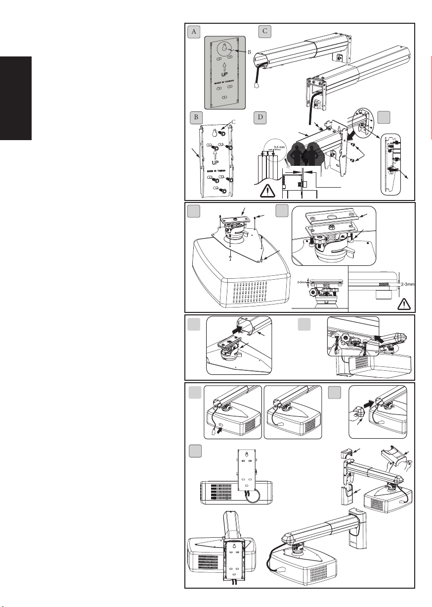
1. Installing the wall bracket
A. Make sure the wall bracket (O) is in the correct position on the wall. Hold the bracket firmly against the wall and mark the holes with a pencil.
Drill holes at the marked points. The holes in a masonry wall should be 10mm (0.39”) in diameter and 55mm deep (2.17”). Use a hammer to
drive the plastic plugs (B) into the holes.
The holes in a wooden wall should be 4.5mm (0.17”) in diameter and 55m (2.17”) deep.
B. Use the self-tapping screws (C) to fix the bracket to the wall.
C. Push the power cord into the front of the projector main support member and pull it out at the back.
D. Insert and secure the socket head screw M6 x L8 (E) in the holes of the projector main support member (P) and the wall bracket (O) by using a
5mm hex wrench (K). It is necessary to leave a gap of 0.5mm for adjustment of the angle after assembly.
E. Before positioning the hinge module (A), secure the socket head screw (G) in the projector main support member (P) to enable the cantilever
support to be in the horizontal direction.
2. Installing the bracket on the bottom of the projector
A. Place the hinge module (A) on the projector. Use the height adjustment collars (I) and screws with fixed washers (H) to fasten it firmly to the
projector.
B. Align the hinge connector (D) with the hole above the hinge module (A). Insert and secure the socket head screw M6 x L12 (F) in the holes of
the hinge module (A) and the hinge connector (D). It is necessary to leave a gap of 2-3 mm for the support to be installed on the cantilever.
3. Installing the bracket on the bottom of the projector.
A. Assembling the hinge module (A) and projector main support (P).
B. After assembling the hinge module (A) and the project main support (P), use the hex wrench (K) to tighten the screws firmly.
P.3
P.4
P.4
P.5
P.6
4. Cable Management
A. Plug the power cord into the projector.
B. Fit the plastic cap (L) on the projector main support member (P).
C. Pass the power cord through the lower plastic cover (N). Fit the upper (M) and lower (N) plastic covers.
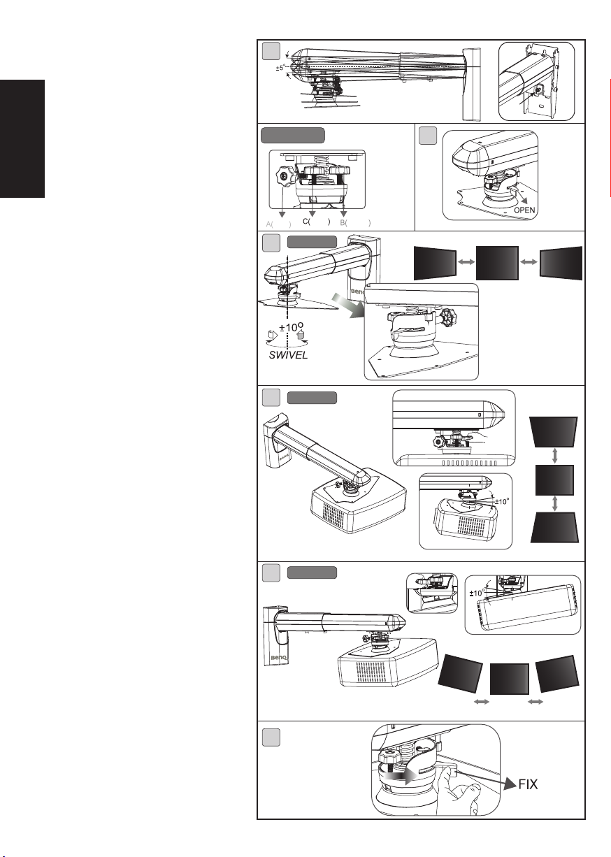
5. Adjusting the required angle
A. By adjusting the tightness of the socket head screw (G) using the hex wrench (K), you can adjust the desired angle of the
projector cantilever. Tighten the socket head screw (E) by using a 5mm hex wrench (K), then replace the upper and lower
plastic caps (M)(N).
B. To adjust the required projection angle push the knobs inwards.
C. The gray knob (A) is for adjusting the rotation angle of the sides of the projected image.
D. The yellow knob (B) is for adjusting the angular displacement of the top and bottom of the projected image.
E. The black knob (C) is for adjusting the horizontal angular displacement of the projected image.
F. Tighten the knobs well and pull them back after making the adjustments.
2 Introduction
P.7
Page 4
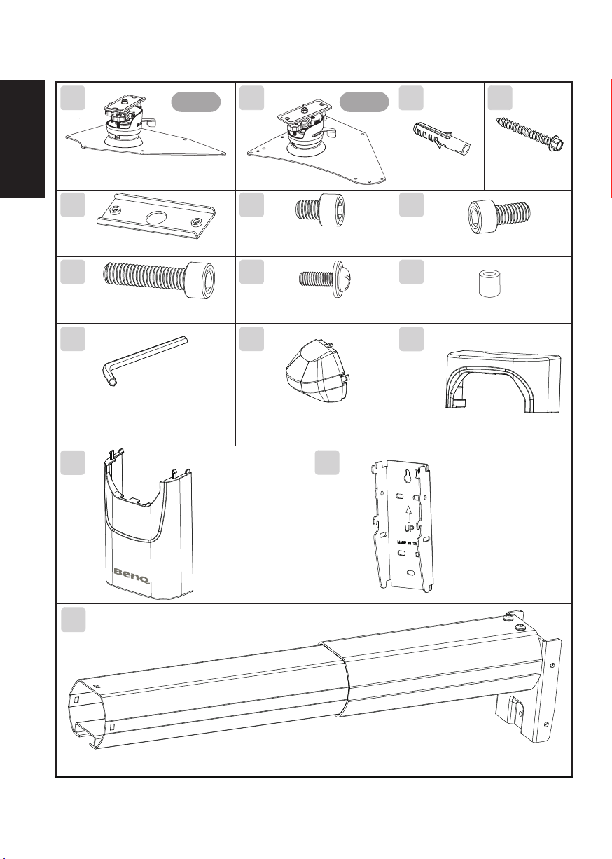
Packaged parts
A A
English
Hinge module__1pc
D
Hinge connector__1pc
G
Socket head screw (M6 x L25)__1pc
K
Hex wrench (Allen Key) (5mm)__1pc
N
Connection
plate A
Connection
E
Socket head screw (M6 x L8)__4pcs
H
Screw with fixed washer__4pcs
L
Cap for projector main support
member__1pc
O
plate B
B
Self-tapping screw
Plastic plug__6pcs
__6pcs
F
Socket head screw (M6 x L12)__2pcs
I
Height adjustment collar__4pcs
M
Upper plastic cover__1pc
C
P
3 Packaged parts
Lower plastic cover__1pc
Wall bracket__1pc
Projector main support member__1pc
Page 5
Required Tools
English
1. Power drill 2. Drill bit 3. Hammer
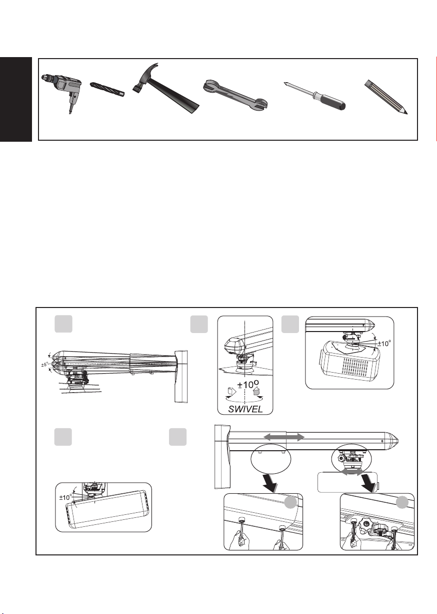
Angle Adjustment
1. Adjust the mounting bracket arm of the projector to ±5°.
2. Adjust the rotation angle of the sides of the projected image.
3. Adjust the angular displacement of the top and
the bottom of the projected image.
1
4. Spanner: 8mm / 10mm
4. Adjust the horizontal angular movement of the projected image.
5. Adjust the projection distance: (A) Move the projector bracket.
5. Cross (Phillips) screwdriver
(B) or adjust the projection distance.
2 3
6. Pencil
4
4 Required Tools/Specifications/Size/Angle adjustment
5
B
A
Page 6
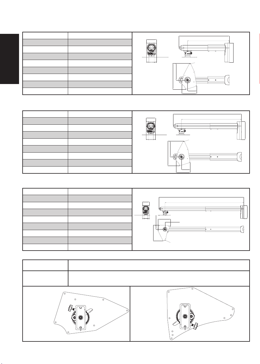
Specifications
Ultra Short Throw Wall Mount
(P/N 5J.J3A10.001)
Connection plate A
Material
English
Weight
Size (W x H x L)
Maximum distance from wall
Rotation angle
Load
Screw
Tilt angle
Steel/Aluminum alloy
4.1 kg (9.04 lbs)
110 x 215 x 558mm
462mm
+/-10˚
15kg (33.07bs)
M4
+/-10°
Ultra Short Throw Wall Mount
(P/N 5J.J4V10.001)
AConnection plate
Material
Weight
Size (W x H x L)
Maximum distance from wall
Rotation angle
Load
Screw
Tilt angle
Steel/Aluminum alloy
4.4 kg (9.7 lbs)
110 x 215 x 803mm
705mm
+/-10˚
12kg (26.46lbs)
M4
+/-10°
Short Throw Wall Mount
(P/N 5J.J4R10.001 )
BConnection plate
Material
Weight
Size (W x H x L)
Maximum distance from wall
Rotation angle
Load
Screw
Tilt angle
Guide sheet for hole drilling
Connection plate A
Connection plate B
Connection plate A Connection plate B
5 Specifications
Steel/Aluminum alloy
5.1 kg (11.24 lbs)
110 x 215 x 1368mm
1270mm
+/-10˚
12kg (26.46lbs)
M4
+/-10°
Please visit www.benq.com for the latest guide sheet for hole drilling
Mark A ==> MX880UST
Mark B ==> MX850UST / MW851UST
Mark A ==> MP772ST /MP776ST / MP782ST/ MX810ST/ MW811ST/ MX812ST / MX813ST
Mark B ==> MW814ST
Mark C ==> MP780ST/MW860USTi
B
A
A
Lens Direction
B
A
B
A
110mm
110mm
110mm
68mm
254.4mm
200mm
291mm
9-Ø5
187mm
89.6mm
A
B
B
187mm
291mm
163.5mm
Lens Direction
A
C
Max: 462mm Min: 395mm
7-Ø5
100mm
163.5mm
Max: 705mm Min: 510mm
7-Ø5
100mm
Max: 1270mm Min: 830mm
C
558mm
1368mm
803mm
215mm
215mm
215mm
A
C
B
Page 7
Installation Steps
1. Installing the wall bracket
A. Make sure the wall bracket (O) is in the correct position
on the wall. Hold the bracket (O) firmly against the wall
and mark the places for the holes with a pencil.
Drill the holes at the marked points. The holes for a
masonry wall should be 10mm (0.39”) in diameter and
English
55mm deep (2.17”). Use a hammer to drive the plastic
plugs (B) into the holes.
For a wooden wall, drill 4.5mm (0.17”) diameter holes
55m (2.17”) deep.
B. Fasten the bracket to the wall with the self-tapping screws
(C) provided.
C. Push the power cord into the front end of the projector
main support member and pull it out at the back.
D. Insert and secure the socket head screw M6 x L8 (E) in
the holes of the projector main support member (P) and
the wall bracket (O) by using a 5mm hex wrench (K). It is
necessary to leave a gap of 0.5mm for adjustment of the
angle after assembly.
E. Before positioning the hinge module (A), secure the
socket head screw (G) in the projector main support
member (P) to enable the cantilever support to be in the
horizontal direction.
2. Installing the fixing bracket on the bottom
of the projector
A. Place the hinge module (A) on the projector. Use the
height adjustment collars (I) and the screws with fixed
washers (H) to fasten the module firmly to the projector.
B. Align the holes in the hinge connector (D) with those in
the hinge module (A). Insert M6 x 12 (F) socket head
screws into the holes and tighten them with the 5mm hex
wrench (K). Allow 2-3mm clearance for installing the
bracket on the arm.
A
B
O
C
1.
A
C
B
D
E
P
0.5mm
A
B
H
I
E
E
G
D
F
2.
3. Installing the bracket on the bottom of the
projector arm
A. Assemble the hinge module (A) and the projector main
support member (P).
B. After this use the hex wrench (K) to fasten them securely.
4. Cable Management
A. Plug the power cord into the projector.
B. Fit the plastic cap (L) to the end of the projector main
support member (P).
C. Pass the power cord through the lower plastic cover (N)
and then fit the upper (M) and lower (N) plastic covers as
shown.
6 Installation Steps
BA
P
A
3.
A
C
B
L
M
N
M
4.
Page 8
Installation Steps
5. Adjusting the projection angle
A. By adjusting the tightness of the socket head screw (G)
using the hex wrench (K), you can adjust the desired
angle of the projector cantilever. Tighten the socket head
screw (E) by using a 5mm hex wrench (K), then replace
the upper and lower plastic caps (M)(N).
B. Push the knobs forwards to adjust the required projection
English
angle.
C. The gray knob (A) is used to adjust the sideways rotation
angle of the projected image.
D. The yellow knob (B) is used to adjust the angular
displacement of the top and bottom of the projected
image.
E. The black knob (C) is used to adjust the horizontal
angular movement of the projected image.
F. Be sure to push back and tighten the knobs securely after
making any adjustment.
A
Knob color indication
Gray
Knob A (gray)
C
Knob B (yellow)
D
Black
G
B
Yellow
7 Installation Steps
E
F
Knob C (black)
Page 9

安全警告
1.為確保安全,在安裝前,請先詳細閱讀本安裝說明書並遵守內
容,妥善保存本安裝說明書於安全的地方,以便日後參考。
繁體中文
2.因為不正確安裝所導致的任何損害或傷害,明基電通概不負責。
3.本壁掛架之設計為容易安裝及拆卸,若因人為或天然災害:如地
震、颱風... 等,所導致的任何損害或傷害,明基電通概不負責。
4.安裝投影機壁掛架需由專業人員執行安裝。
5.無論安裝或移除本產品,至少需由2人執行, 以避免沈重的物品掉
落造成人員或物品傷害。
6.安裝時請於投影機周圍預留足夠的空間,以確保空氣的流通。
7.為了安全及防止意外發生,安裝前,需檢查牆壁的結構及選擇耐久
性高的適當位置。
8.牆壁需能支撐投影機及壁掛架總重量4倍以上,且需確保有足夠的
強度能承受地震及其它外力的振動。
9.安裝前請先確認壁掛架處周圍的環境:
•避免安裝在溫度或濕度過高及任何會碰觸到水的地方。
•請勿安裝於空調設備的出入口附近及避免大量灰塵及油煙處。
•只能安裝於垂直的牆面,避免傾斜的牆面。
•請勿安裝於振動及撞擊處。
•請勿安裝於強光直射處。
10.請勿自行變更任何零件,勿使用已破損的零件,若有任何問題請
與你的經銷商聯絡。
11.鎖緊螺絲( 切勿以過大的扭力鎖付螺絲,以免造成螺絲斷裂或螺牙
的損害)。
12.壁掛架所能支撐投影機的重量為5J.J3A10.001: 15Kg.(33.07 lbs.)
5J.J4V10.001/5J.J4R10.001:12Kg. (26.46 lbs.) 以下。
13.壁掛架除了懸掛投影機,不可加掛其它物件,並嚴禁人員將其他
物品懸掛在壁掛架上。
14.日後移除投影機及壁掛架時,會在牆壁留下螺絲孔及螺栓,且因長
期使用會在牆壁留下污漬。
8 安全警告
Page 10

概述
繁體中文
包裝零件
安裝時俱備工具
調節角度
1.調整投影機壁掛架手臂為 5°
2.調整投影畫面的側邊的旋轉角度。
3.調整投影畫面的高底角度的位移。
4.調整投影畫面的水平角度的位移。
5.調整投影機與投影畫面的距離:(A)可移動投影機托架。
(B)或調整投影機本體的長度。
規格 /尺寸/孔位對照表
安裝步驟
1.安裝牆版
A.確定牆版(O)在牆壁上正確的位置將牆版(O)靠在牆壁上‚對準牆版的孔位,用鉛筆做出小記號。使用
電鑽在標示位置鑽洞。水泥牆孔洞直徑為10mm(0.39’’)深度為55mm(2.17’’)。
木頭牆孔洞直徑為4.5mm(0.17’’)深度為55mm(2.17’’)使用榔頭將塑膠壁虎(B)打入於牆壁固定。
B.將自攻螺絲(C)打入牆壁。
C.將電源線穿入本體(P)的前端一側,再由尾端將電源線拉出。
D.使用六角版手5mm(K)將內六角螺絲M6xL8(E)穿入主體(P)與鐵片(O)的孔位內固定。須留0.5mm的空隙以便組裝完成後調整角度。
E.放置投影機托架(A)之前,將內六角螺絲(G)固定在主體(P)使其懸臂支架是水平方向。
2.投影機底部安裝支架安裝於投影機上
A.將投影機托架(A)放在投影機上,使用套筒(I)在有固定墊片的螺絲(H)將三者與投影機鎖緊。
B.將托架鐵片(D)對準投影機托架(A)上方的孔位,使用六角版手5mm(K)將內六角螺絲M6xL12(F)穿入投影機托架(A)與托架鐵片(D)
的孔位內固定,須留2-3mm的空隙以便支架安裝於懸臂上。
P.10
P.11
P.11
P.12
P.13
3.投影機底部安裝支架安裝於懸臂上
A.將投影機托架(A)與本體(P)本體組合。
B.組合投影機托架(A)與本體(P)後,使用(K)六角版手將兩者固定。
4.電纜管理
將電源線的插頭插到投影機上
A.
B.將理線蓋(L)蓋到主體(P)上。
C.扳開塑膠蓋下(N )將電源線穿過。再將塑膠蓋上( M ) 塑膠蓋下(N )蓋到投影機懸壁上。
5.調整所需角度
A.使用六角版手(K)調整內六角螺絲(G)的鬆緊度,便可調整所須的投影機懸壁的角度,使用六角版手5mm(K)將內
六角螺絲(E)鎖緊,再蓋上塑膠蓋上下(K)(N)。
B.將把手往前推後,可調整所須的投影角度。
C.A旋鈕(灰色),調整投影畫面的側邊的旋轉角度。
D.B旋鈕(黃色),調整投影畫面的高底角度的位移。
E.C旋鈕(黑色),調整投影畫面的水平角度的位移。
F.調整完所需的角度後再將把手往後推,鎖緊。
9 概述
P.14
Page 11

包裝零件
A A
繁體中文
Hinge module__1pcs
投影機托架___1件
D
Hinge connector__1pcs
托架鐵片___1件
G
Hex bolts (M6xL25)__1pcs
內六角螺絲(M6xL25)___1件
K
Hex key(5mm)__1pcs Cable management cap__1pcs
六角版手(5mm)___1件
N
連接盤 A 連接盤 B
E
Hex bolts(M6 xL8)__4pcs
內六角螺絲(M6 xL8 )___4件
H
Bolts with fixed washer__4pcs
有固定墊片的螺絲___4件
L
理線蓋___1件
O
B
Plastic plug__6pcs
塑膠壁虎___6件
F
Hex bolts (M6xL12)__2pcs
內六角螺絲(M6xL12)___2件
I
Height adjustment pipe__4pcs
套筒___4件
M
upper plastic cap__1pcs
塑膠蓋上___1件
C
Tapping screw__6pcs
自攻螺絲___6件
P
10 包裝零件
lower plastic cap__1pcs
塑膠蓋下___1件
projector main pole__1pcs
wall bracket__1pcs
牆版___1件
本體__1件
Page 12

安裝時俱備工具
繁體中文
1. 電鑽 2. 鑽頭 3. 鎯頭
調節角度
1.調整投影機壁掛架手臂為 5°
2.調整投影畫面的側邊的旋轉角度。
3.調整投影畫面的高底角度的位移。
+
-
1
4. 板手:8mm/ 10 mm
4.調整投影畫面的水平角度的位移。
5.調整投影機與投影畫面的距離:(A)可移動投影機托架
(B)或調整投影機本體的長度。
5. 十字型螺絲起子
2 3
6. 鉛筆
4
11 安裝時俱備工具/規格/尺寸/調節角度
5
B
A
Page 13

規格
超短焦牆壁固定吊架 料號: 5J.J3A10.001
連接盤 A
材質
繁體中文
重量
尺寸(寬*高*長)
離牆面最大距離
旋轉角度
載重
螺絲
傾斜角度
鋼材/鋁合金
4.1kg (9.04lbs)
110x215x558 mm
462mm
+/-10˚
15kg(33.07lbs)
M4
+/-10°
超短焦牆壁固定吊架 料號:5J.J4V10.001
連接盤
材質
重量
尺寸(寬*高*長)
離牆面最大距離
旋轉角度
載重
螺絲
傾斜角度
A
鋼材/鋁合金
4.4kg (9.7lbs)
110x215x803 mm
705mm
+/-10˚
12kg(26.46lbs)
M4
+/-10°
短焦牆壁固定吊架 料號: 5J.J4R10.001
連接盤
材質
重量
尺寸(寬*高*長)
離牆面最大距離
旋轉角度
載重
螺絲
傾斜角度
B
鋼材/鋁合金
5.1kg (11.24lbs)
110x215x1368 mm
1270mm
+/-10˚
12kg(26.46lbs)
M4
+/-10°
110mm
尺寸
110mm
尺寸
110mm
尺寸
68mm
254.4mm
200mm
291mm
9-Ø5
291mm
187mm
89.6mm
187mm
163.5mm
163.5mm
7-Ø5
100mm
558mm
Max:462mm Min:395mm
215mm
7-Ø5
100mm
803mm
Max:705mm Min:510mm
215mm
1368mm
Max:1270mm Min:830mm
215mm
孔位對照表
連接盤 A
連接盤 B
連接盤 A 連接盤 B
12 規格
Mark A ==> MX880UST
Mark B ==> MX850UST / MW851UST
Mark A ==> MP772ST /MP776ST / MP782ST/ MX810ST/ MW811ST/ MX812ST / MX813ST
Mark B ==> MW814ST
Mark C ==> MP780ST/MW860USTi
B
A
A
Lens Direction
B
A
B
A
最新型號孔位對照表請上www.benq.com查詢
Lens Direction
A
C
B
C
A
C
B
A
B
Page 14

安裝步驟
A
C
1.安裝牆版
A.確定牆版(O)在牆壁上正確的位置將牆版(O)靠在
牆壁上,對準牆版的孔位,用鉛筆做出小記號。
繁體中文
使用電鑽在標示位置鑽洞。水泥牆孔洞直徑為
10mm( 0.39”)深度為55mm( 2.17”)。
木頭牆孔洞直徑為4.5mm( 0.17”)深度為55mm
( 2.17”)使用榔頭將塑膠壁虎(B)打入於牆壁固定。
B.將自攻螺絲(C)打入牆壁。
C.將電源線穿入本體(P)的前端一側,再由尾端將電源
線拉出。
D.使用六角版手5mm(K)將內六角螺絲M6xL8(E)穿入
主體(P)與鐵片(O)的孔位內固定。須留0.5mm的空
隙以便組裝完成後調整角度。
E.放置投影機托架(A)之前,將內六角螺絲(G)固定在主
體(P)使其懸臂支架是水平方向。
2.投影機底部安裝支架安裝於投影機上
A.將投影機托架(A)放在投影機上,使用套筒(I)在有固定
墊片的螺絲(H)將三者與投影機鎖緊。
B.將托架鐵片(D)對準投影機托架(A)上方的孔位,使用
六角版手5mm(K)將內六角螺絲M6xL12(F)穿入投影機
托架(A)與托架鐵片(D)的孔位內固定,須留2-3mm的
空隙以便支架安裝於懸臂上。
3.投影機底部安裝支架安裝於懸臂上
A.將投影機托架(A)與本體(P)本體組合。
B.組合投影機托架(A)與本體(P)後,使用(K)六角版手
將兩者固定。
B
B
O
1.
A
D
C
E
P
0.5mm
A
B
H
I
E
E
G
D
F
2.
A
P
A
B
4.電纜管理
將電源線的插頭插到投影機上
A.
B.將理線蓋(L)蓋到主體(P)上。
C.扳開塑膠蓋下(N )將電源線穿過。再將塑膠蓋上( M )
塑膠蓋下(N )蓋到投影機懸壁上。
13 安裝步驟
3.
A
C
B
L
M
N
M
4.
Page 15

安裝步驟
5.調整所需角度
A.使用六角版手(K)調整內六角螺絲(G)的鬆緊度,
便可調整所須的投影機懸壁的角度,使用六角版手
5mm(K)將內六角螺絲(E)鎖緊,再蓋上塑膠蓋上下
(K)(N)。
繁體中文
B.將把手往鬆開後,可調整所須的投影角度。
C.A旋鈕(灰色),調整投影畫面的側邊的旋轉角度。
D.B旋鈕(黃色),調整投影畫面的高底角度的位移。
E.C旋鈕(黑色),調整投影畫面的水平角度的位移。
F.調整完所需的角度後再將把手往後推、鎖緊。
A
旋鈕顏色標示
灰色
A旋鈕(灰色)
C
B旋鈕(黃色)
D
黑色
G
B
黃色
14 安裝步驟
E
F
C旋鈕(黑色)
Page 16

Warnung
1. Bitte lesen Sie die Anweisungen in dieser Installationsanleitung vor der Installation
aufmerksam durch und halten Sie sich stets daran. Bewahren Sie die Anleitung auf,
Deutsch
damit Sie später darin nachlesen können.
2. Die BenQ Corporation haftet nicht bei Schäden oder Verletzungen, die durch falsche
Installation entstehen.
3. Die Wandhalterung wurde so entwickelt, das sie besonders leicht angebracht und
abgenommen werden kann. Die BenQ Corporation haftet nicht bei Schäden oder
Verletzungen, die durch menschliche Eingriffe oder durch Naturkatastrophen
verursacht werden; beispielsweise Erdbeben oder Stürme.
4. Die Projektor-Wandhalterung darf nur von professionellen Fachkräften installiert
werden.
5. Bei der Installation und beim Abnehmen der Halterung sind mindestens zwei
Personen erforderlich, damit es nicht zu Verletzungen und nicht zu Sachschäden
durch schwere, fallende Gegenstände kommt.
6. Damit die ordentliche Belüftung nicht behindert wird, installieren Sie den Projektor
so, dass ein ausreichend großer Abstand zwischen dem Gerät und Wand und Decke
verbleibt.
7. Um eine sichere Installation zu gewährleisten und Unfälle zu verhindern, überprüfen
Sie die Wand im Voraus und wählen eine besonders robuste Stelle.
8. Die Wand sollte so robust sein, dass sie mindestens das Vierfache des
Gesamtgewichtes der Kombination aus Projektor und Wandhalterung tragen kann.
Zusätzlich sollte die Wand auch gegen starke Vibrationen resistent sein, die
beispielsweise bei Erdbeben auftreten können.
9. Nehmen Sie die Umgebung der Montagestelle vor der Installation in Augenschein.
• Installieren Sie das Gerät nicht an Stellen, an denen hohe Temperaturen herrschen
und/oder an denen es feucht ist.
• Installieren Sie das Gerät nicht in der Nähe von Klimaanlagen oder
Lüftungsöffnungen und nicht an staubigen oder fettigen Stellen.
• Das Produkt darf nur an vertikalen, nicht an geneigten Wänden installiert werden.
• Installieren Sie das Produkt nicht an Orten, die Vibrationen oder Stößen ausgesetzt
sind.
• Halten Sie den Projektor von direkter Sonneneinstrahlung fern.
10. Tauschen Sie keinerlei Teile aus, verwenden Sie keine beschädigten Teile. Bitte
wenden Sie sich bei Fragen an Ihren Händler.
11. Ziehen Sie Schrauben fest, jedoch nicht übermäßig stark an – andernfalls können die
Schrauben abreißen oder die Gewinde beschädigt werden.
12. Die Wandhalterung kann für Projektoren mit einem Gewicht von bis zu
5J.J3A10.001:15 Kg 5J.J4V10.001/5J.J4R10.001:12Kg eingesetzt werden.
13. Die Wandhalterung darf nicht mit zusätzlichem Gewicht belastet werden. Bringen Sie
nichts daran an, hängen Sie nichts daran.
14. Bitte beachten Sie, dass die Schraubenlöcher auch nach dem Abnehmen der
Wandhalterung in der Wand verbleiben und dass bei längerem Einsatz Spuren an der
Wand zurückbleiben können.
15 Warnung
Page 17

Einleitung
Deutsch
Teile im Lieferumfang
Benötigte Werkzeuge
Winkeleinstellung
1. Stellen Sie den Wandhalterungsarm des Projektors auf ±5 ° ein.
2. Passen Sie den Drehwinkel an die Seiten des projizierten Bildes an.
3. Justieren Sie die Winkelverstellung gemäß des oberen und unteren Randes des projizierten Bildes.
4. Stellen Sie den horizontalen Winkelversatz des projizierten Bildes ein.
5. Abstand zwischen Projektor und projiziertem Bild anpassen: (A) Verschieben Sie die Projektorhalterung.
Technische Daten/Größe/Bohrschablone
Installationsschritte
1. Wandhalterung installieren
A. Achten Sie darauf, dass die Wandhalterung (O) an der richtigen Stelle an der Wand sitzt. Drücken Sie die Halterung fest gegen die Wand,
markieren Sie die Bohrlöcher mit einem Stift. Bohren Sie Löcher an den markierten Stellen. In Mauerwerk sollten Löcher mit einem
Durchmesser von 10 mm und einer Tiefe von 55 mm gebohrt werden. Klopfen Sie die Kunststoffdübel (B) mit einem Hammer in die Löcher.
Bei Holzwänden sollten Löcher mit einem Durchmesser von 4,5 mm und einer Tiefe von 55 mm gebohrt werden.
B. Fixieren Sie die Halterung mit Blechschrauben (C) an der Wand.
C. Führen Sie das Netzkabel von vorne nach hinten durch die Halterung.
D. Führen Sie die Innensechskantschraube (M6 x L8) (E) durch die Öffnungen in der Haupt-Projektorhalterung (P) und in der Wandhalterung
(O). Ziehen Sie die Schraube anschließend mit dem 5-mm-Sechskantschlüssel (K) an. Dabei muss zur Winkeleinstellung nach der Montage ein
Spalt von 0,5 mm verbleiben.
E. Bevor Sie das Scharniermodul (A) anbringen, fixieren Sie die Innensechskantschraube (G) an der Haupt-Projektorhalterung (P), damit die
Auslegerhalterung horizontal verläuft.
P.17
P.18
P.18
(B) Alternativ passen Sie den Projektionsabstand händisch an.
P.19
P.20
2. Halterung am Boden des Projektors anbringen
A. Setzen Sie das Scharniermodul (A) auf den Projektor auf. Anschließend mit Höhenverstellungshülsen (I) und Schrauben mit fest angebrachten
Unterlegscheiben (H) am Projektor fixieren.
B. Bringen Sie den Scharnierverbinder (D) mit der Aussparung oberhalb des Scharniermoduls (A) in Flucht. Führen Sie die Innensechs-
kantschraube (M6 x L12) (F) in die Öffnungen im Scharniermodul (A) und dem Scharnierverbinder (D). Anschließend gut anziehen. Es ist
notwendig, dass ein Spalt von 2 – 3 mm verbleibt, damit die Halterung am Ausleger angebracht werden kann.
3. Halterung am Boden des Projektors anbringen
A. Scharniermodul (A) und Haupt-Projektorhalterung (P) zusammensetzen.
B. Nach Montage des Scharniermoduls (A) und der Haupt-Projektorhalterung (P) ziehen Sie die Schrauben mit dem Sechskantschlüssel (K) fest
an.
4. Kabelführung
A. Verbinden Sie das Netzkabel mit dem Projektor.
Kappe für Haupt-Projektorhalterung
B. Setzen
C. Führen Sie das Netzkabel durch die Untere Kunststoffabdeckung (N). Bringen Sie die obere (M) und die untere (N) Kunststoffabdeckung an.
5. Erforderlichen Winkel einstellen
A. Durch Anziehen oder Lösen der Innensechskantschraube (G) mit dem Sechskantschlüssel (K) können Sie den gewünschten
Winkel des Projektorauslegers einstellen. Ziehen Sie die Innensechskantschraube (G) mit einem 5-mm-Sechskantschlüssel (K)
an, setzen Sie dann die oberen und unteren Kunststoffkappen (M) (N) auf.
B. Zum Einstellen des erforderlichen Projektionswinkels drücken Sie den Knopf nach innen.
C. Der graue Knopf (A) dient der Einstellung des Drehwinkels zu den Seiten des projizierten Bildes.
D. Der gelbe Knopf (B) dient der Winkeleinstellung zum oberen und unteren Rand des projizierten Bildes hin.
D. Der schwarze Knopf (C) dient der Einstellung des horizontalen Winkelversatzes des projizierten Bildes.
F. Ziehen Sie die Knöpfe gut an, ziehen Sie die Knöpfe nach Abschluss der Einstellungen wieder heraus.
16 Einleitung
(L) auf die Haupt-Projektorhalterung (P) auf.
P.21
Page 18

Teile im Lieferumfang
A A
Deutsch
Scharniermodul, 1 x
D
Scharnierverbinder, 1 x
G
Innensechskantschraube (M6 x L25), 1 x
K
Sechskantschlüssel (5 mm), 1 x
N
Verbindungsplatte A Verbindungsplatte B
E
Innensechskantschraube (M6 x L8), 4 x
H
Schraube mit fest angebrachter
Unterlegscheibe, 4 x
L
Kappe für Haupt-Projektorhalterung, 1 x
O
B
Kunststoffdübel, 6 xCBlechschraube, 6 x
F
Innensechskantschraube (M6 x L12), 2 x
I
Höhenverstellungshülse, 4 x
M
Obere Kunststoffabdeckung, 1 x
P
17 Teile im Lieferumfang
Untere Kunststoffabdeckung, 1 x
Haupt-Projektorhalterung, 1 x
Wandhalterung, 1 x
Page 19

Benötigte Werkzeuge
Deutsch
1. Bohrmaschine 2. Bohrer 3. Hammer
4. Schraubenschlüssel: 8 mm / 10 mm
Winkeleinstellung
1. Stellen Sie den Wandhalterungsarm des Projektors auf ±5 ° ein.
2. Passen Sie den Drehwinkel an die Seiten des projizierten Bildes an.
3. Justieren Sie die Winkelverstellung gemäß des oberen und unteren
Randes des projizierten Bildes.
1
4. Stellen Sie den horizontalen Versatz des projizierten Bildes ein.
5. Projektionsabstand anpassen: (A) Verschieben Sie die Projektorhalterung.
2 3
Drehen
5. Kreuzkopfschraubendreher
(B) Alternativ passen Sie den
Projektionsabstand händisch an.
6. Stift
4
18 Benötigte Werkzeuge/Technische Daten/Größe/Winkeleinstellung
5
B
A
Page 20

Specifications
Ultrakurzdistanzprojektionswandhalterung
(5J.J3A10.001)
Verbindungsplatte A
Material
Deutsch
Gewicht
Abmessungen (B x H x L)
Maximaler Wandabstand
Drehwinkel
Last
Schraube
Neigungswinkel
Stahl/Aluminiumlegierung
4,1 kg
110 x 215 x 558 mm
462 mm
+/-10˚
15 kg
M4
+/-10°
Ultrakurzdistanzprojektionswandhalterung
(5J.J4V10.001)
AVerbindungsplatte
Material
Gewicht
Abmessungen (B x H x L)
Maximaler Wandabstand
Drehwinkel
Last
Schraube
Neigungswinkel
Stahl/Aluminiumlegierung
4,4 kg
110 x 215 x 803 mm
705 mm
+/-10˚
12 kg
M4
+/-10°
Ultrakurzdistanzprojektionswandhalterung
(5J.J4R10.001)
BVerbindungsplatte
Material
Gewicht
Abmessungen (B x H x L)
Maximaler Wandabstand
Drehwinkel
Last
Schraube
Neigungswinkel
Bohrschablone
Verbindungsplatte A
Verbindungsplatte B
Verbindungsplatte A Verbindungsplatte B
19 Technische Daten
Stahl/Aluminiumlegierung
5,1 kg
110 x 215 x 1.368 mm
1270 mm
+/-10˚
12 kg
M4
+/-10°
Aktuellste Bohrschablonen finden Sie unter www.benq.com.
Marke A ==> MX880UST
Marke B ==> MX850UST / MW851UST
Marke A ==> MP772ST /MP776ST / MP782ST/ MX810ST/ MW811ST/ MX812ST / MX813ST
Marke B ==> MW814ST
Marke C ==> MP780ST/MW860USTi
B
A
A
Objektivrichtung
B
A
B
A
110 mm
110 mm
110 mm
68 mm
254,4 mm
200 mm
291 mm
9-Ø5
291 mm
187 mm
89,6 mm
A
B
Objektivrichtung
B
A
C
187 mm
163,5 mm
100 mm
558 mm
Max: 462 mm Min.: 395 mm
7-Ø5
100 mm
163,5 mm
Max: 705 mm Min.: 510 mm
7-Ø5
1368 mm
Max: 1.270 mm Min.: 830 mm
C
803 mm
215 mm
215 mm
215 mm
A
C
B
Page 21

Installationsschritte
1. Wandhalterung installieren
A. Achten Sie darauf, dass die Wandhalterung (O) an der
richtigen Stelle an der Wand sitzt. Drücken
Wandhalterung (O) fest gegen die Wand, markieren Sie
die Bohrlöcher mit einem Stift.
Bohren Sie Löcher an den markierten Stellen. In
Mauerwerk sollten Löcher mit einem Durchmesser von
Deutsch
10 mm und einer Tiefe von 55 mm gebohrt werden.
Klopfen Sie die Kunststoffdübel (B) mit einem Hammer
in die Löcher.
Bei Holzwänden sollten Löcher mit einem Durchmesser
von 4,5 mm und einer Tiefe von 55 mm gebohrt werden.
B. Fixieren Sie die Halterung mit den mitgelieferten
Blechschrauben (C) an der Wand.
C. Führen Sie das Netzkabel von vorne nach hinten durch
die Halterung.
D. Führen Sie die Innensechskantschraube (M6 x L8) (E)
durch die Öffnungen in der Haupt-Projektorhalterung
(P) und in der Wandhalterung (O). Ziehen Sie die
Schraube anschließend mit dem
5-mm-Sechskantschlüssel (K) an. Dabei muss zur
Winkeleinstellung nach der Montage ein Spalt von 0,5
mm verbleiben.
E. Bevor Sie das Scharniermodul (A) anbringen, fixieren Sie
die Innensechskantschraube (G) an der
Haupt-Projektorhalterung (P), damit die Auslegerhalterung horizontal verläuft.
2. Fixierhalterung am Boden des Projektors
anbringen
A. Setzen Sie das Scharniermodul (A) auf den Projektor auf.
Fixieren Sie das Modul mit Höhenverstellungshülsen (I)
und Schrauben mit fest angebrachten Unterlegscheiben
(H) am Projektor.
B. Bringen Sie den Scharnierverbinder (D) mit der
Aussparung oberhalb des Scharniermoduls (A) in Flucht.
Führen Sie die Innensechskantschraube (M6 x L12) (F) in
die Öffnungen im Scharniermodul (A) und dem
Scharnierverbinder (D). Anschließend gut anziehen. Es
ist notwendig, dass ein Spalt von 2 – 3 mm verbleibt,
damit die Halterung am Ausleger angebracht werden
kann.
A
B
O
C
1.
A
C
B
D
,
E
P
0,5 mm
A
B
H
I
E
E
G
D
F
2.
3. Halterung am Boden des Projektorarms
anbringen
A. Setzen Sie Scharniermodul (A) und
Haupt-Projektorhalterung (P) zusammen.
B. Ziehen Sie die Schrauben anschließend mit dem
Sechskantschlüssel (K) fest an.
4. Kabelführung
A. Verbinden Sie das Netzkabel mit dem Projektor.
Kappe für Haupt-Projektorhalterung
B. Setzen
Haupt-Projektorhalterung (P) auf.
C. Führen Sie das Netzkabel durch die Untere Kunststoffab-
deckung (N), bringen Sie anschließend die obere (M)
und untere (N) Kunststoffabdeckung wie abgebildet an.
20 Installationsschritte
(L) auf die
BA
P
A
3.
A
C
B
L
M
N
M
4.
Page 22

Installationsschritte
5. Projektionswinkel einstellen
A. Durch Anziehen oder Lösen der Innensechskantschraube
(G) mit dem Sechskantschlüssel (K) können Sie den
gewünschten Winkel des Projektorauslegers einstellen.
Ziehen Sie die Innensechskantschraube (E) mit einem
5-mm-Sechskantschlüssel (K) an, setzen Sie dann die
oberen und unteren Kunststoffkappen (M) (N) auf.
Deutsch
B. Schieben Sie die Knöpfe zum Einstellen des gewünschten
Projektionswinkels nach vorne.
C. Der graue Knopf (A) wird zum Anpassen des seitlichen
Rotationswinkels des projizierten Bildes eingesetzt.
D. Der gelbe Knopf (B) dient der Winkeleinstellung zum
oberen und unteren Rand des projizierten Bildes hin.
E. Der schwarze Knopf (C) dient der Einstellung des
horizontalen Winkelversatzes des projizierten Bildes.
F. Vergessen Sie nicht, die Knöpfe nach Einstellungen
zurückzuschieben und anzuziehen.
A
Knopf-Farbkennzeichnung
grau
Knopf A (grau)
C
Drehen
Knopf B (gelb)
D
schwarz
G
B
Öffen
gelb
21 Installationsschritte
Knopf C (schwarz)
E
F
Fixieren
Page 23

Avertissement
1. Veuillez lire attentivement les instructions figurant dans cette notice et observez-les
Français
scrupuleusement pour procéder à l'installation, et conservez-les pour vous y référer
ultérieurement.
2. La société BenQ décline toute responsabilité pour tout dommage ou blessure résultant d’une
installation incorrecte.
3. Le support mural est conçu pour faciliter le montage et le démontage. La société BenQ décline
toute responsabilité pour tout dommage ou blessure du fait d'une intervention humaine ou de
causes naturelles, telles qu'un tremblement de terre ou un typhon.
4. Ce support de montage pour projecteur doit être installé exclusivement par des professionnels
qualifiés.
5. Deux personnes au minimum sont à prévoir pour l’installation et la dépose de ce support afin
d’éviter tout risque de blessure ou de dommage matériel susceptibles de résulter de la chute
d'objets lourds.
6. Pour garantir une ventilation appropriée, prévoir un espace suffisant entre le projecteur et le
mur et le plafond.
7. Pour garantir la sécurité de l’installation et prévenir des accidents, vérifier la structure murale
et choisir un emplacement à la fois solide et stable.
8. Le mur doit être suffisamment résistant pour soutenir au moins quatre fois le poids total du
projecteur et le support de montage mural. Il doit également être suffisamment solide pour
supporter la force des vibrations induites par les tremblements de terre ou d'autres
phénomènes.
9. Contrôler le cadre environnant de l’emplacement de montage avant de procéder à
l'installation.
• Ne pas installer l’équipement dans un emplacement exposé à des températures ou une
humidité élevées et éviter les endroits humides.
• Ne pas installer l'équipement à proximité d'un climatiseur ou de bouches d'aération, ou
dans un emplacement poussiéreux ou exposé à des projections d’huile.
• Ce produit doit être installé exclusivement sur un mur vertical et non pas en biais.
• Ne pas installer l’équipement dans un emplacement soumis à des vibrations ou des chocs.
• Maintenir le projecteur à l’écart de la lumière directe du soleil.
10. Ne pas remplacer de pièces ni utiliser des pièces endommagées. Contacter le revendeur ou
distributeur pour toute question.
11. Serrer les vis convenablement mais sans excès pour éviter leur rupture ou un endommagement
des filets.
12. Le support de montage mural peut soutenir un projecteur d'un poids maximal de
5J.J3A10.001:15 Kg ou 33,07 livres. 5J.J4V10.001/5J.J4R10.001:12 Kg ou 26,46 livres.
13. Aucune autre charge supplémentaire ne doit être ajoutée sur le support de montage mural.
Aucun objet ne doit être fixé ou accroché au support.
14. Les trous pour les vis resteront sur le mur après dépose du support de montage du projecteur
et des marques peuvent également résulter d'un usage prolongé.
22 Avertissement
Page 24

Introduction
Français
Pièces incluses
Outils requis
Réglage de l’angle
1. Réglez le bras de la patte de fixation du projecteur à 5°.
2. Réglez l’angle de rotation des côtés de l’image projetée.
3. Réglez le décalage angulaire du haut et du bas de l'image projetée.
4. Réglez le mouvement angulaire horizontal de l'image projetée.
5. Réglez la distance entre le projecteur et l’image projetée: (A) Déplacez le support du projecteur.
(B) ou réglez la distance de projection.
Spécifications/Taille/Fiche de guidage pour perçage de trous
Étapes d’installation
1. Installer le support mural
A. Assurez-vous que le support mural (O) se trouve à la position correcte sur le mur. Maintenez le support fermement contre le mur et marquez
l’emplacement des trous avec un crayon.
Percez les trous au niveau des repères marqués. Les trous pour un mur en maçonnerie doivent présenter un diamètre de 10 mm (0,39”) et une
profondeur de 55 mm (2,17”). Utilisez un marteau pour enfoncer les chevilles en plastique (B) dans les trous.
Les trous dans une cloison en bois doivent présenter un diamètre de 4,5 mm (0,17”) et une profondeur de 55 mm (2,17”).
B. Utilisez les vis autotaraudeuses (C) pour fixer le support sur le mur.
C. Repoussez le cordon d’alimentation dans la face avant de l’élément de support principal du projecteur et tirez-le pour le sortir à l’arrière.
D. Engagez la vis six pans creux M6 x L8 (E) dans les trous de l’élément de support principal de projecteur (P) et du support mural (O) et serrez-la
à l’aide de la clé six pans mâle de 5 mm (K). Un jeu de 0,5 mm est à prévoir pour le réglage de l’angle après le montage.
E. Avant de positionner le module de charnière (A), serrez la vis six pans creux (G) sur l’élément de support principal de projecteur (P) pour
amener le support de suspension dans le sens horizontal.
2. Installer la patte sur le bas du projecteur
A. Mettez en place le module de charnière (A) sur le projecteur. Utilisez les bagues de réglage en hauteur (I) et les vis avec les rondelles fixes (H)
pour fixer le module sur le projecteur.
B. Alignez le raccord de charnière (D) avec le trou au-dessus du module de charnière (A). Engagez et serrez la vis six pans creux M6 x L12 (F) dans
les trous du module de charnière (A) et du raccord de charnière (D). Un jeu de 2 à 3 mm est à prévoir pour l’installation du support sur la
suspension.
3. Installer la patte sur le bas du projecteur
A. Assembler le module de charnière (A) et l’élément de support principal de projecteur (P)
B. Après avoir assemblé le module de charnière (A) et l’élément de support principal de projecteur (P); utilisez la clé six pans mâle (K) pour serrer
convenablement les vis.
4. Gestion du câble
A. Raccordez le cordon d'alimentation au projecteur.
B. Montez le c
C. Faites passer le cordon d’alimentation par le cache inférieur en plastique (N). Montez les caches supérieur (M) et inférieur (N) en plastique.
ache pour élément de support
(L) sur l’élément de support principal du projecteur (P).
P.24
P.25
P.25
P.26
P.27
5. Régler l'angle de projection
A. En ajustant le serrage de la vis six pans creux (G) à l’aide de la clé six pans mâle (K), vous pouvez régler à votre convenance
l’angle de suspension du projecteur. Serrez la vis six pans creux (E) à l’aide de la clé six pans mâle de 5 mm (K) puis remettez en
place les caches supérieur et inférieur en plastique (M)(N).
B. Pour réglez l’angle de projection, poussez les boutons vers l’intérieur.
C. Le bouton gris (A) sert à régler l’angle de rotation des côtés de l’image projetée.
D. Le bouton jaune (B) sert à régler le décalage angulaire du haut et du bas de l’image projetée.
E. Le bouton noir (C) sert à régler le mouvement angulaire horizontal de l’image projetée.
F. Serrez bien les boutons et ramenez-les en position après avoir effectué les réglages.
23 Introduction
P.28
Page 25

Pièces incluses
A A
Français
Module de charnière__1 pc
D
Raccord de charnière__1 pc
G
Vis six pans creux (M6 x L25)__1 pc
K
Clé six pans mâle (Allen) (5mm)__1 pc
N
Platine de
liaison A
E
Vis six pans creux (M6 x L8)__4 pcs
H
Vis avec rondelle fixe__4 pcs
L
Cache pour élément de support
principal de projecteur__1 pc
O
Platine de
liaison B
B
Cheville en plastique
__6 pcs
F
Vis six pans creux (M6 x L12)__2 pcs
I
Bague de réglage en hauteur__4 pcs
M
Cache supérieur en plastique__1 pc
C
Vis autotaraudeuse
__6 pcs
P
24 Pièces incluses
Cache inférieur en
plastique__1 pc
Support mural__1 pc
Élément de support principal de projecteur__1 pc
Page 26

Outils requis
Français
1.
Perceuse électrique
2. Foret 3. Marteau
Réglage de l’angle
1. Réglez le bras de la patte de fixation du projecteur à ± 5°.
2. Réglez l’angle de rotation des côtés de l’image projetée.
3. Réglez le décalage angulaire du haut et du bas de l'image projetée.
4. Clé plate 8 mm / 10 mm
4. Réglez le mouvement angulaire horizontal de l'image projetée.
5. Réglez la distance de projection. (A) Déplacez le support du projecteur.
5. Tournevis cruciforme
(B) ou réglez la distance de projection.
6. Crayon
1
4
25 Outils requis/Spécifications/Taille/Réglage de l'angle
2 3
PIVOTEMENT
5
B
A
Page 27

Spécifications
Montage mural pour ultra-courte focale
(P/N 5J.J3A10.001)
Platine de liaison A
Matériau
Français
Poids
Dimensions (L x H x l)
Distance maximale du mur
Angle de rotation
Charge
Vis
Angle d’inclinaison
Acier/alliage d’aluminium
4,1 kg (9,04 livres)
110 x 215 x 558mm
462mm
+/-10˚
15 kg (33,07 livres)
M4
+/-10°
Montage mural pour ultra-courte focale
(P/N 5J.J4V10.001)
APlatine de liaison
Matériau
Poids
Dimensions (L x H x l)
Distance maximale du mur
Angle de rotation
Charge
Vis
Angle d’inclinaison
Acier/alliage d’aluminium
4,4 kg (9,7 livres)
110 x 215 x 803mm
705mm
+/-10˚
12 kg (26,46 livres)
M4
+/-10°
Montage mural pour ultra-courte focale
(P/N 5J.J4R10.001)
BPlatine de liaison
Matériau
Poids
Dimensions (L x H x l)
Distance maximale du mur
Angle de rotation
Charge
Vis
Angle d’inclinaison
Fiche de guidage pour perçage de trous
Platine de liaison A
Platine de liaison B
Platine de liaison A Platine de liaison B
26 Spécifications
Acier/alliage d’aluminium
5,1 kg (11,24 livres)
110 x 215 x 1 368mm
1270mm
+/-10˚
12 kg (26,46 livres)
M4
+/-10°
Consulter le site www.benq.com pour la fiche de
guidage mise à jour pour le perçage des trous.
Repère A ==> MX880UST
Repère B ==> MX850UST / MW851UST
Repère A ==> MP772ST /MP776ST / MP782ST/ MX810ST/ MW811ST/ MX812ST / MX813ST
Repère B ==> MW814ST
Repère C ==> MP780ST/MW860USTi
B
A
A
Direction de lentille
B
A
B
A
110mm
110mm
110mm
68mm
254,4mm
200mm
291mm
9-Ø5
291mm
187mm
89,6mm
A
B
Direction de lentille
A
C
B
187mm
163,5mm
163,5mm
7-Ø5
100mm
558mm
Maxi: 462mm Mini: 395mm
7-Ø5
100mm
803mm
Maxi: 705mm Mini: 510mm
1368mm
Maxi: 1 270mm Mini: 830mm
C
215mm
215mm
215mm
A
C
B
Page 28

Étapes d’installation
1. Installer le support mural
A. Assurez-vous que le support mural (O) se trouve à la
position correcte sur le mur. Maintenez le support mural
(O) fermement contre le mur et marquez l’emplacement
des trous avec un crayon.
Percez les trous au niveau des repères marqués. Les trous
pour un mur en maçonnerie doivent présenter un
Français
diamètre de 10 mm (0.39”) et une profondeur de 55 mm
(2,17”). Utilisez un marteau pour enfoncer les chevilles
en plastique (B) dans les trous.
Pour une cloison en bois, percez des trous de 4,5 mm
(0,17”) de diamètre et de 55 mm (2,17”) de profondeur.
B. Fixez le support sur le mur avec les vis autotaraudeuses
(C) fournies.
C. Repoussez le cordon d’alimentation dans l’extrémité
avant de l’élément de support principal du projecteur et
tirez-le pour le sortir à l’arrière.
D. Engagez la vis six pans creux M6 x L8 (E) dans les trous
de l’élément de support principal de projecteur (P) et du
support mural (O) et serrez-la à l’aide de la clé six pans
mâle de 5 mm (K). Un jeu de 0,5 mm est à prévoir pour
le réglage de l’angle après le montage.
E. E. Avant de positionner le module de charnière (A),
serrez la vis six pans creux (G) sur l’éélément de support
principal de projecteur (P) pour amener le support de
suspension dans le sens horizontal.
2. Installer la patte de fixation sur le bas du
projecteur
A. Mettez en place le module de charnière (A) sur le
projecteur. Utilisez les bagues de réglage en hauteur (I) et
les vis avec rondelles fixes (H) pour fixer le module sur le
projecteur.
B. Alignez le raccord de charnière (D) avec le trou au-dessus
du module de charnière (A). Engagez et serrez la vis six
pans creux M6 x L12 (F) dans les trous du module de
charnière (A) et du raccord de charnière (D). Un jeu de 2
à 3 mm est à prévoir pour l’installation du support sur la
suspension.
A
B
O
C
1.
A
C
B
D
,
E
P
0,5mm
A
B
H
I
E
E
G
D
F
2.
3. Installer la patte sur le bas du bras du
projecteur
A. Assemblez le module de charnière (A) et l’élément de
support principal du projecteur (P).
B. Utilisez ensuite la clé six pans mâle (K) pour serrer
convenablement l’assemblage.
4. Gestion du câble
A. Raccordez le cordon d'alimentation au projecteur.
B. Montez le c
C. Faites passer le cordon d’alimentation par le cache
27 Étapes d’installation
ache pour élément de support
projecteur (L) à l'extrémité de l'élément de support
principal du projecteur (P).
inférieur en plastique (N) puis montez les caches
supérieur (M) et inférieur (N) en plastique comme
illustré.
principal de
BA
P
A
3.
A
C
B
L
M
N
M
4.
Page 29

Étapes d’installation
5. Régler l'angle de projection
A. En ajustant le serrage de la vis six pans creux (G) à l’aide
de la clé six pans mâle (K), vous pouvez régler à votre
convenance l’angle de suspension du projecteur. Serrez la
vis six pans creux (E) à l’aide de la clé six pans mâle de 5
mm (K) puis remettez en place les caches supérieur et
Français
inférieur en plastique (M)(N).
B. Poussez les boutons vers l’avant pour régler l’angle de
projection à votre convenance.
C. Le bouton gris (A) sert à régler l’angle latéral de rotation
de l’image projetée.
D. Le bouton jaune (B) sert à régler le décalage angulaire du
haut et du bas de l’image projetée.
E. Le bouton noir (C) sert à régler le mouvement angulaire
horizontal de l’image projetée.
F. Assurez-vous de bien repousser et serrer les boutons
après avoir effectué un réglage.
A
Indication de couleur
des boutons
Gris
Bouton A (gris)
C
PIVOTEMENT
Bouton B (jaune)
D
Noir
G
B
OUVRIR
Jaune
28 Étapes d’installation
E
F
Bouton C (noir)
FIXER
 Loading...