

Page 1

T261W
User Manual
● ENGLISH ○ DEUTSCH ○ ESPAÑOL ○ ITALIANO ○ FRANÇAIS
○ 日本语 ○ 繁體中文 ○ 简体中文 ○ 한국어
○ Magyar ○ Čeština ○ POLSK ○ PORTUGUÊS ○ Русский
○
ﻲﺑﺮﻋ
0
Page 2

CONTENTS
Safety Instruction ........................................................................................................................................... 2
Chapter 1
Chapter 2 Installation.................................................................................................................................. 5
Chapter 3
Chapter 4
Chapter 5
Appendix A Trouble shooting ................................................................................................................. 14
Introduction ............................................................................................................................... 4
1.1 Features............................................................................................................................................. 4
1.2 Checking List.................................................................................................................................... 4
2.1 Installing / Removing the Pedestal ............................................................................................. 5
2.2 Connecting the Monitor ................................................................................................................. 5
2.2.1 Connecting Cables.............................................................................................................. 5
2.2.2 HDMI Connecting ................................................................................................................ 6
Overview of the monitor ......................................................................................................... 7
3.1 Cotrols Panel.................................................................................................................................... 7
Adjusting the monitor .............................................................................................................. 8
4.1 Direct Functions .............................................................................................................................. 8
4.1.1 Power Switch ........................................................................................................................ 8
4.1.2 Volume and Mute................................................................................................................. 8
4.1.3 Input Source ......................................................................................................................... 8
4.1.4 Auto-Adjustment ................................................................................................................. 8
4.2 OSD Menu Functions ..................................................................................................................... 9
4.2.1 Menu Features...................................................................................................................... 9
4.2.2 OSD Menu ............................................................................................................................. 9
Technical Information............................................................................................................ 11
5.1 General Specification................................................................................................................... 11
5.2 Preset mode ................................................................................................................................... 12
5.3 Plug and Play ................................................................................................................................. 12
5.4 Signal connector pin assignment.............................................................................................. 13
5.4.1 DVI-D signal connector pin assignment ..................................................................... 13
5.4.2 D-Sub signal connector pin assignment..................................................................... 13
1
Page 3

Safety Instruction
Warning: Please read all of following safety instructions in order to prevent harm to the
user and damage to property.
¾ Power
• Ensure that the local mains voltage lines within the limit of AC 100~240V.
• Use the power cord of accessories it is enclosed with your monitor, do not use
attachments not recommended by manufacturer as they may cause hazards.
• Use only a properly grounded wall outlet and extension plug and receptacle. Do
not use a damaged or loosed plug. An improper ground may cause electric shock
or equipment damage.
• Do not overload wall outlet and extension cords as this may cause an electric
shock or fire.
• The socket outlet shall be near the equipment and insert the power plug firmly so
that it does not come loose. A bad connection may cause fire.
• Do not disconnect the power cord while using the monitor. A surge may be
caused by the separation and may damage the monitor.
• Do not allow anything to rest on the power cord; wire nor place heavy objects
upon them, which could cause damage.
• Unplug power cord from the wall outlet when monitor not used for a long periods
of time. This will prevent damage to the monitor due to power line surge.
¾ Installing
• Do not use the monitor near water, for instance, near a bathtub, washbowl,
kitchen sink, or laundry tub, in wet basement, or near a swimming pool, etc.
• Do not place the monitor on an unstable table or small surface area and car. The
monitor may fall and cause damage to the product or injury to personal
specifically children.
• Installing a wall bracket must be done by a qualified professional and always use
the mounting device specified in this manual. Otherwise, this may result in injury.
• Do not install the monitor in places with poor ventilation, for instance, a bookshelf,
closet, etc. Any increase in internal temperature may cause fire.
• Keep any heating devices away from the monitor specifically the power cable,
and keep any flammable objects such as candles, insecticides or cigarettes away
from the monitor. Otherwise, this may cause a fire.
• Never push objects of any kind such as necklaces, paperclips and metal gadgets,
or liquids get into the interior of the monitor. Otherwise, this may cause an
electrical shock or short circuit.
• Keep the PE bags out of children’s reach. The PE bags may cause suffocation if
children play with it.
2
Page 4

Safety Instruction
¾ Cleaning
• Unplug the power cord before cleaning the monitor. Otherwise, this may cause
electric shock or fire.
• Use a smooth cloth with the recommended detergent for monitor cleaning, but
for the connector of cable and plug of power cord, please clean it properly with a
dry cloth.
• Do not use the caustic chemicals detergent such as benzene, thinners, and
insecticide, air freshener, lubricant or wax for cleaning.
• Do not remove the back cover; this may cause an electric shock or fire.
¾ Maintaining
• Do not attempt to repair this monitor yourself since opening or removing covers
may expose you to dangerous voltage or other hazards. Refer all servicing to
qualified service personnel.
• Unplug monitor power cord from the wall outlet and refer servicing to qualified
service personnel under the following conditions:
a) When the power cord or plug is damaged or frayed.
b) If an alien substances or liquid has been spilled into the monitor, or monitor
exposed to rain or water.
c) If the monitor does not operate normally, in particular, if there are any unusual
sounds or smells coming from it.
d) If the monitor does not operate normally by following the operations
instructions. Adjust only those controls that are coverd by the operating
instructions as improper adjustment of other controls, may result in damage
and will often require extensive work by a qualified technician to the restore
the monitor to normall operation.
e) If the monitor has been dropped or the cabinet has been damaged.
f) When the monitor exhibits a distinct change in performance this indicated a
need for service.
• When replacement parts are required, be sure the service technician has used
replacement parts specified by the manufacturer that have the same
characteristics as the original parts, Unauthorized substitutions may result in fire,
electric shock, or other hazards.
• Upon completion of any service or repairs to this monitor, ask the service
technicaian to perform routine safety checks to determine that the monitor is in
safe operatiing condition.
Note: Keep this operating manual together with your device. If you pass on the device to
third parties, you should include this manual.
3
Page 5

Chapter 1 Introduction
1.1 Features
① 25.5" Wide TFT LCD Color Monitor
② Multi-Ports Video Sources (HDMI, DVI,VGA), and Audio Input
③ Multi-Media Hidden Type Speaker (3Wx2)
④ Full HD (1080p) Supported
⑤ Windows Vista™ Premium Certification
⑥ VESA DDC/CI Compatible
⑦ HDCP Supported
⑧ High Resolution Up to 1920x1200 (WUXGA)
1.2 Checking List
The following accessories are included in your package, check to see they are
enclosed with your monitor:
9 One monitor
9 One monitor pedestal
9 One 15pin D-Sub cable
9 One 19pin DVI-D cable
9 One AC power cord
9 One CD
9 One QSG (Quick Setup Guide)
If anything of these contents are missing or damaged, please contact with your dealer
for technical support and customer service.
Note: Be sure to save original box and all packing material for transport, i
n case you
will need to store your monitor for an extended period of time in the future.
4
Page 6

Chapter 2 Installation
2.1 Installing / Removing the Pedestal
To install or remove the pedestal (base) to/from the monitor, please observe the
Fig-2.1 as following or refer to the QSG (Quick Setup Guide).
Fig-2.1
2.2 Connecting the Monitor
Warning: Observe the "Safety" in the chapter "Safety Introduction" in this operating manual
before you connecting the monitor.
2.2.1 Connecting Cables
2.2.1.1 Turn off your computer and unplug its power cable.
2.2.1.2 Use a connection appropriate for your computer (refer to Fig-2.2)
Fig-2.2
(1) Connect the power cord for your monitor to the AC IN port on the back of your
monitor.
5
Page 7

Chapter 2 Installation
(2) Connect the 15pin D-Sub signal cable to the VGA (ANALOG) vi de o p or t on th e
(2) Connect the 15pin D-Sub signal cable to the VGA (ANALOG) vi de o p or t on th e
back of your monitor and computer.
back of your monitor and computer.
(3) Connect the 19pin DVI-D signal cable to the DVI (DIGITAL) video port on the
(3) Connect the 19pin DVI-D signal cable to the DVI (DIGITAL) video port on the
back of your mo n itor and computer if its vid eo c ard in c lud e d DV I out terminal.
back of your mo n itor and computer if its vid eo c ard in c lud e d DV I out terminal.
(4) HDMI Connecting: please refer to chapter 2.2.2. (4) HDMI Connecting: please refer to chapter 2.2.2.
(5) Connect the Audio in terminal of your monitor and the speaker out terminal of
(5) Connect the Audio in terminal of your monitor and the speaker out terminal of
your computer’s sound card using a stereo cable (sold separately
your computer’s sound card using a stereo cable (sold separately
2.2.1.3 Plug your computer and the monitor power cable into a nearby outlet.
2.2.1.4 Turn on your computer and monitor. If your monitor display an image, you have
successfully installed the monitor. If the monitor does not display an image, please
check all the connectons again.
Note: The details on the computer connections and interfaces are contained in the
operating manual for your computer.
).
2.2.2 HDMI Connecting
You can enjoy better screen and sound quality through the HDMI cable or HDMI to
DVI cable connecting to the digital output devices.
2.2.2.1 Connecting the HDMI cable
1) Connect one end of the HDMI cable (sold separately
back of your monitor and the other end to the computer or other digital output
devices, such as DVDs which have HDMI out terminals.
2) Select HDMI by pressing the INPUT button.
2.2.2.2 Connecting the HDMI to DVI cable
1) Connect one end of the HDMI to DVI cable (sold separately
the back of your monitor, and the other end to the DVI terminal on the back of the
computer or other digital output devices, such as DVDs which have DVI out
terminals.
2) Connect one end of an appropriate stereo cable (sold separately
port of your monitor and the other end to the speaker out terminal of your
computer’s sound card or audio out terminal of your DVD.
) to the HDMI port on the
) to the HDMI port on
) to the Audio in
3) Select HDMI by pressing the INPUT button.
Note: HDCP has been implemented across DVI interface. The HDCP specification
provides a cost-effective and transparent method for receiving the highest quality
digital entertainment content from HDMI compliant video sources.
6
Page 8

Chapter 3 Overview of the monitor
3.1 Cotrols Panel
Fig-3.1
1) Menu Button (MENU)
(1) Press it to enter into main MENU.
(2) Under sub-OSD mode, press it to enter the sub-menu.
2) Select Button (
(1) Use these buttons to choose or adjust items on the OSD.
(2) LEFT (
(3) RIGHT (
3) Auto Button (AUTO)
(1) Press it to perform the auto-adjustment of the screen.
(2) This will automatically adjust your display image to the ideal settings for the
current screen resolution size.
4) Power Button and LED Indicator (
(1) Use this button to turn the monitor on and off.
(2) Indicates the operating status.
◄/MUTE, ►/INPUT)
◄) key: Select anti-clockwise, or adjust to decrease, and MUTE hot key.
►) key: Select clockwise, or adjust to increase, and INPUT hot key.
)
7
Page 9

Chapter 4 Adjusting the monitor
4.1 Direct Functions
4.1.1 Power Switch
1) This ON/OFF button is used for switching the monitor on and off
Note: The ON/OFF switch does not disconnect the monitor from the mains voltage. To
completely disconnect the mains voltage, please remove the power plug from the
socket.
2) Power Indicator: this indicator lights up blue when the monitor operates normally.
If the monitor i s in p ow e r sav i ng m ode, t h is i n dic a tor c h ang e s the color to orange,
when monitor is turned off, this indicator changes to dark.
4.1.2 Volume and Mute
1) By pressing the LEFT/RIGHT buttons directly you can adjust the volume without
pressing the MENU button before. Use the LEFT button to decrease the volume and
the RIGHT button to increase the volume.
2) Press the LEFT button longer than 3 seconds to get audio mute function.
Important information on audio playback:
To achieve optimum sound quality from the monitor speakers, the audi o cable shoul d
be connected to the Line-Out socket (headphone socket) of the computer. If you
connect the audio cable to the Speaker-Out socket (soundcard) of the computer,
please set the volume under Windows to range between 20% - 40% of the maximum
value to achieve optimum sound quality
4.1.3 Input Source
Input source: Press RIGHT (►) button longer than 3 seconds to select INPUT
function for switching between DVI, HDMI and VGA.
4.1.4 Auto-Adjustment
With the AUTO button you can start the auto-adjustment for the current resolution.
To do this, you must press the button slightly. During the process, the message of
“Auto Adjusting” is shown
8
Page 10

Chapter 4 Adjusting the monitor
4.2 OSD Menu Functions
You can use the buttons on the control panel to set the screen display via an
integrated OSD (On Screen Display) menu.
4.2.1 Menu Features
The following features can all be accessed by using your monitor’s on screen menu
system. Once are finished, make adjustments to a feature, and select the EXIT icon to
leave the menu.
Please follow the procedures of selection and adjust an item using the OSD system as
below.
Step 1: Press the MENU button to activate the OSD menu. The main menu appears on
the screen with icons for the setting functions.
Step 2: If necessary, use the
Step 3: Press the MENU button to activate the highlighted icon.
Step 4: Use the
Step 5: Select the EXIT icon to exit the OSD menu.
Step 6: Repeat step 2 through 5 to make further adjustments.
All changes are stored immediately.
◄ or ► button to make the desired setting.
◄ or ► buttons to select the icon.
4.2.2 OSD Menu
1) Main menu
OSD main menu gives you an overview of the selection of controls available. When
you want to make adjustment of the screen image, press and release button menu.
2) OSD adjustment
You can choose where you would like OSD image to appear on your screen. All
possible adjustments of the monitor using the OSD menu are described in the
following.
9
Page 11
Chapter 4 Adjusting the monitor
p
Brightness
Contrast
H Position
V Position
H Size
Phase
Color Select
Input Select
Reset
Language
OSD Position
Adjust the overall image and background screen brightness.
Adjust the image brightness in relation to the background.
Move the picture image horizontally left or right.
Move the picture image vertically RIGHT or LEFT.
Increase or decrease the horizontal size of image.
Improve focus clarity and image stability.
User Mode
User color - you can adjust to individual
color gum intensity by yourself. Increase or
decrease Red. Green, or Blue depending
upon your needs.
MWE Mode
MWE (Media Windows Enhancement)
modes - you can select one mode of
STANDARD, NIGHT, GAME, THEATER,
SCENERY, and SPLIT MODE depending
upon you needs, and you can enable or
disable the dynamic contrast function.
COOL / WARM /
NATIVE / sRGB
This control adjusts the color temperature
of the screen image. This item is preset by
factory, and you can not adjust these
setting.
Warm: Setting colour temperature to
WARM
Cool: Setting colour temperature to
(more red).
COOL
(more blue).
Native: To give the white color a natural
tint.
sRGB: standard Red, Green and Blue.
Exit
VGA / DVI / HDMI For switching between VGA, DVI, and
To exit the sub menu.
HDMI video input.
Reset the currently highlighted control to the factory setting.
Use this function when you are in the factory
reset video
mode.
You can choose one of 16-languages for the OSD menu
language depending upon you needs.
Move the position of the OSD menu to left
OSD H-Pos
or right.
Move the position of the OSD menu to
OSD V-Pos
RIGHT or LEFT.
Exiting the OSD menu.
Exit
10
Page 12

Chapter 5 Technical Information
5.1 General Specification
LCD Panel
Display Area 550.08 mm (H) x 343.8 mm (V), 25.5” diagonal
Pixel Pitch 0.2865 mm (H) x 0.2865 mm (V)
Display Color 16.7 M
Response Time (typical) 5 ms
Resolution
Maximal Resolution 1920 x 1200 @60Hz
Optimum Resolution 1920 x 1200 @60Hz
Synchronization
Horizontal Frequency 30 ~ 81 kHz
Vertical Frequency 40 ~ 63 kHz
Pixel Clock
Maximum Pixel Clock 162 MHz
Input Signal
Video Input RGB Analog: 15pin D-Sub; Digital: 19pin DVI-D; HDMI
0.7 V p-p +/- 5%
Sync Signal Separate H/V, Composite,
Audio and Speaker
Audio Input Interface Audio in 3.0mm Ear Jack; HDMI
Audio Amplifier and Speaker Class D, Hidden Type, 3W x 2ch
Power
Power Supply AC 100 – 240 V~ (+/- 10%), 50/60 Hz +/- 3 Hz
Total Power Consumption Maximum < 70 W
Power Saving Sleep mode < 2 W
Dimensions (H x W x D)
Dimensions with Stand 472.5 mm x 613.2 mm x 218.9 mm
Dimensions with Wall Mount 414.4 mm x 613.2 mm x 84.0 mm
Wall Mount 100 mm x 100 mm
Weight
Net / Gross Weight 8.6 kg / 10.3 kg
Environmental Consideration
Operating Temperature: 10 ~ 40 ℃
Humidity: 10% ~ 80% RH, non-condensing
Storage Temperature: -20 ~ 45 ℃
Humidity: 5% ~ 95% RH, non-condensing
TTL High≥2.0V, Low≤0.8V
11
Page 13

Chapter 5 Technical Information
5.2 Preset mode
Preset operating modes as following:
Item Resolution Refresh rate Horizontal frequency
1 640 x 480 60 Hz 31.47 kHz
2 800 x 600 60 Hz 37.88 kHz
3 1024 x 768 60 Hz 48.36 kHz
4 1280 x 768 60 Hz 47.4 kHz
5 1280 x 800 60 Hz 49.7 kHz
6 1280 x 1024 60 Hz 63.98 kHz
7 1440 x 900 60 Hz 55.9 kHz
8 1680 x 1050 60 Hz 65.29 kHz
9 1920 x 1080 60 Hz 66.587 kHz
10 1920 x 1200 60 Hz 74.038 kHz
5.3 Plug and Play
This monitor is equipped with the VESA DDC (Display Data Channel) standard. When
your computer is equipped with a DDC compatible video card, the adjustments of
monitor will be easier. With VESA DDC 1/2B, when the monitor is powered up, it will
automatically notify a Windows
frequencies, capabilities and characteristics. Windows
automatically recognize the connection of the monitor and select appropriate display
resolution.
®
2000/XP/Vista host computer of its scanning
®
2000/XP/Vista will
12
Page 14
Chapter 5 Technical Information
5.4 Signal connector pin assignment
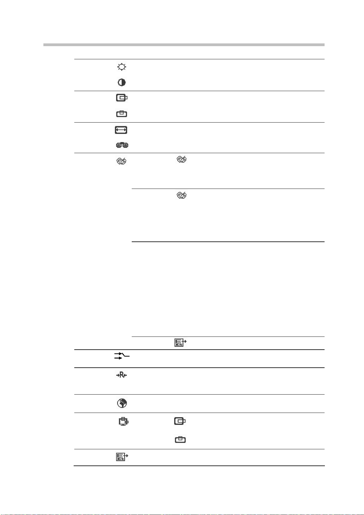
5.4.1 DVI-D signal connector pin assignment
The PIN assignment of the DVI-D connector / cable is as following:
PIN Signal PIN Signal PIN Signal
TMDS Data 2-
1
TMDS Data 2+
2 10 TMDS Data 1+ 18 TMDS Data 0+
TMDS Data 2/4 shield
3
TMDS Data 4- (open)
4
TMDS Data 4+ (open)
5
DDC Clock
6
DDC Data
7
Analog Vertical Sync
8
9 TMDS Data 1- 17 TMDS Data 0-
TMDS Data 1/3 shield
11
12 TMDS Data 3- (open) 20 TMDS Data 5- (open)
13 TMDS Data 3+ (open) 21
+5V Power
14
15 GND 23 Clock+
16 Hot Plug Detect 24 Clock-
19 TMDS Data 0/5 shield
TMDS Data 5+ (open)
22 Clock shield
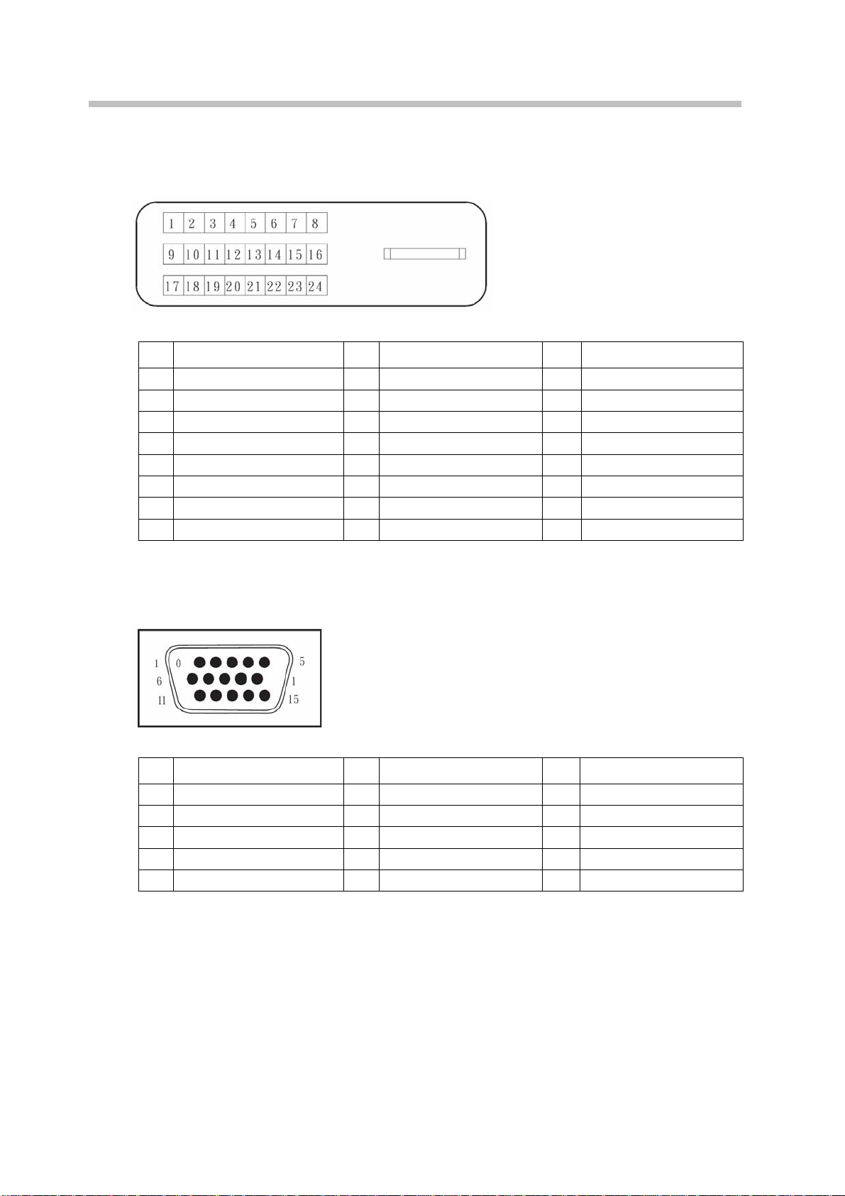
5.4.2 D-Sub signal connector pin assignment
The PIN assignment of the mini D-SUB connector / cable is as following:
PIN Signal PIN Signal PIN Signal
1 Red 6 Ground Red 11 Ground (open)
2 Green 7 Ground Green 12 SDA (DDC Data)
3 Blue 8 Ground Blue 13 H – Sync
4 Ground (open) 9 +5 V for DDC 14 V – Sync
5 No Pin (ground) 10 Ground 15 SCL (DDC Clock)
13
Page 15

Appendix A Trouble shooting
Before calling for service, please check the information in this section to see if you can
remedy any problems by yourself. If you need assistance, please call the dealer where you
purchased the LCD monitor.
1) There is no SCREEN image
Please check these items:
(1) The power cord is securely connected to the monitor, the adaptor, and the wall
outlet.
(2) Check the signal cable connection between the monitor and the computer.
(3) Adjust the brightness and contrast controls.
(4) Monitor in power saving mode.
2) Display image is too large or small
(1) Use the OSD controls to adjust Auto Setup.
3) The colors are discord
(1) Signal cable properly connected?
(2) Use OSD controls to adjust the color control setting.
4) The image is too light or too dark
(1) Use OSD controls to adjust the brightness and contrast.
5) There is no sound or sound is low
(1) Check the audio cable connector.
(2) Make sure the computer sound program is working.
(3) Change the volume setting. Adjust your sound card or computer volume setting.
14
 Loading...