

BenQ T201WA Service Manual

l
y
Product Service Manual – Level 2 Product Service Manual – Level 2
Service Manual for BenQ: Service Manual for BenQ:
T201WA T201WA
P/N: 9J.07N72.39x P/N: 9J.07N72.39x
Applicable for All Regions Applicable for All Regions
Version: 002 Version: 002
Date:2007/5/17 Date:2007/5/17
Notice: Notice:
- For RO to input specific “Legal Requirement” in specific NS regarding to responsibility and liabilit- For RO to input specific “Legal Requirement” in specific NS regarding to responsibility and liabilit
statements.
- Please check BenQ’s eSupport web site,
recent version of this manual.
http://esupport.benq.com, to ensure that you have the most
First Edition (June, 2006)
© Copyright BenQ Corporation 2006. All Right Reserv ed.
- 1 -

Content Index
Abbreviations & Acronyms......................................................................................................................3
1. About This Manual...............................................................................................................................3
1.1. Trademark..........................................................................................................................3
2. Introduction..........................................................................................................................................4
2.1. RoHS (2002/95/EC) Requirements – Applied to all countries require RoHS. .................4
2.2. Safety Notice.....................................................................................................................4
2.3. General Descriptions.........................................................................................................4
2.4. Related Service Information..............................................................................................4
3. Product Overview...............................................................................................................................5
3.1. Specification......................................................................................................................5
3.2. Customer Acceptance.......................................................................................................19
4. Disassembly /Assembly.......................................................................................................................25
4.1. Exploded View .................................................................................................................25
4.2. Disassembly /Assembly ....................................................................................................26
5. Level 1 Cosmetic / Appearance / Alignment Service...........................................................................28
5.1 Software / Firmware Upgrade Process ..............................................................................28
5.2. Alignment procedure (for function adjustment).............................................................36
6. Level 2 Circuit Board and Standard Parts Replacement .....................................................................42
6.1. Block diagram..................................................................................................................42
6.2. TROUBLE SHOOTING GUIDE .....................................................................................53
6.3. Spare Parts List.................................................................................................................56
Appendix 1 – Screw List / Torque.......................................................................................................................................... 57
Appendix 2 Physical Dimension Front View and Side view .................................................................................................. 57
- 2 -

Abbreviations & Acronyms
About This Manual
1.
This manual contains information about maintenance and service of BenQ products. Use this
manual to perform diagnostics tests, troubleshoot problems, and align the BenQ product.
1.1. Trademark
The following terms are trademarks of BenQ Corporation:
BenQ
Importance
Only trained service personnel who are familiar with this BenQ Product shall
perform service or maintenance to it. Before performing any maintenance or service,
the engineer MUST read the “Safety Note”.
- 3 -

2. Introduction
This section contains general service information, please read through carefully. It
should be stored for easy access place for quick reference.
2.1. RoHS (2002/95/EC) Requirements – Applied to all countries require RoHS.
The RoHS (Restriction of Hazardous Substance in Electrical and Electronic Equipment Directive)
is a legal requirement by EU (European Union) for the global electronics industry which sold in
EU and some counties also require this requirement. Any electrical and electronics products
launched in the market after June 2006 should meet this RoHS requirements. Products launched in
the market before June 2006 are not required to compliant with RoHS parts. If the original parts
are not RoHS complaints, the replacement parts can be non ROHS complaints, but if the original
parts are RoHS compliant, the replacement parts MUST be RoHS complaints.
If the product service or maintenance require replacing any parts, please confirming the RoHS
requirement before replace them.
2.2. Safety Notice
1. Make sure your working environment is dry and clean, and meets all government safety
requirements.
2. Ensure that other persons are safe while you are servicing the product.
3. DO NOT perform any action that may cause a hazard to the customer or make the product
unsafe.
4. Use proper safety devices to ensure your personal safety.
5. Always use approved tools and test equipment for servicing.
6. Never assume the product’s power is disconnected from the mains power supply. Check that it
is disconnected before opening the product’s cabinet.
7. Modules containing electrical components are sensitive to electrostatic discharge (ESD).
Follow ESD safety procedures while handling these parts.
8. Some products contain more than one battery. Do not disassemble any battery, or expose it to
high temperatures such as throwing into fire, or it may explode.
9.
Refer to government requirements for battery recycling or disposal.
10.
2.3. General Descriptions
This Service Manual contains general information. There are 3 levels of service:
Level 1: Cosmetic / Appearance / Alignment Service
Level 2: Circuit Board or Standard Parts Replacement
Level 3: Component Repair to Circuit Boards
2.4. Related Service Information
BenQ Global Service Website: http://support.benq.com/front/benqmain.asp
eSupport Website:
- 4 -
http://bqpgsr.benq.corp.com/customize/asplogin.asp
3. Product Overview
N
N
N
N
N
3.1. Specification
T201W is defined as an entry-level 20 inch wide monitor targeting on both commercial and consumer users
that need an affordable 20” wide monitor. The monitor supports maximum resolution up to 1680x1080 with
analog, digital inputs.
The features summary is shown as below,
*All panel spec. in C201 definition depends on the variance of panel source.
*All spec. of monitor need to warm up at least 1hr.
*All spec. of monitor need to set “Color” on “User preset” mode.
*All spec. of monitor mentioned “Contrast Ratio” the test co ndition: Set “brightness” at 100, and “contrast” at
80.
*All spec. of monitor mentioned “Luminance” the test condition: Set “brightness” at 100, and “contrast” at 100.
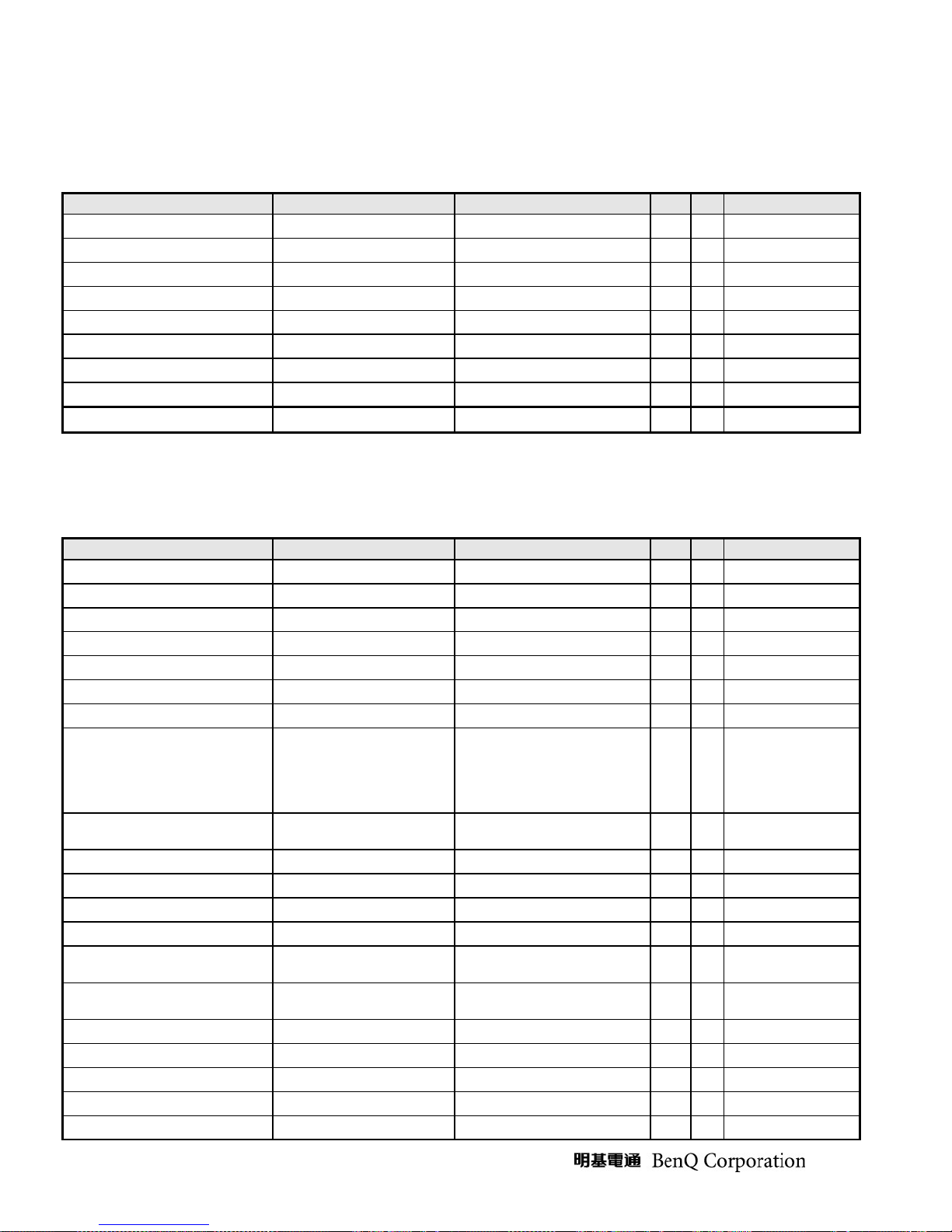
Feature items Specifications Remark
Panel supplier & module name AUO M201SP01 V0 TN
Screen diagonal 20.1” 433.44(H) x 270.90(V)
Display Format 1680 (H) x 1050 (V) Panel Display information
Pixel Pitch 0.258 mm x 0.258 mm per one triad
Viewing Angle (@ Contrast Ratio >= 10)
Analog interface with Scaling supported Yes With 15-pin D-sub connector
DVI interface with Scaling supported Yes With 24-pin DVI-D connector
Video interface with Scaling supported No
Max resolution mode supported 1680 (H) x 1050 (V)@60Hz
umber of Display Colors supported 16.2 millions RGB 6 bits + FRC data
Contrast Ratio 1000:1 (typ.),750:1(min)
Luminance 250 cd/m2 (typ.),200 cd/m2 (min)
AC power input Yes 90-264 Volts, 47-63 Hz.
DC power input (with AC power adapter) No
DPMS supported Yes <1W
LED indicator for power status showed Yes Green/Amber/Non
OSD for control & information supported Yes
Multi-language supported for OSD Yes 8 languages
Buttons control supported Yes
Flywheel control supported
Scaling function supported Yes
Auto adjustment function supported Yes “I-Key” function
DDC function supported (EDID ver. 1. 3) Yes DDC2B
DDC-CI support version 1.1 or later Yes DDC-CI
Audio speakers supported Yes
Audio Jack (input connector) supported Yes
Earphone Jack (input connector) supported Yes
Microphone function supported
Mechanical Tilt base design Yes From -2 to +22 degree
VESA wall mounting design Yes
Mechanical Rotate design
Mechanical Lift base design
R+L:160 degrees (typ)
and U+D: 160 degrees (typ)
R/L:140 degrees (min)
and U/D: 140 degrees (min)
6 buttons including 1 monitor
power on/off control butt on .
o
o
o
o
- 5 -
Kensington compatible lock design Yes
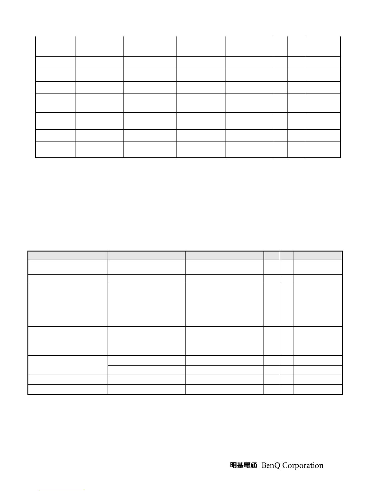
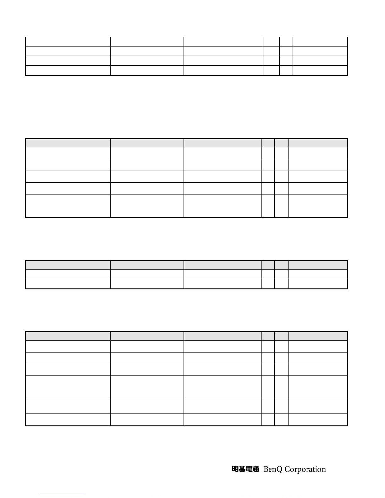
3.1.2. Operational Specification
3.1.2.1 Power supply
Item Condition Spec OK N.A Remark
Input Voltage range
Input Current range
Power Consumption
DPMS
Inrush Current
Earth Leakage Current
Hi-Pot
Power Line Transient
CCFL operation range
Universal input full range 90~264VAC /47~63Hz
90 ~ 264VAC < 2.0 Arms
Normal “On” operation < =49 W
DPMS “Off” state < 1 W
110 VAC
220 VAC
264 VAC/50Hz < 3.5 mA
1. 1500VAC, 1 sec
2. Ground test: 30A, 1sec
IEC1000-4-4 1KV
IEC1000-4-5 (Surge)
90 ~ 264VAC 4~8mA
< 30 A (peak)
< 60 A (peak)
Without damage
< 0.1 ohm
Common: 2KV,
Differential: 1KV
√
√
√
√
√
√
√
√
√
√
LED: Green
LED: Amber
Cold-start
(on-line test)
(in-lab test)
Depends on panel
source
CCFL Frequency
Power cord
90 ~ 264VAC 40KHz ~ 60KHz
Color: Black
Length: 1500
+/- 50 mm
√
√
Depends on panel
source
3.1.2.2 Signal interface
Item Condition Spec OK N.A Remark
√
√
√
√
√
√
√
√
√
√
√
For 15-pin D-sub
For 24-pin DVI-D
For 15-pin D-sub
Video input
For 15-pin D-sub
Refer to VESA VSIS
Standard V1R1
10KΩ for application
Signal Cable
Pin assignment
Sync input
15-pin D-Sub
24-pin DVI-D
15-pin D-sub connector
24-pin DVI-D connector
Signal type
Level
Impedance
Signal type
Level
Impedance
Sync Pulse Width (SPW)
Color: Black
Length: 1500
Color: Black
Length: 2000
Separate analog R/G/B
700 mV (peak to peak)
75 Ohms +/- 1.5 Ohms
Separate H/V-sync
Composite H/V-sync
(Positive/Negative)
Logic High: 2.4V ~ 5.5V
Logic Low: 0V ~ 0.5V
Minimum 2.2K
0.7μs < H-SPW
1H < V-SPW
+/-
30 mm
+/-
50 mm
See Note-1
See Note-2
(TTL level)
Ω(pull down)
- 6 -
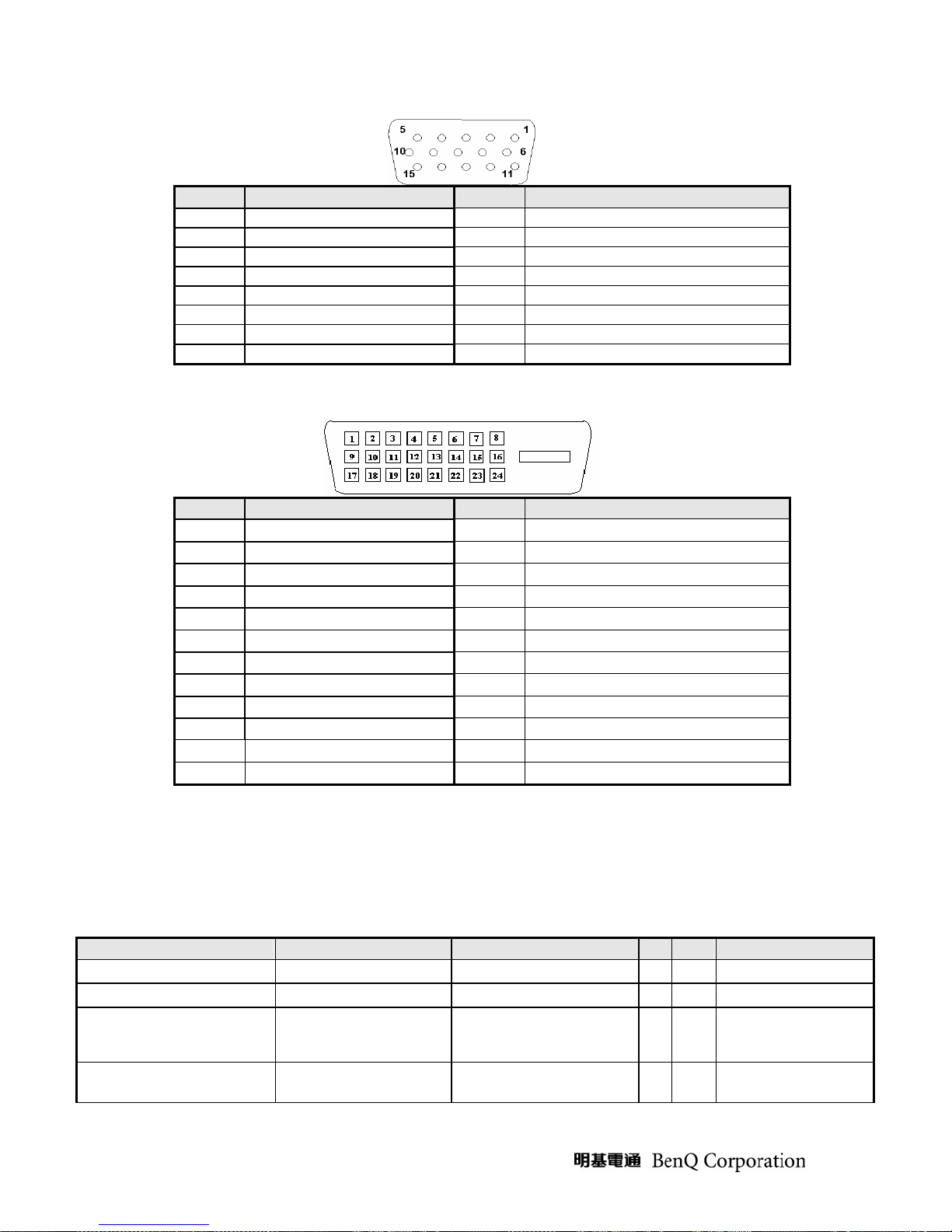
Note-1: The pin assignment of 15-pin D-sub connector is as below,
Pin Signal Assignment Pin Signal Assignment
1 Red video 9 PC5V (+5 volt power)
2 Green video 10 Sync Ground
3 Blue video 11 Ground
4 Ground 12 SDA
5 Cable Detected 13 H-Sync (or H+V)
6 Red Ground 14 V-sync
7 Green Ground 15 SCL
8 Blue Ground
Note-2: The pin assignment of 24-pin DVI-D connector is as below,
Pin Signal Assignment Pin Signal Assignment
1
2
3
4
5
6
7
8
9
10
11
12
TMDS RX2TMDS RX2+
TMDS Ground
Floating
Floating
DDC Clock
DDC Data
Floating
TMDS RX1TMDS RX1+
TMDS Ground
Floating
13
Floating
14
+5V Power
15
Ground
16
Hot Plug Detect
17
TMDS RX0-
18
TMDS RX0+
19
TMDS Ground
20
Floating
21
Floating
22
TMDS Ground
23
TMDS Clock+
24
TMDS Clock-
3.1.2.3 Video performance
Item Condition Spec OK N.A Remark
Max. support Pixel rate
Max. Resolution
Rise time + Fall time
Settling Time after
overshoot /undershoot
- 7 -
< 3.1 ns
165 MHz
1680 x 1050
(50% of minimum pixel
clock period)
< 5% final full-scale value
√
√
√
√
1680 x 1050 @ 60Hz
(max. support timing)
Refer to VESA VSIS
Standard V1R1
Overshoot/Undershoot
< 12% of step function
voltage level over the full
voltage range
√
Refer to VESA VSIS
Standard V1R1
f
3.1.2.4 Scan range
Item Condition Spec OK N.A Remark
Horizontal
Vertical
30-82 KHz
56-76 Hz
√
√
3.1.2.5 Plug & Play DDC2B DDC-CISupport
Item Condition Spec OK N.A Remark
DDC channel type
EDID
DDC-CI
DDC2B
Version 1.3
Version 1.1 or Later
√
√
√
Refer to FP92E S/W
spec. document to see
the detailed EDID data
definition.
Refer to FP202 S/W
spec
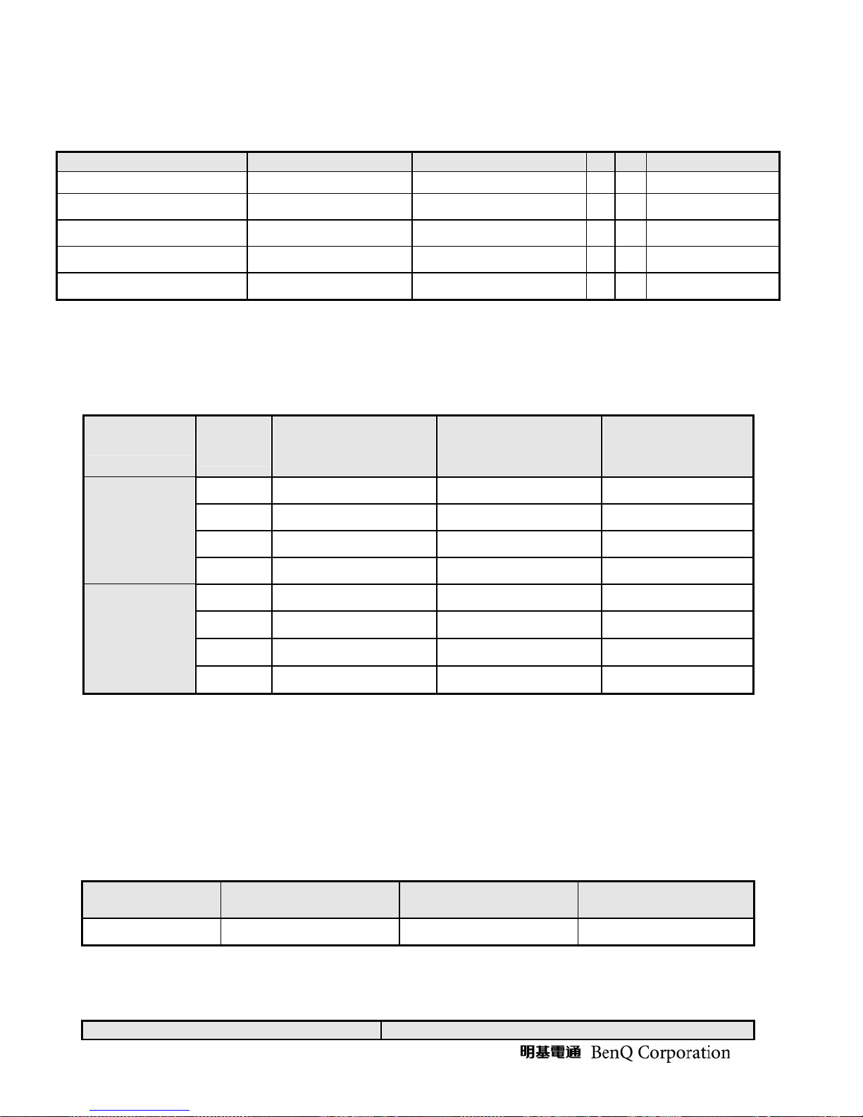
3.1.2.6 Support Timings
Input Timing
Resolution
40 x 480
40 x 480
20 x 400
00 x 600
00 x 600
32 x 624
024 x 768
024 x 768
152 x 720
Horizontal Vertical Dot Clock Actual display
31.47(N) 60.00(N) 25.175 1680x1050
37.50(N) 75.00(N) 31.50 1680x1050
31.47(N) 70.08(P) 28.321 1680x1050
37.88(P) 60.32(P) 40.00 1680x1050
46.88(P) 75.00(P) 49.50
49.72 74.55 57.283
48.36(N) 60.00(N) 65.00
60.02(N) 75.03(N) 78.75
44.86(N) 60.00(P) 66.75
Actual Output
1680x1050
1680x1050
1680x1050
1680x1050
1680x1050
OK N.A
√
√
√
√
√
√
√
√
Remark
VGA
VGA
VGA
VESA
VESA
MAC
VESA
VESA
VT 0.83MA
DVT 16:10
152 x 870
152 x 900
- 8 -
68.68 75.06 100.00
61.80 65.96 92.978
1680x1050
1680x1050
√
√
MAC
SUN
280 x 768
47.396(P) 60.0(N) 68.25
1680x1050
√
CVT
0.98M9-R
280 x 960
280 x 1024
280 x 1024
440 x 900
600 x 1000
600 x 1200
680 x 1050
60.00 60.00 108.00
63.98(P) 60.00(P) 108.00
79.98(P) 75.02(P) 135.00
55.94(N) 59.89(P) 106.50
61.648(P) 60.00(N) 108.50
75.00(P) 60.00(P) 162.00
65.29(N) 60.00(P) 146.25 1680x1050
Note-3: “P”, “N” stands for “Positive”, “Negative” polarity of incoming H-sync/V-sync (input timing).
3.1.3. Operational & Functional Specification
3.1.3.1 Video performance
1680x1050
1680x1050
1680x1050
1680x1050
1680x1050
1680x1050
√
√
√
√
√
√
√
VESA
VESA
VESA
CVT
1.30MA
CVT
1.60MA-R
VESA
CVT
1.76MA
*All spec. of monitor need to warm up at least 1hr.
Item Condition Spec OK N.A Remark
Resolution
Contrast ratio
Brightness
Response time
Viewing angle
CIE coordinate of White
Display colors
Any input resolution modes
which are under 1680x1050
1000:1 (typ.),700:1(min)
At R/G/B saturated condition 250 cd/m2 (typ.),200(min)
Rising + Falling time 5 ms (typ.),7ms(max)
At Contrast ratio = 10 R/L: 80/80 degrees (typ.)
At Contrast ratio = 10 U/D: 80/80 degrees (typ.)
16.2 Millions colors
(0.313, 0.329) ± (0.03, 0.03)
1680x1050
√
√
√
Test Equipment:
Westar TRD 100
√
√
√
√
6 bit + FRC
√
or equal level
equipment ;
3.1.3.2 Brightness Adjustable Range
- 9 -
Item Condition Spec OK N.A Remark
p
Brightness adjustable range
At default contrast level
(saturate point) & Full-white
color pattern
(Max. brightness value –
Min. brightness value)
≧ 100 cd/㎡
√
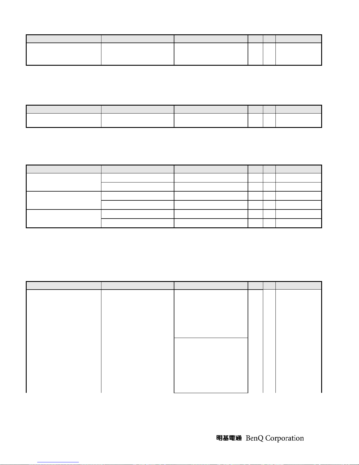
3.1.3.3 Acoustical Noise
Item Condition Spec OK N.A Remark
Acoustical Noise
At 1 meter distance
& “Audio” function disabled
≦ 30 dB/A
√
3.1.3.4 Environment
Item Condition Spec OK N.A Remark
Temperature
Humidity
Altitude
Operating
Non-operating
Operating 10 ~ 90%
Non-operating 10 ~ 90%
Operating 0~3048m (10,000ft)
Non-operating 0~12,192m (40,000ft)
0 ~ +40 ℃
-20 ~ +60 ℃
√
√
Non-condensing
√
Non-condensing
√
Without packing
√
With packing
√
3.1.3.5 Transportation
Item Condition Spec OK N.A Remark
√
(1) Vibration
(1) Sine wave
5~200Hz 1.5G, 1 octave/min,
15 min dwell on each resonant
Package, Non-Operating
frequency, all primary axis,
one sweep (30 min minimum)
er orientation, total of 90+
min.
(2) Random
5 ~100 Hz, 0 dB/Oct. 0.015
2
/Hz
g
100 ~200 Hz, -6 dB/Oct.
200 Hz, 0.0038 g
Equivalent to 1.47 Grms, All
primary axis, 20 min perorientation, total is 60 min.
2
/Hz
- 10 -
(2) Unpackaged Vibration
(3) Drop
(4) Shock
Unpackaged, Non-Operating
Package, Non-Operating
Wooden package, Non-
Operating
3.1.3.6 Electrostatic Discharge Requirements
(3) Procedure:
Confirmed sample with
appearance and function ready
before testing then compare
with after test record as
brightness, uniformity and
contrast ratio. Perform
random vibration after sinewave vibration test.
Test Spectrum:
20 Hz 0.0185(g2/Hz)
200Hz 0.0185(g2/Hz)
Duration : 5 Minutes
Axis : 3 axis ( Horizontal
and Vertical axis ,Z axis)
91 cm Height (MP stage)
(1 corner, 3 edges, 6 faces)
Waveform: half sine
Faces: 6 sides/ per orientation
3 shocks.
Duration: <3ms
Velocity accelerate: 75g
√
√
√
Item Condition Spec OK N.A Remark
Electrostatic Discharge
IEC801-2 standard
Contact: 12KV
Air: 15KV
√
3.1.3.7 EMC
Item Condition Spec OK N.A Remark
TCO03
EMI
Electric
Magnetic
FCC part 15J class B
EN55022 class B
Band 1 < 10 V/m
Band 2 < 1 V/m
Band 1 < 200nT
Band 2 < 25nT
After Mass production under
1dBuv for constant measure.
Besides DNSF and VCCI
class-2 are optional.
√
√
√
3.1.3.8 Reliability
Item Condition Spec OK N.A Remark
MTBF Prediction
CCFL Life time
Refer to MIL-217F > 50,000 Hours
At 25±2℃, under 6.0mA
40,000 Hours (min)
√
√
Excluding CCFL
See Note-4
Note-4: CCFL lifetime is determined as the time at which brightness of lamp is 50%. The typical lifetime
of CCFL is on the condition at 6.0mA lamp current.
- 11 -

3.1.3.9 Audio performance
Item Condition Spec OK N.A Remark
Preamp + Power amp
(1)Output power
(2)THD (@ 1W)
(3)S/N ratio
Speaker Driver
(1)Nominal impedance
(2)Rated input power
(3)Frequency response
(4)Output sound pressure level
(5)Dimension of box
Audio Control
(1)Volume range
(2)Mute
@ 1KHz
@ 1W 1KHz
@ 1KHz
SPL-10dB
1W 0.5M
1 Wrms/CH
8 ± 15% ohm
1 W/CH
500~20KHz
35x16mm
0 ~100 levels
<1%
>40dB
80 ± 3 dB
2
On/Off
√
√
√
√
√
√
√
√
√
√
- 12 -
3.1.4. LCD Characteristics
3.1.4.1 The Physical definition & Technology summary of LCD panel
Item Condition Spec OK N.A Remark
LCD Panel Supplier
Panel type of Supplier
Screen Diagonal
Display area
Physical Size
Weight
Technology
Pixel pitch
Pixel arrangement
Display mode
Support color
AUO M201SP01 V0
511.13mm(20”)
Unit=mm 433.44(H) x 270.90(V)
Unit=mm 459.4(H) x296.4(V) x 18.3(D)
Unit=gram 2100(typ.)
TN type
Unit=mm 0.258(H) x 0.258(W)
R/G/B vertical stripe
16.2 Millions colors
AUO
Normally White
√
√
√
√
√
√
√
√
√
√
√
Per one triad
6 bit + FRC
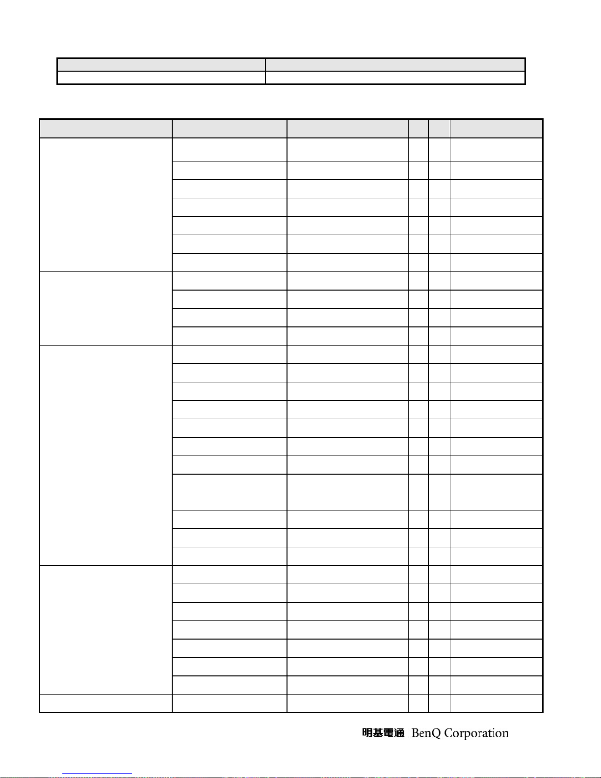
3.1.4.2 Optical characteristics of LCD panel
Item Unit Conditions Min. Typ. Max. Remark
Viewing Angle
Contrast ratio
Color / Chromaticity
Coordinates (CIE)
Color Coordinates (CIE) White
Luminance Uniformity
White Luminance @ CCFL
6.0mA (center)
Crosstalk (in 75Hz)
[degree]
[degree]
[degree]
[degree]
Normal Direction
[msec] Rising Time - 3.6 5.7
[msec] Falling Time - 1.4 2.3 Response Time
[msec] Rising + Falling - 5 8
[%] 9 points measurement
[cd/m2]
[%]
Horizontal (Right)
CR = 10 (Left)
Vertical (Up)
CR = 10 (Down)
Red x 0.61 0.64 0.67
Red y 0.31 0.32 0.37
Green x 0.26 0.29 0.32
Green y 0.58 0.61 0.64
Blue x 0.11 0.14 0.17
Blue y 0.04 0.07 0.10
White x 0.28 0.31 0.34
White y 0.30 0.33 0.36
70
70
70
70
700 1000
75 80
200 250 -
1.5
80
80
80
80
-
-
-
-
* The test methods for the above items’ definition, please refer to the relative panel specification.
- 13 -
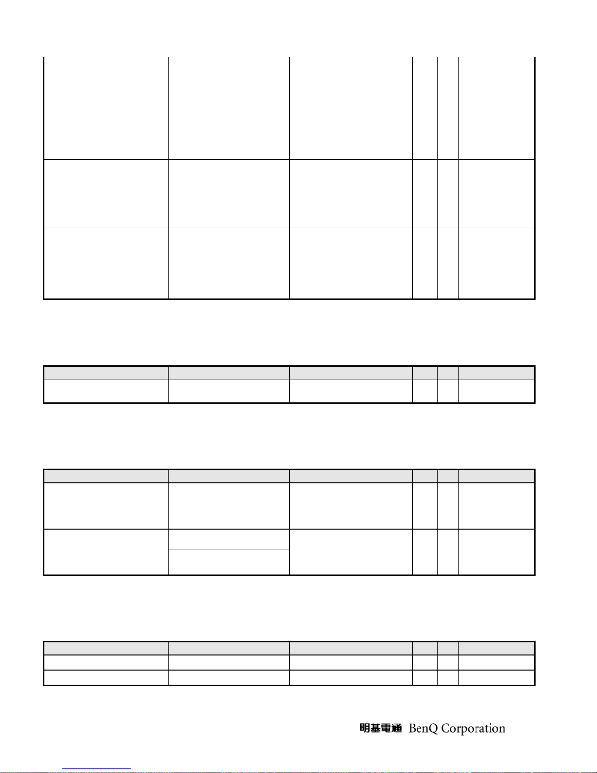
3.1.5. User Controls
3.1.5.1 User’s hardware control definition
Item Condition Spec OK N.A Remark
Power button
Enter button
Up/Inc. button
Down/Dec. button
Exit button
Mode button
Input Select button
iKey button
Mute button
√
√
√
√
√
√
√
√
√
3.1.5.2 OSD control function definition
Item Condition Spec OK N.A Remark
Auto Adjust
Brightness
Contrast
Horizontal Position
Vertical Position
Pixel Clock
Phase
Color
OSD Position
OSD Time
OSD Lock
Language
Recall
Mode
Input Select
Sharpness
Display Information
Volume
Mute
Hot key for Brightness
Auto-Geometry
9300K
7500K
6500K
: Separate R/G/B adjustment
User
OSD Horizontal position
OSD Vertical position
From 5 sec to 30 sec
8 languages
Recall All
Standard / Movie / Dynamic /
Photo
D-sub
DVI
For input timing
√
√
√
√
√
√
√
√
√
√
√
√
√
√ √
√
√
√
√
√
√
- 14 -
Hot key for Contrast
Hot key for Volume
Hot key for Input Select
Hot key for Mode
* The detailed firmware functions’ specification, please refer to C212 S/W spec. document.
√
√
√
√
3.1.6. Mechanical Characteristics
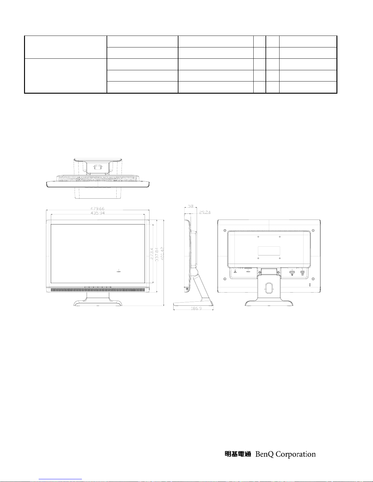
3.1.6.1 Dimension
Item Condition Spec OK N.A Remark
Bezel opening
Monitor without Stand
Monitor with Stand
Carton Box (outside)
Tilt and Swivel range
W x H x D mm
W x H x D mm
L x W x H mm
435.94*273.4 mm
479.66*337.84*58mm
479.66*400.42*186.9mm
567*493*131
Tilt: -2 ~ +22 degree
Swivel: 0 degree
√
√
√
√
√
3.1.6.2 Weight
Item Condition Spec OK N.A Remark
Monitor (Net)
Monitor with packing
(Gross)
4.34Kg
6.15 Kg
√
√
3.1.6.3 Plastic
Item Condition Spec OK N.A Remark
Flammability
Heat deflection To
UV stability
Resin
Texture
Color
ABS
ABS
>ABS<,94-HB
65 ℃
Delta E < 8.0
MPRII:
SD0150/GP35/D350/PA757)
MT-11010
Y7054A
ABS
√
√
√
√
√
√
RC partial texture
MT-11020
- 15 -
3.1.6.4 Carton
Item Condition Spec OK N.A Remark
Color
Material
Compression strength
Burst Strength
Stacked quantity
A Flute
416 KGF
16 KGF/cm
16 Layers
Kraft
2
√
√
√
√
√
3.1.7. Pallet & Shipment
3.1.7.1 Container Specification
Quantity of products
Stowing Type
With pallet
Without pallet
iner
20'
40'
20'
40'
(sets)
(Every container)
736 Pallet A: 64 Pallet A: 10
Pallet B: 48 Pallet B: 2
1536 Pallet A: 64 Pallet A: 24
Pallet B: Pallet B:
X X
X X
X X
X X
3.1.7.2 Carton Specification
3.1..7.2.1Product:
Quantity of Products
(sets)
(Every Pallet)
Quantity of pallet
(sets)
(Every Container)
Net Weight (Kg) Gross Weight (Kg)
4.34Kg 6.15 Kg 479.66*337.84*58mm 479.66*400.42*186.9mm
3.1..7.2.2Package:
Carton Interior Dimension (mm) Carton External Dimension (mm)
- 16 -
Dimension w/o Base
W*H*D (mm)
Dimension w/ Base
W*H*D (mm)
L*W*H L*W*H
555*478*111 567*493*131
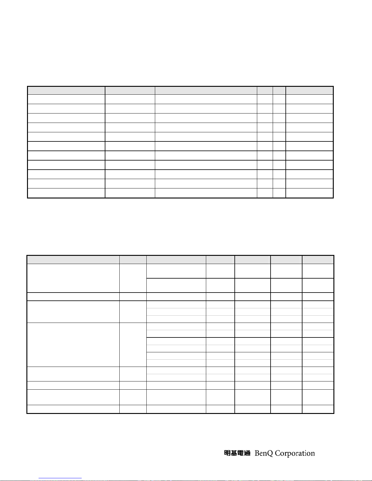
3.1.8. Certification
Item Condition Spec OK N.A Remark
Green design
API Doc. 715-C49
√
ISO14000
Requirement
Environment
PC-Monitor
Safety
Blue Angel German Standard
E-2000 Switzerland
EPA USA Standard
TCO’99
TCO’03
Green Mark
Microsoft Windows PC98/99
DPMS VESA
DDC 2B Version 1.3
USB External
UL (USA) UL60950 3rd edition
CSA (Canada) CAN/CSA-C22.2 No. 60950
Nordic / D.N.S.F EN60950
FIMKO EN60950
CE Mark 73/23/EEC
CB IEC60950
CB
EN60950
√
√
√
√
√
√
√
√
√
√
√
√
√
√
√
√
√
TUV/GS
CCC (China) CB4943
GOST EN60950
SASO IEC60950
CE Mark 89/336/EEC
FCC (USA) FCC Part 15 B
EN55022 Class B
EMC
X- Ray Requirement
- 17 -
CISPR 22 Class B
VCCI (Japan) VCCI Class B
BSMI (Taiwan) CNS 13438
C-Tick (Australia) AS/ NZS CISPR22
DHHS (21 CFR) USA X- Ray Standard
EN60950 /
EK1-ITB 2000:2003
√
√
√
√
√
√
√
√
√
√
√
√
DNHW
√
PTB German X- Ray standard
TUV / Ergo
Ergonomics
ISO 13406-2
prEN50279
Appendix: Physical Dimension Front View and Side view
Fig. 1 Physical Dimension Front View and Side view
√
√
√
√
- 18 -
 Loading...