

BenQ SX930 Service manual
Applicable Country & Regions:
All Regions
Notice:
Product Service Manual – Level 2
Service Manual for BenQ:
Projector/SX930
<9H.JEG77.15X>
Version: 00a
Date:2015/09/22
For RO to input specific “Legal Requirement” in specific NS regarding to responsibility and liability
statements.
Please check BenQ’s eSupport web site, http://esupport.benq.com, to ensure that you have
the most recent version of this manual.
First Edition (Sep., 2015)
© Copyright BenQ Corporation 2015 All Right Reserved.
1

Content Index
1. Abbreviations & Acronyms ............................................................. 4
2. About This Manual ............................................................................ 5
2.1 Trademark .................................................................................................................... 5
2.2 Introduction ................................................................................................................. 5
2.3 Important Service Information ..................................................................................... 5
2.4 Safety Notice ............................................................................................................... 6
2.5 Compliance Statement ................................................................................................. 6
2.6 General Descriptions ................................................................................................... 6
2.7 Related Service Information ......................................................................................... 6
3. Product Overview ............................................................................ 7
3.1 Specification Overview ................................................................................................ 8
3.2 Packing ....................................................................................................................... 28
3.3 Customer Acceptance................................................................................................ 35
4. Level 1 Cosmetic / Appearance / Alignment Service .............. 38
4.1 Cosmetic / Appearance Inspection Criteria................................................................ 38
4.2 OPERATIONAL INSPECTION CRITERIA ................................................................. 41
4.3 Software/Firmware Upgrade Process ......................................................................... 47
4.4 Factory Menu ............................................................................................................. 71
4.5 RS-232 connection ..................................................................................................... 76
4.6 Adjustment / Alignment Procedure............................................................................. 80
5. Level 2 Circuit Board and Standard Parts Replacement ....... 84
5.1 Product Exploded View .............................................................................................. 84
Module 2 – ASSY UPPER CASE ....................................................................................... 86
5.2 Product Disassembly / Assembly ................................................................................ 88
5.3 Module Assembly Key Point - Optical Engine ........................................................... 103
5.4 Module Assembly Key Point - Mechanical ................................................................. 117
5.5 Block Diagram ......................................................................................................... 133
5.6 Trouble shooting ...................................................................................................... 134
Appendix 2 - Code List: IR / RS232 / DDC Data ........................ 147
Appendix 3 – Ceiling Mount Drawing .......................................... 156
Appendix 4 - Optical Measurement ............................................. 157
Appendix 6 - Design Verification Test Procedure ...................... 168
Appendix 7 - Thermal and Noise Test Procedure ...................... 171
2

Update History
Revision
Chapter
Changes
Date
Rev. 00a
Initial version
2015/9/21
3
1. Abbreviations & Acronyms
Interface Between Data terminal Equipment and
Super Video Graphics Array, A screen resolution
Super XGA. A screen resolution of 1280x1024
Video Graphics Array. A screen resolution of
A
A/D Analog to Digital
B
BenQ BenQ Corporation
C
C/W Color Wheel
CM Concave Mirror
D
DLP Digital Light Processing / Texas Instruments®
DMD Digital Micro mirror Device
DVI Digital Video Interface
DVI-I Digital Video Interface-Integrated
P
PL Projection Lens
POM Pond of Mirrors
R
RS232
S
SVGA
SXGA
V
VGA
X
XGA A screen resolution of 1024x768 pixels.
Data Communications Equipment Employing
Serial Binary Data Interchange
of 800 x 600 pixels.
pixels.
640x480 pixels.
4

2. About This Manual
This manual contains information about maintenance and service of BenQ products. Use this manual
to perform diagnostics tests, troubleshoot problems, and align the BenQ product.
Important
Only trained service personnel who are familiar with this BenQ Product shall perform service
or maintenance to it. Before performing any maintenance or service, the engineer MUST
read the “Important Safety Information”
2.1 Trademark
The following terms are trademarks of BenQ Corporation:
BenQ
Other companies, products, or service names may be the trademarks of their respective companies.
2.2 Introduction
This section contains general service information, please read through carefully. It should be stored
for easy access place.
2.3 Important Service Information
RoHS (2002/95/EC) Requirements – Applied to all countries require RoHS.
The RoHS (Restriction of Hazardous Substance in Electrical and Electronic Equipment Directive) is a
legal requirement by EU (European Union) for the global electronics industry which sold in EU and
some counties also require this requirement. Any electrical and electronics products launched in
the market after June 2006 should meet this RoHS requirements. Products launched in the market
before June 2006 are not required to compliant with RoHS parts. If the original parts are not RoHS
complaints, the replacement parts can be non ROHS complaints, but if the original parts are RoHS
compliant, the replacement parts MUST be RoHS complaints.
If the product service or maintenance require replacing any parts, please confirming the RoHS
requirement before replace them.
5

2.4 Safety Notice
1 Make sure your working environment is dry and clean, and meets all government safety
requirements.
2 Ensure that other persons are safe while you are servicing the product.
3 DO NOT perform any action that may cause a hazard to the customer or make the product
unsafe.
4 Use proper safety devices to ensure your personal safety.
5 Always use approved tools and test equipment for servicing.
6 Never assume the product’s power is disconnected from the mains power supply. Check that it
is disconnected before opening the product’s cabinet.
7 Modules containing electrical components are sensitive to electrostatic discharge (ESD). Follow
ESD safety procedures while handling these parts.
8 Some products contain more than one battery. Do not disassemble any battery, or expose it to
high temperatures such as throwing into fire or it may explode.
9 Refer to government requirements for battery recycling or disposal.
2.5 Compliance Statement
Caution: This Optical Storage Product contains a Laser device. Refer to the product specifications
and your local Laser Safety Compliance Requirements.
2.6 General Descriptions
This Service Manual contains general information. There are 2 levels of service:
Level 1: Cosmetic / Appearance / Alignment Service
Level 2: Circuit Board or Standard Parts Replacement
2.7 Related Service Information
Service Web Site
eSupport Website:
BenQer: http://esupport.benq.com/v2
ASP: http://esupport.benq.com/
6

3. Product Overview
The projector consists of DLP projector controller, Lamp controller, Power supply system, and
System cooling controller. The DLP controller captures digital PC data and video data and then
converts them into the DMD display device. The Lamp controller dominates the lamp’s power and
synchronizes its frequency with color display sequence. The Power supply unit controls the AC line
power factor and converts primary voltage to secondary low voltages for digital board. The System
cooling controller drives the airflow to quench the lamp’s heat and electrical component’s heat.
Specification Overview
Panel Information
Projection Lens Specification
Optical Specification
Lamp Specification
Mechanical Specification
Packaging
Thermal Specification
Power Requirements
Compatibility
User Interface
Regulatory
Reliability
Other Feature
Input / Output Connectors
Input Terminals
Output Terminals
Control Terminals and Interface
Accessories
Environmental
Electrical Specification
Power Supply Specification
UI Specification
7
3.1 Specification Overview
SX930
Version: 02
Item
Specification
1.Panel / Driver IC Information
1.1 Panel Type
0.7"XGA 2xLVDS 14° Type DMD
1.2 Package Type
Type A
1.3 Size
0.7” 1.4 Pixels
1024(H) x 768(V)
1.5 Color Depth
30 Bits (
1.07 Billion Colors
) 1.6 Driver Type
DDP 4421
-HV
1.7 Panel Pixel Quality
Follow TI spec. (Refer to Appendix
4 ) 1.8 Image Imperfection
Follow TI spec. (Refer to Appendix
4 )
Display : NA
2. Projection Lens Geometry Specification
Wide
Tele 2.1 2.63
Wide:
Tele:
21.7 mm
34.64 mm
2.3 Zoom Ratio
1.6 ±2%
2.4 Throw Ratio
1.5~2.4 (Wide 78” ±3% @ 2.38m)
2.5 True Zoom
NA
2.6 H,V Offset*
2.6.1 Offset H(%)*
0% ± 2.5%
Appendix A.15)
2.6.2 Offset V(%)*
default 107.5% ± 2.5%
(Mode
B, Appendix A.15)
Vertical shift: +5%@ at default 107.5%±2.5%
2.7 Focus Range (m)
W: 1.86 ~ 9.32m T: 2.98 ~ 14.91 m
2.7.1 Screen Size (inch)
60” ~ 300” (Check by E pattern,
Appendix Pattern 6)
2.8 TV Distortion
Wide & Tele <1%
2.9 Keystone Distortion
Wide & Tele <1%
2.10 Screen Distortion*
|A,B| <=5mm, |C|<=5.0 mm @ 78" at 107.5% V offset
2.11 Focus Quality*
(1) The pattern can be uniformly focused
– then pass!
2.11.2
R G B
Defocus (Maximum) *
2.5 2.5 2.5 Flare (Maximum) *
3.5 3.5 3.5
Center Zone
All other area
R-G
<2/3
pixel
<1.0 pixel
9 B-G <2/3 pixel
Specification Overview
1.9 LAN Drive Type
Note: Projection Size for measurement as below: with mark ”*”
1. DMD Aspect ratio(16:9) ->projection size: 95 inch( diagonal) image size
2. DMD Aspect ratio(16:10) ->projection size: 87 inch( diagonal) image size
3. DMD Aspect ratio(4:3) >projection size: 78 inch diagonal) image size
2.1 F/#
2.2 Focal Length
2.6.3 Lens Shift(%)*
Control : A-top
"+": lens shift upward
"-": lens shift downward
2.11.1 区 Pattern*
2.12 Lateral Color*
(2) If it’s difficult to judge, then check 2.11.2
Defocus/Flare judge criteria refer to Appendix A16/17
8
<1.0 pixel
R-B
<1.0 pixel
<1.0 pixel
DOF 5 cm checked by E pattern. Refer to Appendix A24
"+" and"-" desinition
"+":move projector backward to far away the screen and until
backward distance(+) for the rear
":move projector forward to close to the screen and until
) for the front
2.14 Zoom Ring Torque
200~650g follow Qisda Lens spec
2.15
Focus Ring Torque
50~300g
follow Qisda Lens spec
2.16 Lens offset Position
115%
(SI Provide) *For Lens Shift Models.
2.17 Zoom&Focus shaking level
Follow limit sample (When needed)
2.18 Lens Shift Shaking(lock) Level
Lock level:5 Lens weight
2.19
Lens Shift Speed(sec)
3.Optical Specification
Normal: Minimum 6300 lm (
environment
>
35
, MKT>6000
97% of Optical
3.2 ANSI (
-
) uniformity
Minimum
-
50%
3.3 ISO Uniformity
Minimum 65%
3.4 ANSI Contrast
Minimum 150:1
3.5 FOFO Contrast
Minimum 1500:1 (WCE2), Refer to appendix
4-A23 3.6FOFO Contrast with DB
N.A.
3.7 color wheel segment
70Y30W90C30B65G75
3.8
color wheel speed
Data model:50Hz 2X 60Hz 2X
Color
x y Δ(u’,v’)
White
0.319
±
0.02
0.353
±
0.02
±0.03
Red 0.637±0.04
0.357±0.04
±0.04
Green
0.339±0.04
0.570±0.04
±0.04
Blue
0.147±0.03
0.068±0.03
±0.04
Color
△uv White
≦0.02
Red
≦0.03
Green
≦0.02
Blue
≦0.02
3.11 Color Gamut
Data model: Typical 60%
△≦
0.5 lux compared with center point @ full black
pattern
leakage is only described as the spot light with
obvious shape. The uniformity difference of black pattern is
2.13 DOF (Min. cm)
depth of focus.(後景深)
"focus limit. Record the backward distance(-
depth of focus.(後景深)
出貨
focus limit. Record the
(only for motorized len shift)
Test under “ * ” (diagonal) image size with Wide projection lens position.(base on lens best design value)
Reference Meter: CL-200 Meter (SN head:81531011, body:82521013)
N.A.
lm )
Normal: Typ 6650 lm (For reference)
3.1 ANSI Brightness
ECO: Typ 5320 lm (For reference)
Connect HDMI =Optical native(DMD-full-on)
If no HDMI Source, measure PC Input ≧
Native (DMD-full-on)
℃
3.9 Color Coordinate
(Confirm at PVT stage)
3.10 Color Uniformity
(Confirm at PVT stage)
(Compare to NTSC)
3.12 Light Leakage in AA
within 60”.
This light-
not included. (Except DMD Defect)
3.13 Light Leakage out of AA
1 lux, @ full black pattern with 60”~80“
3.14 Ghost
Ghost (Confirm at EVT2 stage)
3.15 Defect
(Color Band, Dark Corner,
3.16 Preset mode setting
4.Lamp Specification
4.1 Lamp
USHIO NSH465W E22.7
4.2 Lamp Sync Type
AC Lamp
4.3 Lamp Flick
Follow limited sample (When needed).
Normal Mode
440W
-> 425W
ECO
Mode
360W
Image
-
care or equivalent
NA
5. Mechanical Specification
5.1
Color & Texture
specifications
Refer to ID document for details
5.2 Physical
Dimensions
(Width X
5.3 Net Weight
≦8.5kg
5.4 Security Slot
Kensington compatible slot 20Kg break away force
5.5 Lens Cover
Detached lens cover
Adjustable foot in front, rubber foot in rear.
∘
Match BenQ’s c
eiling mount required.
All color of screws should similar with the plastic color which
5.9 During PVT stage, limited sample
5.10 Packaging
EPE 6. Thermal Specification
6.1 Surface held or touched for short
Normal surface:
Metal
Plastic
< 70
< 95
6.3 Exhaust Air
< 95
Normal mode: 39dBA @ 25°C(table center)
≦
≦3 lux, @ out of full black pattern with diagonal 80~120”
≦20 lux, @ out of full black pattern with diagonal >120”
(Except DMD Defect and high zoom ex: D zoom /zoom5 /
B zoom )
Dark band)
4.4 Lamp Power
Depth X Height)
5.6 Adjustment Feet
Follow limited sample (When needed).
446*336*152(mm)
Front/ Rear foot
Tilt: 0-4.5∘,
Right/Left: +4.0∘/-4.0
5.7 Ceiling Mounting
5.8 Screws
Use the same mounting as current shipping projectors.
close it.
of color and texture should be
approved by BenQ industrial
N/A
designer and mechanical
engineer.
Cushion Material
Mechanical component temperature at ambience 0~40℃
Metal< 60 ℃ Plastic< 85 ℃
periods
Bottom surface @25℃
Metal< 55 ℃ Plastic< 70 ℃
6.2 Surface which my be touched
℃
℃
℃
6.4 Audible Noise Level Typical
10
Eco mode: 36dBA @ 25°C(table center)
Max.
Normal mode
: 41dBA
@ 25°C(table center)
6.5 Fan Numbers
7 6.6 Sound Quality
6.7 Auto Blank distance
7.0 Power Requirements
7.1 Power Supply (Normal)
Max.
645W
0.5W Max. at 100 ~ 240VAC
3W MAX at 230VAC 50HZ for network
Normal
Typical 610W @110Vac
ECO
Typical 564W@110Vac
ECO Blank
Same as Eco Mode
7.3 Power Connector
IEC 60320 C14
7.4 Power
Switch
No
8.0 Compatibility
8.1 Data Compatibility
(Version 03)
8.1.1 RGB Digital
Refer to 2.1.4 HDMI/DVI Input
8.1.2 RGB Analog
Refer to 2.1.5 PC Input
8.1.3 Macintosh
MAC 13/16/19/21
8.2 Video Compatibility
8.2.1 SDTV
480i/576i
8.2.2 EDTV
480P/576P
8.2.3 HDTV
720@50P/60P,1080@50i/60i/24p/25p/30p/50p/60p
NTSC/ NTSC4.43/ PAL (Including PAL
-
M, PAL
-
N)/ SECAM/
8.3 Frequency
8.3.1 H
-
Sync
15~102KHz
8.3.2 V
-
Sync
23 ~ 120 Hz
8.4 DDC
EDID 1.3
9.0 User Interface
10 Keys ( Same as SU922 )
9.2 LED Indicators
3 LEDS
9.2.1 Power On/Off Status
Refer to 4.4 LED definition
9.2.2 Lamp Status
Refer to 4.4 LED definition
9.2.3 Temperature Status
Refer to 4.4 LED definition
Horizontal keystone and adjustable range
30
9.4 Remote Control
5F.261W9.211 (WW SKU)
/ 5F.261W9.151 (J SKU)
10.0 Regulatory
Vendor : Refer to RFQ
Vendor : Refer to RFQ
10.3 ESD
Follow IEC 61000
-4-
2 and EN55024 regulation
Eco mode : 38dBA @ 25°C(table center)
1K~20K < 9dB (follow ECMA-74)
NA
7.2 Power consumption
8.2.4 Video
Standby
PAL60/
(disable loop through, Lan function)
mode
9.1 Operator Keypad
9.3 Electric Keystone
10.1 Safety
10.2 EMC
Power ; Source ;Auto ; Blank ; Mode/Enter ; Menu/Exit ;
Right (Keystone ) ; Left (Keystone ) ; Up(Keystone+) ;
Down(Keystone-)
Vertical keystone and adjustable range 30
Internal : Refer to B106 document
Internal : Refer to B106 document
11
10.4 GP
1) BenQ
Restriction of Hazardous Substance Guideline
11.0 Reliability
40000 hours except DMD chip, Color wheel, Lamp and Fan,
1). Lamp hour =
Total lamp hour= X(hours used in Normal
11.2.1 Normal Mode
2000 hrs(Lamp only)
11.2.2 ECO Mode
2500 hrs(Lamp
only)
11.2.3 Smart Eco Mode (ImageCare)
NA
11.2.4 Smart Eco Mode (LampCare)
NA
11.2.5 Image life
NA
12.0 Other Feature
12.1 Color Temperature at Normal
12.2 Digital Zoom
NA
12.3 Aspect Ratio
Auto/Real/4:3/16:9/16:10
12.4 Projection Methods
Floor Front/Ceiling Front/Floor Rear/Ceiling Rear
12.5 3D Display
Yes, support DLP 3D
12.6 LAN
12.6.1 LAN
-
Crestron eControl
12.6.2 LAN
-
RoomView compatible
12.6.3 LAN
-
PJ Link compatible
YES 12.6.4 LAN
-
AMX compatible
YES 12.6.5 LAN
-
Display(1 to many)
12.6.6 LAN over RS23
12.7 Certificate
12.7.1 Win8 Certificate
YES 12.7.2 Crestron Certificate
NA
12.7.3 WEEE Certificate
NA
12.7.4 DTS Certificate
No
12.7.5 HDMI Certificate
NA
12.7.6 MHL Certificate
NA
12.8 WCE3.0
NA
Turn on Eco Blank:
When user presses the button once, the image would
toEco Blank mode and show "Blank" and other words in
The lamp power will dim to Lamp Dimmest Power (follow
(SUP-QM-07-02)
2) Other GP control items please refer PRR
11.1 MTBF
11.2 Lamp Lifetime
(Lumen Care)
(sRGB mode)
Ballast
mode) + Y(hours used in Eco mode)
X= lamp life spec of Eco/lamp life spec of Normal mode
Y= lamp life spec of Eco/lamp life spec of Eco mode
5500/6500/7500
YES
(4 to 1)
(Follow RS232 command)
12.9 Screen Saver Mode
(Eco Blank & Lamp Saver)
YES
No
YES
1.
turn
the bottom of screen.
2.
Lamp Capability).
Turn off Eco Blank:
12
1. When the image is in Eco Blank mode and user done:
(1) Press any Keypad
Turn on Lamp Saver:
When there is no signal input and didn’t do any projector
operation last to 3 mins, a full black pattern will be
The lamp power will dim to Eco Blank (follow Lamp
Turn off Lamp Saver:
12.10 Smart ECO*
NA
12.11 Off
-
line cooling
NA
13.0 Green Eco design
13.1BenQ ecoFACTS
Refer to BenQ ecoFACTS Checkinglist
(2) Press IR
The projector would turn off Eco Blank mode
The lamp power will back to original mode power
1.
displayed with “No signal” and other message
Capability).
1. When the image is in Lamp Saver mode and user done:
(1) Press any Keypad
(2) Input Signal
(3) Press IR
The projector would turn off Lamp Saver mode
The lamp power will back to original mode power
Note: Follow USHIO Lamp Operating.
13

Input / Output Connectors
1.Input Terminals
RGB DB
-
15 x 1 (shared with Component 1)
1.2 Computer Input
- 2 NA
1.3 Video
Composite Video (RCA X 1)
1.4 S
-
Video
S-
Video (Mini Din) X 1
1.5 Component
- 1 shared with computer 1
1.6 Component
- 2 NA 1.7 DVI
- 1 NA 1.8 DVI
- 2 NA 1.9 HDMI Digital Video
– 1 HDMI version: 1.4x1/ HDCP version: 1.4 / MHL2.1
1.9.1 Support Audio Input
YES 1.9.2 CEC control
No
1.9.3 HDMI Receive Distance
Auditorium model (Deep color 10bit:AWG26 30m )
1.10 HDMI Digital Video
– 2 HDMI version: 1.4x1 HDCP version: 1.4
1.10.1 Support Audio Input
YES 1.10.2 CEC control
No
1.11 Audio Input
– 1 (RCA R &L)
RCA Audio Jack right and left
1.11.1 Related Source
Video/S
-
Video audio input
1.12 Audio Input
– 2 (Mini Jack)
3.5mm S
tereo
Mini-Jack x 1
1.12.1 Related Source
Computer / Component audio input
1.12.2 Input Signal Level
500mVrms 10 K
1.13 Audio Input
– 3 (Mini Jack)
Microphone x1
1.14 Audio Input
– 4 (Mini Jack)
NA
1.15 USB Input
NA
1.16 LAN input
RJ45 LANx1 (Control only)
2.Output Terminals
2.1 Computer Output
RGB DB
-
15 x 1 (Female Type)
2.1.1 Signal Source
loop through Computer Input
-1
2.2 Audio Output
3.5mm Mono Mini
-
Jack x 1
Audio Input
-
1 / Audio Input
-
2/ Power on/off Ring Tone/HDMI
2.3 Speaker
10W X 2
2.3.1 Amplifier
10W per Channel @THD<=10%
3.Control Terminals
and Interface
3.1 IR Receiver
IR Receiver x2 (Front, Rear)
3.1.1 Angle
±30
3.1.2 Distance
0~8m
3.2 USB
3.2.1 Mini
-
USB B
3.2.1.1 FW Upgrade
Yes 3.2.1.2 Mouse Control
NA
3.2.1.3 USB Display
NA
3.2.1.4 output current
NA
3.2.2 USB A
3.2.2.1 Output current
Just only supply 5V @
1.5A
3.3 RS
-
232 D-Sub 9 Pins x 1, male Type
3.3.1 FW Upgrade
Yes
1.1 Computer Input - 1
2.2.1 Signal Source
audio/Microphone
14
3.3.2 Control Command
Yes 3.4 Lan Control
RJ-
45 x1. Follow IEEE802.3u
3.5 12V Trigger (Screen Control)
DC power jack(standby mode is off )
3.5.1 Driving Power
Output 12V,
500mA max
3.5.2 Overload Protection
< 1A
3.6 Wired Remote Control
No
1.Accessory
1. Power Cord 1.8m
X1
2. VGA Cable 1.8m
X1
3. CD x 1 (22 Language)
X 1 4. Quick
-
Start_Card (18Language)
X 1
5F.261W9.211 (WW SKU) / 5F.261W9.151 (J SKU)
6. Carry Case
N/A
7. Warranty Card
By SKU
8. Adapter
N/A
1.Environmental
Operating
0~40C, without condensation
Storage
-20~60°C, without condensation
Operating
10~90%RH, without condensation
Storage
10~90%RH, without condensation
Storage
30℃@0~12,200m above sea level
Signal
Parameter
Min Type Max
CVBS Luminance
Amplitude, total (video+ sync)
1
Volts peak to peak
Amplitude, video
0.7
Volts peak to peak
Amplitude, sync
0.3
Volts peak to peak
Impedance
75
ohm
Accessories
5. Remote Control
Environmental
1.1 Temperature
1.2 Humidity
1.3 Altitude
Electrical Specification
1.1 Electrical Interface Character
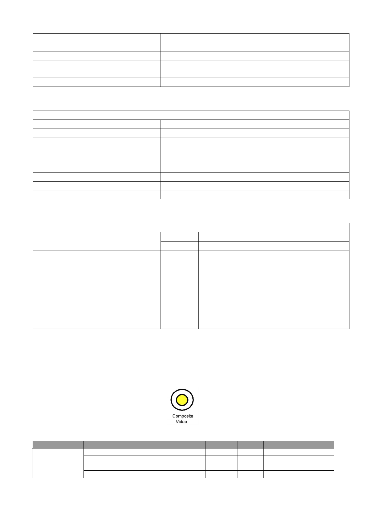
1.1.1 Composite Video Input
(1) Pin definition (RCA Jack)
(2) Signal Level:
Operating
Without high altitude mode 0°C~35°C @
0~1499m above sea level
With high altitude mode 0°C~30°C @
1500~3000m above sea level
15
(3) Support Timings: (Version 05)
Horizontal
Vertical
Sub-carrier
User Manual
3D Field
NTSC
15.73
60
3.58 Yes
◎
PAL 15.63
50
4.43 Yes
SECAM
15.63
50
4.25 or 4.41
Yes
PAL-M 15.73
60
3.58 Yes
PAL-N 15.63
50
3.58 Yes
PAL-60 15.73
60
4.43 Yes
NTSC4.43
15.73
60
4.43 Yes
PIN Signal
Parameter
Min Type Max 1
GND
2 GND
3 CVBS Luminance
Amplitude, total (video+ sync)
1
Volts peak to peak
Amplitude, video
0.7
Volts peak to peak
Amplitude, sync
0.3
Volts peak to peak
Impedance
75
ohm
Amplitude (for NTSC)
286
m Volts peak to peak
Amplitude (for PAL/SECAM)
300
m Volts peak to peak
Impedance
75
ohm
Horizontal
Vertical
Sub-carrier
User Manual
3D Field
NTSC
15.73
60
3.58 Yes
◎
PAL 15.63
50
4.43 Yes
SECAM
15.63
50
4.25 or 4.41
Yes
PAL-M 15.73
60
3.58 Yes
PAL-N 15.63
50
3.58 Yes
PAL-60 15.73
60
4.43 Yes
NTSC4.43
15.73
60
4.43 Yes
Video mode
frequency
(KHz)
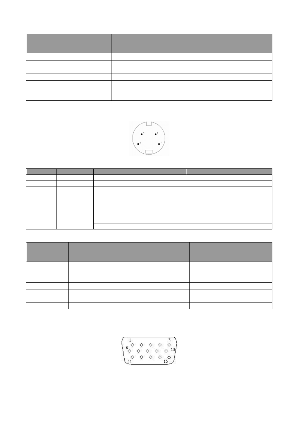
1.1.2 S-Video Input
(1) Pin definition (Mini Din)
4-pin Mini Din Connector
(2) Signal Level:
frequency
(Hz)
Frequency
(MHz)
Supported
Sequential
4 CVBS Luminance
(3) Support Timings: (Version 05)
Video mode
frequency
(KHz)
frequency
(Hz)
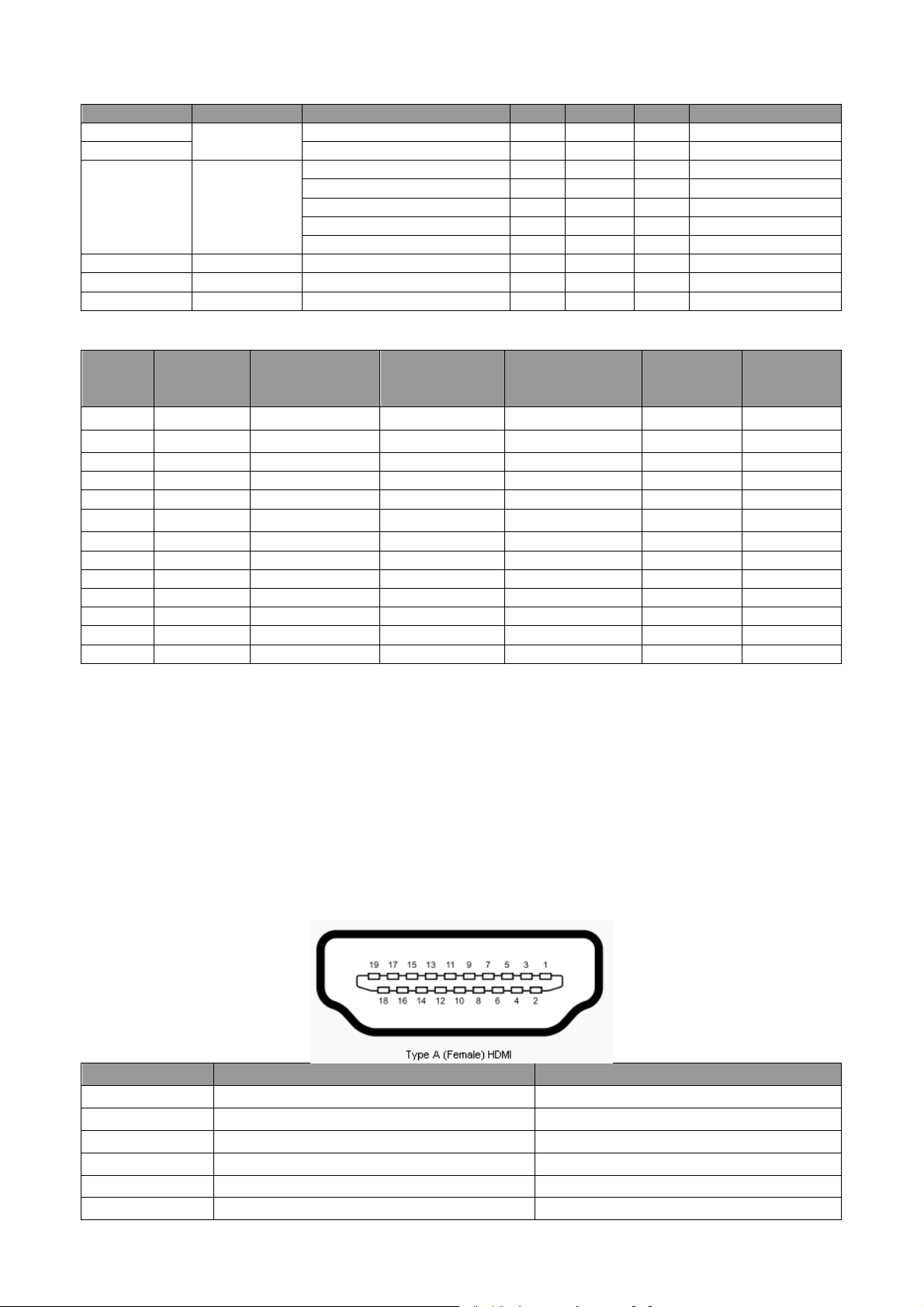
1.1.3 Component Video Input
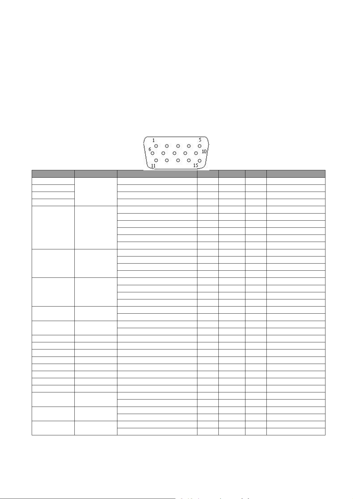
(1) Pin definition { RGB DB-15 x 1 (Female Type) }
Frequency
(MHz)
Supported
Sequential
16
(2) Signal Level:
Pin Signal
Parameter
Min Type Max 1
Pr DATA
Impedance
75
Ohm
3
Black pedestal
0
Volts
Y DATA_SOG
Impedance
75
Ohm
Amplitude
1
Volts peak
-to-
peak
Video amplitude
0.7
Volts peak
-to-
peak Sync amplitude
0.3
Volts peak
-to-
peak Black pedestal
0
Volts 6 Red GND
7 Green GND
8 Blue GND
User Manual
3D Field
480i 720 x 480
15.73
59.94
13.5
Yes
480p
720 x 480
31.47
59.94
27
Yes
576i 720 x 576
15.63
50
13.5 Yes
576p
720 x 576
31.25
50 27
Yes
720/50p
1280 x 720
37.5 50 74.25
Yes
720/60p
1280 x 720
45.00
60
74.25
Yes
1080/50i
1920 x 1080
28.13
50
74.25
Yes
1080/60i
1920 x 1080
33.75
60
74.25
Yes
1080/24P
1920 x 1080
27 24 74.25
Yes
1080/25P
1920 x 1080
28.13
25
74.25
Yes
1080/30P
1920 x 1080
33.75
30
74.25
Yes
1080/50P
1920 x 1080
56.25
50
148.5
Yes
1080/60P
1920 x 1080
67.5 60
148.5
Yes
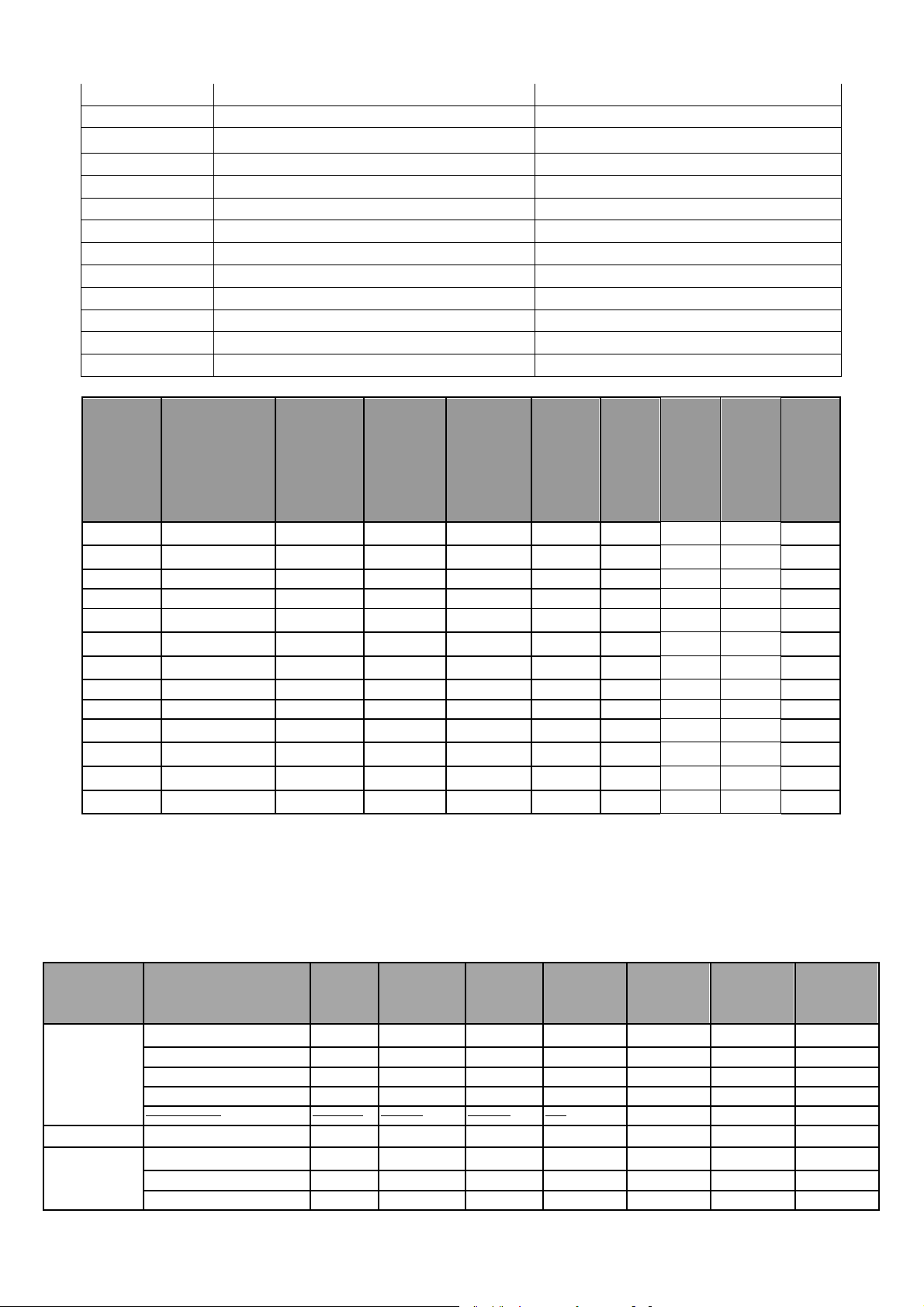
Pin HDMI Signal
MHL Signal
1 TMDS Data2+
N/C
2
TMDS Data2 Shield
CD_SENSE
3
TMDS Data2
– N/C
4 TMDS Data1+
N/C
5 TMDS Data1 Shield
TMDS_GND
6
TMDS
Data1
– N/C
Pb DATA
2
Support Timings: (Version 05)
Timing Resolution
Horizontal
frequency (KHz)
1.1.4 BNC *5 Input ( RGBHV ) NA
1.1.5 HDMI/DVI/MHL* Input
- HDMI 1.4 Compliance
- DVI 1.0 Compliance
- HDCP 1.4 Compliance
- MHL 2.1 Compliance
(1) Pin definition
Vertical
Frequency (Hz)
Dot Clock
Frequency (MHz)
Supported
Sequential
◎
◎
◎
17
7 TMDS Data0+
MHL+
8
TMDS Data0 Shield
MHL Shield
9
TMDS Data0
– MHL
-
10
TMDS Clock+
N/C
11
TMDS Clock Shield
TMDS_GND
12
TMDS Clock
– N/C
13
CEC
N/C
14
Reserved (N.C. on device)
N/C
15
SCL CD_PULLUP
16
SDA
N/C
17
DDC/CEC Ground
VBS_CBUS_GND
18
+5 V Power (max 50 mA)
VBUS
19
Hot Plug Detect
CBUS
User Manual
3D Field
3D
frame packing
3D
3D
480i *
720(1440) x 480
15.73
59.94
27
Yes
480p
720 x 480
31.47
59.94
27
Yes
576i *
720(1440) x 576
15.63
50 27
Yes 576p
720 x 576
31.25
50 27
Yes 720/50p
1280 x 720
37.5 50 74.25
Yes
◎ ◎
720/60p
1280 x 720
45.00
60
74.25
Yes
◎ ◎
1080/24P
1920 x 1080
27 24 74.25
Yes
◎ ◎
1080/25P
1920 x 1080
28.13
25
74.25
Yes 1080/30P
1920 x 1080
33.75
30
74.25
Yes 1080/50i
1920 x 1080
28.13
50
74.25
Yes
1080/60i
1920 x 1080
33.75
60
74.25
Yes
1080/50P
1920 x 1080
56.25
50
148.5
Yes
1080/60P
1920 x 1080
67.5 60
148.5
Yes
Refresh
H-
User Manual
3D Field
3D
3D
VGA_60
59.940
31.469
25.175
Yes
◎ ◎
VGA_72
72.809
37.861
31.500
Yes
VGA_75
75.000
37.500
31.500
Yes
VGA_85
85.008
43.269
36.000
Yes
VGA_120**
119.518
61.910
52.500
Yes
720 x 400
720x400_70
70.087
31.469
28.3221
Yes
SVGA_60
60.317
37.879
40.000
Yes
◎ ◎
SVGA_72
72.188
48.077
50.000
Yes
SVGA_75
75.000
46.875
49.500
Yes
(2) Support Video Timings: (Version 05)
Horizontal
Timing Resolution
frequency
(KHz)
Vertical
frequency
(Hz)
Dot Clock
Frequency
(MHz)
Supported
Sequential
over-under
side-by-side
◎
◎
◎
◎
◎
◎
◎
◎
◎
◎
◎
◎
Note :
MHL Not support 3D format.
* means the video format timing shall be transmitted using pixel repetition. The “pixel per line” count
is show according to the syntax used in EIA/CEA-861E.
(3) Support PC Timings: (Version 05)
Resolution Mode
640 x 480
800 x 600
rate
(Hz)
frequency
(kHz)
Clock
(MHz)
18
Supported
Sequential
◎
◎
overunder
sideby-side
SVGA_85
85.061
53.674
56.250
Yes
SVGA_120
Yes
1024 x 768
XGA_60
60.004
48.363
65.000
Yes
◎ ◎
XGA_70
70.069
56.476
75.000
Yes
XGA_75
75.029
60.023
78.750
Yes
XGA_85
84.997
68.667
94.500
Yes
XGA_120
Yes
1152 x 864
1152 x 864_75
75.00
67.500
108.000
Yes
1024x576
BenQ Notebook Timing
60.00
35.820
46.996
Yes
1024x600
BenQ Notebook Timing
64.995
41.467
51.419
Yes
1280 x 720_60
60
45.000
74.250
Yes
◎ ◎
1280x720_120
120 90.000
148.500
No
1280 x 768_60
No
1280 x 768_60
59.870
47.776
79.5 Yes
◎ ◎
WXGA_60
59.810
49.702
83.500
Yes
◎ ◎
WXGA_75
74.934
62.795
106.500
Yes
WXGA_85
84.880
71.554
122.500
Yes
WXGA_120
Yes
SXGA_60
60.020
63.981
108.000
Yes
◎
SXGA_75
75.025
79.976
135.000
Yes
SXGA_85
85.024
91.146
157.500
Yes
1280 x 960_60
60.000
60.000
108 Yes
◎
1280 x 960_85
85.002
85.938
148.500
Yes
1360 x 768
1360 x 768_60
60.015
47.712
85.500
Yes
◎
WXGA+_60
No
WXGA+_60
59.887
55.935
106.500
Yes
◎
1400X1050
SXGA+_60
59.978
65.317
121.750
Yes
◎
1600x1200
UXGA
60.000
75.000
162.000
Yes
1680x1050_60
No
1680x1050_60
59.954
65.290
146.250
Yes
◎
640x480
Yes
832x624
Yes
1024x768
Yes
1152x870
Yes
1920x1080
1920X1080_60
Yes
1920x1200@6
1920X1200_60
Yes
1920X1080(VE
1920X1080_60
no
(Reduce Blanking)
119.854 77.425 83.000
◎
◎
1280x720
1280 x 768
1280 x 800
1280 x 1024
1280 x 960
1440 x 900
(Reduce Blanking)
(Reduce Blanking)
(Reduce Blanking)
(Reduce Blanking)
119.989 97.551 115.500
60 47.396 68.25
119.909 101.563 146.25
60 55.469 88.75
◎
◎
◎
◎ ◎ ◎
◎
◎
◎
◎
◎
◎
◎ ◎
◎
◎
◎
1680x1050
@67Hz
@75Hz
@75Hz
@75Hz
@60HZ
0HZ
SA)
(Reduce Blanking)
MAC13 66.667 35.000 30.240
MAC16 74.546 49.722 57.280
MAC19 75.020 60.241 80.000
MAC21 75.06 68.68 100.00
(Reduce Blanking)
(Reduce Blanking)
(for Auditorium model)
59.883 64.674 119.000
60 67.5 148.5
59.95 74.038 154
59.963 67.158 173
(4) Support Audio:
(a) HDMI Mode:
- Support LPCM, two audio channels
- Support audio sampling rate : 32kHz, 44.1kHz, 48kHz
- Support audio bit rate : 16 bits, 20 bits, 24 bits
◎ ◎
◎
19
(b)MHL mode:
Pin Signal
Parameter
Min Type Max 1
RDATA
Impedance
75
Ohm
2
Amplitude
0.7
Volts peak
-to-
peak 3 Black pedestal
0
Volts
Pixel Clock
170
M Hz
2 GDATA_SOG
Impedance
75
Ohm
Amplitude
1
Volts peak
-to-
peak Video
amplitude
0.7
Volts peak
-to-
peak Sync amplitude
0.3
Volts peak
-to-
peak Black pedestal
0
Volts Pixel Clock
170
M Hz
HDATA
Impedance
1
K ohm
Amplitude, low level
0 0.5 volt
Amplitude, high level
2.5 5
Volt Frequency
31 102 K Hz
VDATA
Impedance
1
K ohm
Amplitude, low level
0 0.8 volt Amplitude, high level
2.5 5
Volt Frequency
48 120 Hz
SDADATA
Amplitude, low level
0 0.8 volt Amplitude, high level
2.5 5
Volt
SCLDATA
Amplitude, low level
0 0.8 volt Amplitude, high level
2.5 5
Volt 4 NC 5 NC 6 Red GND
7 Green GND
8 Blue GND
9 DDCP 5V
5 Volts 10 Sync. Return
11 GND
2 G DATA
Amplitude (with sync)
1
Volts peak to peak
Impedance
75
ohm
1 R DATA
Amplitude
0.7
Volts peak to peak
Impedance
75
ohm
3 B DATA
Amplitude
0.7
Volts peak to peak
Impedance
75
ohm
-Support LPCM, two audio channels (follow IEC 60958 and IEC 61937)
-Support audio sampling rate : 32kHz, 44.1kHz, 48kHz
- Support audio bit rate : 16 bits, 20 bits, 24 bits
(C) DVI Mode:
Analog audio is supported through PC audio input terminal.
Note. There timing showing depend the EDID file and VGA graphic card limitation.
It is possible that user cannot choose the above timings on VGA display card.
1.1.6 PC Input
(1) Pin definition and Signal Level:
GDATA
BDATA
13
14
12
15
Share with Y
Share with Pr
Share with Pb
20
(2) Support PC Timings: (Version 05)
H-
User
3D Field
3D
3D
720 x 400
720x400_70
70.087
31.469
28.3221
Yes
VGA_60
59.940
31.469
25.175
Yes
◎ ◎
VGA_72
72.809
37.861
31.500
Yes
VGA_75
75.000
37.500
31.500
Yes
VGA_85
85.008
43.269
36.000
Yes
VGA_120**
119.518
61.910
52.500
Yes
SVGA_56
56.250
35.156
36.000
Yes
SVGA_60
60.317
37.879
40.000
Yes
◎ ◎
SVGA_72
72.188
48.077
50.000
Yes
SVGA_75
75.000
46.875
49.500
Yes
SVGA_85
85.061
53.674
56.250
Yes
SVGA_120
Yes
XGA_60
60.004
48.363
65.000
Yes
◎ ◎
XGA_70
70.069
56.476
75.000
Yes
XGA_75
75.029
60.023
78.750
Yes
XGA_85
84.997
68.667
94.500
Yes
XGA_120
Yes
1152 x 864
1152 x 864_75
75.00
67.500
108.000
Yes
1024 x 576
BenQ NB Timing
60.0 35.820
46.966
Yes
1024 x 600
BenQ NB Timing
64.995
41.467
51.419
Yes
1280 x 720_60
60
45.000
74.250
Yes
◎ ◎
1280x720_120
120 90.000
148.500
No
◎
1280 x 768_60
No
1280 x 768_60
59.870
47.776
79.5
Yes
◎ ◎
WXGA_60
59.810
49.702
83.500
Yes
◎ ◎
WXGA_75
74.934
62.795
106.500
Yes
WXGA_85
84.880
71.554
122.500
Yes
WXGA_120
Yes
SXGA_60
60.020
63.981
108.000
Yes
◎
SXGA_75
75.025
79.976
135.000
Yes
SXGA_85
85.024
91.146
157.500
Yes
1280 x 960_60
60.000
60.000
108
Yes ◎ ◎
1280 x 960_85
85.002
85.938
148.500
Yes
1360 x 768
1360 x 768_60
60.015
47.712
85.500
Yes ◎ ◎
WXGA+_60
No
WXGA+_60
59.887
55.935
106.500
Yes ◎ ◎
1400X1050
SXGA+_60
59.978
65.317
121.750
Yes ◎ ◎
1600x1200
UXGA
60.000
75.000
162.000
Yes ◎ ◎
1680x1050_60
No
1680x1050_60
59.954
65.290
146.250
Yes ◎ ◎
640x480
Yes
832x624
Yes
Resolution Mode
640 x 480
800 x 600
(Reduce Blanking)
1024 x 768
(Reduce Blanking)
Refresh
rate (Hz)
119.854 77.425 83.000
119.989 97.551 115.500
frequency
(kHz)
Clock
(MHz)
Manual
Supported
Sequential
◎
◎
◎
◎
◎
overunder
sideby-side
1280x720
1280 x 768
1280 x 800
1280 x 1024
1280 x 960
1440 x 900
(Reduce Blanking)
(Reduce Blanking)
(Reduce Blanking)
60 47.396 68.25
119.909 101.563 146.25
60 55.469 88.75
◎
◎ ◎ ◎
◎
◎
◎
◎
◎ ◎
1680 x 1050
@67Hz
@75Hz
(Reduce Blanking)
MAC13 66.667 35.000 30.240
MAC16 74.546 49.722 57.280
59.883 64.674 119.000
21
◎ ◎
1024x768
@75Hz
Yes
1152x870
Yes
1920x1080
1920X1080_60
Yes
1920X1200_60
Yes
1920X1080_60
no
PIN Signal
Parameter
Min Type Max 1
L Audio
Amplitude
0.5 2 VRMS
Impedance
10
KΩ
Amplitude
0.5 2 VRMS
Impedance
10
KΩ
PIN Signal
Parameter
Min Type Max 1
GND
2 Audio In Left
Amplitude
0.5 2 VRMS
Impedance
10
KΩ 3 NC 4 NC 5 Audio In Right
Amplitude
0.5 2 VRMS
Impedance
10
KΩ
MAC19 74.93 60.241 80.000
@75Hz
@60HZ
1920x1200@60HZ
1920X1080(VESA)
MAC21 75.06 68.68 100.00
(Reduce Blanking)
(Reduce Blanking)
(for Auditorium
model)
60 67.5 148.5
59.95 74.038 154
59.963 67.158 173
Note. There 3D timing showing depend the EDID file and VGA display card. It is possible that user cannot
choose the above 3D timings on VGA display card.
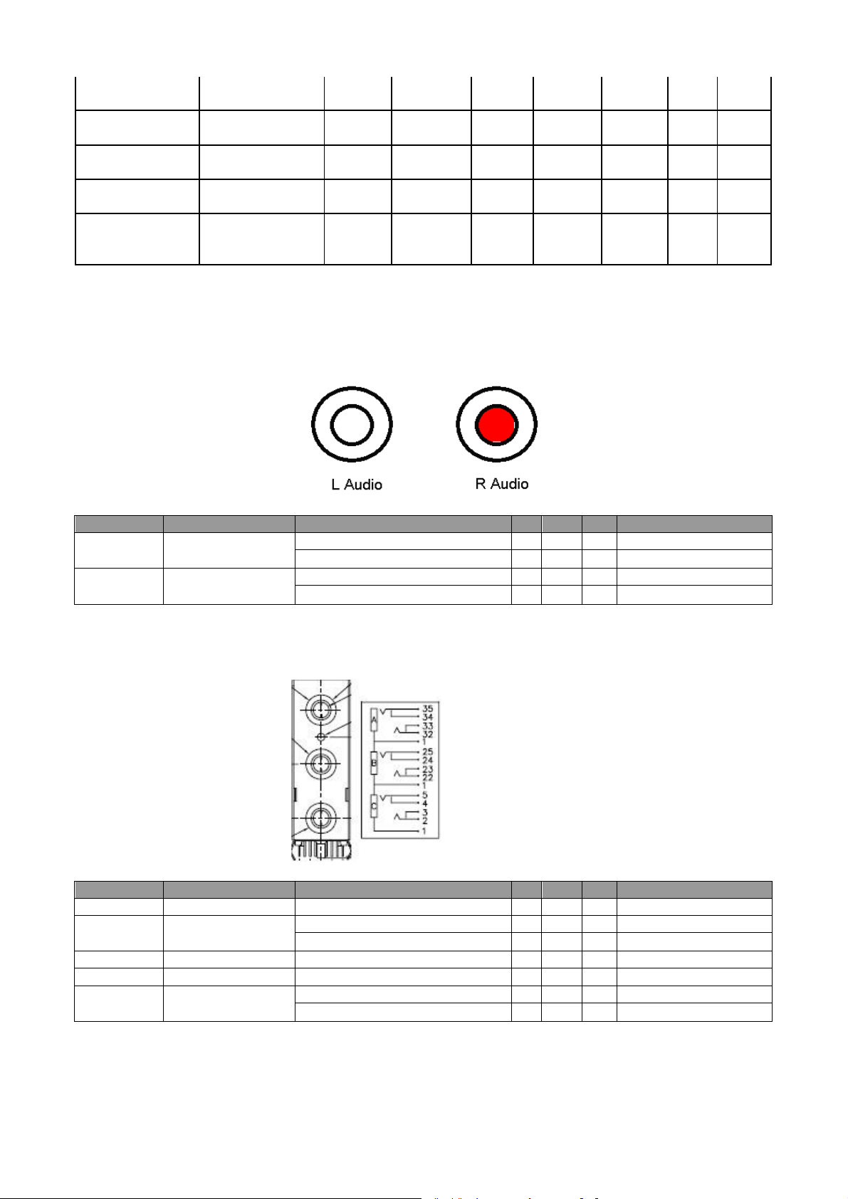
1.1.7 Audio Input (RCAx2)
(1) Pin definition :
(2) Signal Level: N/A
2 R Audio
1.1.8 Audio Input (Mini-Jack φ3.5mm)
(1) Pin definition
(2) Signal Level:
22
1.1.9 Audio Headphone Output (Phone-Jack φ3.5mm)
PIN Signal
Parameter
Min Type Max
25 Audio Out Right
Amplitude
400 500 600 mV ( when input =
Load Impedance
32
10kohm
Audio out detect
Output ON
0.2 VDD
Output Off
0.8 VDD
Audio Out Left
Amplitude
400 500 600 mV ( when input =
Impedance
32
10kohm
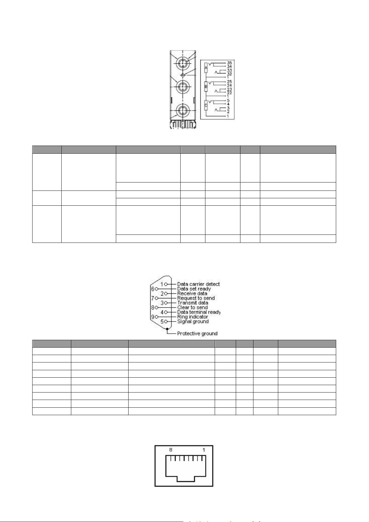
PIN Signal
Parameter
Min Type Max 1 NC 2 RX Amplitude (with sync)
-25 25
Volt 3 TX Amplitude
-13.2
13.2 Volt 4 NC 5
GND
6 NC 7
RTSZ
8 CTSZ
9 NC
(1) Pin definition
(2) Signal Level:
23/24
22
1.1.10 RS232 Control Port
(1) Pin definition (D-Sub 9 Pin)
(2) Signal Level:
500mVrms , volume
maximum and Measurement
on 10kohm loading)
Ω
500mVrms , volume
maximum and Measurement
on 10kohm loading)
Ω
1.1.11 Lan Control Port (Follow IEEE 802.3)
(1) Pin definition(speed:10M/100M)
(2) Signal Level:
23
PIN Signal
1
TD+ 2 TD- 3
RD+ 4 Common Mode Termination
5
Common Mode Termination
6 RD- 7 Common Mode Termination
8
Common Mode Termination
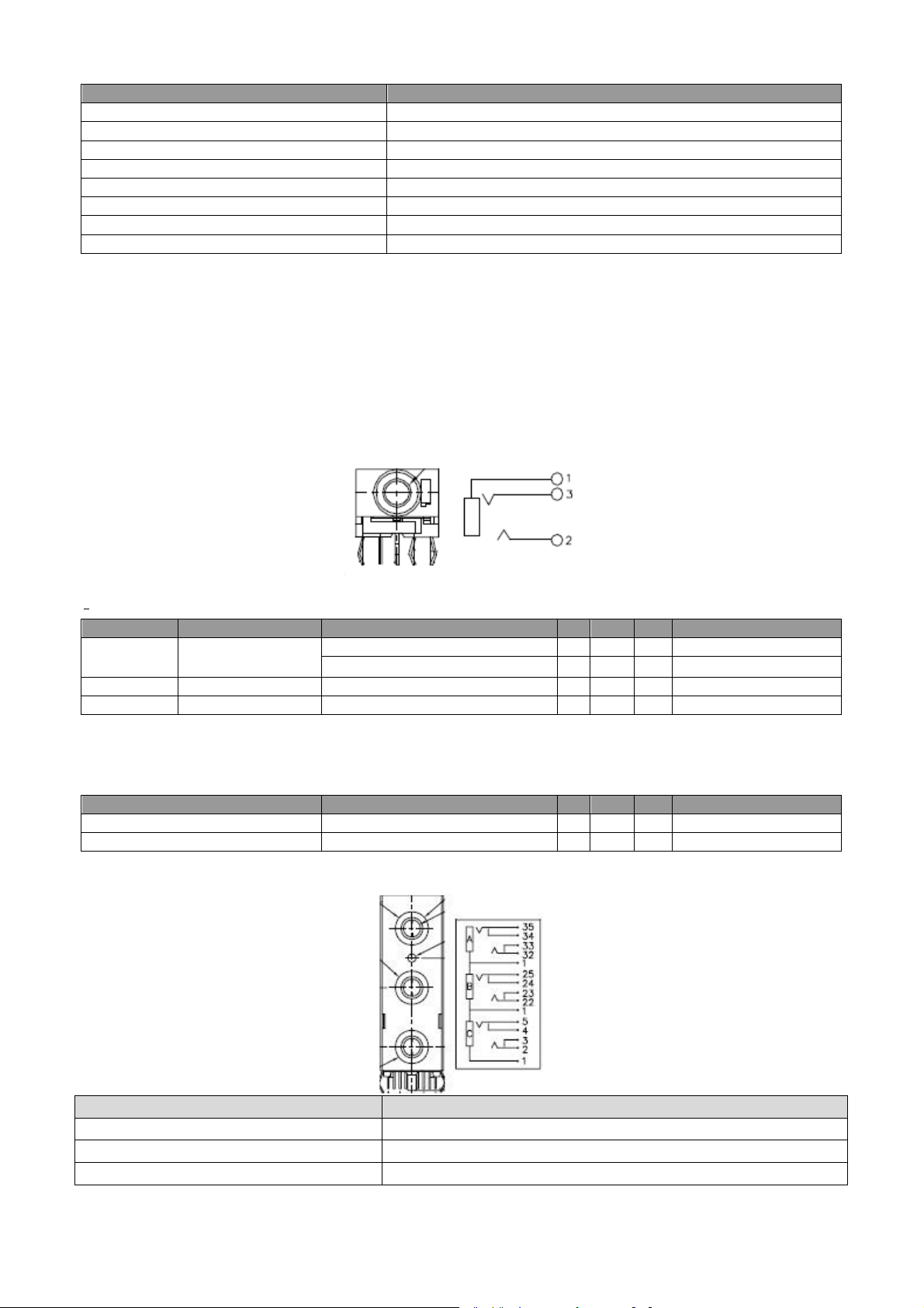
PIN Signal
Parameter
Min Type Max
Amplitude
12 V
Current
500
mA 3
Ring 1
GND
Signal
Parameter
Min Type Max
I hode
0.5 A
I trip
1.0 A
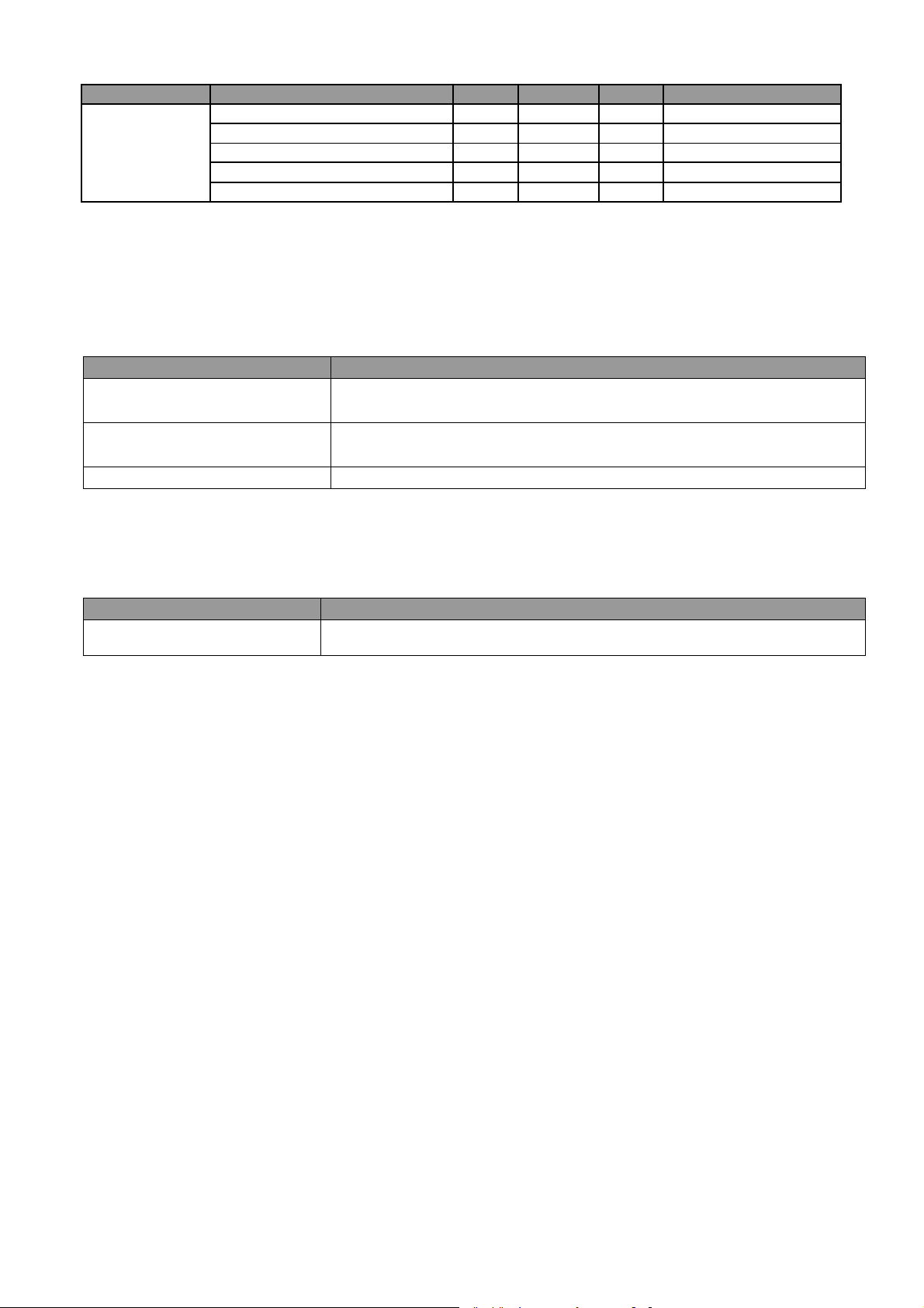
Pin Pin Define
33/35
GND
32
Mic_Hot_in
34
MIC_DET
Lan LED information for A-Top :
LED define as following:
Green => Link LED . Solid on , Network connection is normally.
Yellow => Operation LED
Flash, 4 sec on/off, MCU is working normally.
Flash 0.5 sec on/off, FW Download mode.
1.1.12 Screen control output (3.5mm jack )
(2) Signal Level:
2 DC
(2) Overload Protection:
- Reversible Fuse.
1.1.13 Microphone
1.2 Speaker
24
Signal
Parameter
Min Type Max
Audio
Impedance (audio in)
10
Kohm
Amplitude (audio in)
500
mVolts rms
Bandwidth
300Hz
16kHz
S/N Ratio
40 dB
Total Harmonic Distortion
10 %
Specification
Description
Input Voltage Range
The unit shall meet all the operating requirements
with the range 90
Frequency Range
The unit shall meet all the operating requirements with an input
Regulation Efficiency
80 % (typical) measuring at 115Vac and full load
Specification
Description
Starting pulse from Igniter
3.5kV
Power Supply Specification
1.1 Input Power Specification
~ 264 VAC
frequency range 47 Hz ~ 63 Hz
1.2 Varistor Requirement
The power supply’s varistor component should stand 510V or higher power.
1.3 Lamp Power Requirement
25
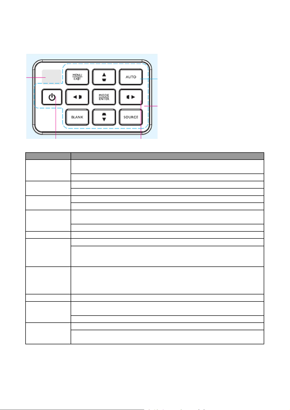
UI Specification
Key Name
Detailed Description
Left/Keystone
1. When user press the button once, it will decrease the keystone horizontal
2. If there is SOD menu, user can press this key to move to the left item
Right/Keystone
1. When user press the button once, it will increase the keystone
horizontal value
2. When there is OSD menu, user can press this key to move to right item
Up/Keystone+
1. When user presses the bottom once, it will increase the vertical keystone value
2. When there is OSD menu, user can press this key to move to
upper item
Down/Keystone
- 1. When user presses this bottom once, it will decrease the vertical keystone
2. When there is OSD menu, user can press this key to move to next item
Source
Switch to next source
Power
1. User presses this key once to
turn on projector
2. When projector is on, user should press this key once and show confirm
Auto
Auto adjusts the most suitable frequency, phase, for the
input source. User could
Blank
This button will turn projecto
r into/out of
blank mode.
Mode/Enter
1. When there is no OSD menu, this button is Mode hot key, user would press
2. When there is confirm message, user could press this key to confirm
Menu/Exit
1. User could
press this bottom to call out OSD
2. When it exits OSD, user could press this bottom to leave current page or items
Keypad Description
Key Action Definition
value
value
message; then user should press "Power" key again to turn off projector (LED
would be blink orange)
get the optimal projection quality by pressing the button. Auto-Adjustment
function will not influence the color or brightness setting by users. “Auto” will
only be active on PC (VGA) source.
this button to choose one of preset modes.
or to close OSD.
26
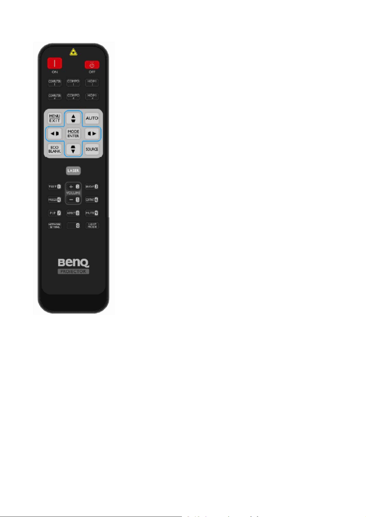
Remote Control Function and Key Code Definition (Detail See Appendix2)
27
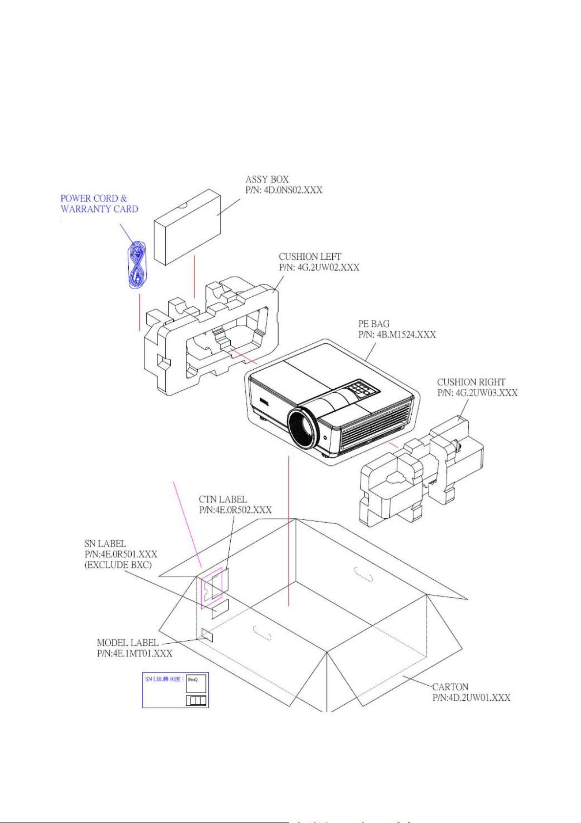
3.2 Packing
Put Power Cord & Warranty Card
【NOTE】The updated Service BOM is on SPO system. Please check it to order service parts.
1. For 9H.JEG77.15X:
->Seal Doggy Door -> Paste CTN
Label
28
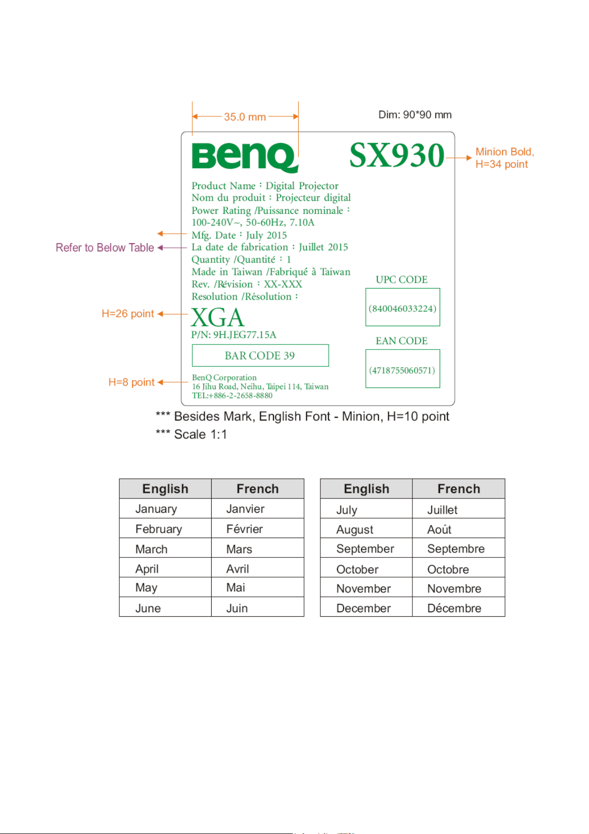
CTN LBL PRINTING:
Actual Date
1. For 9H.JEG77.15A
29
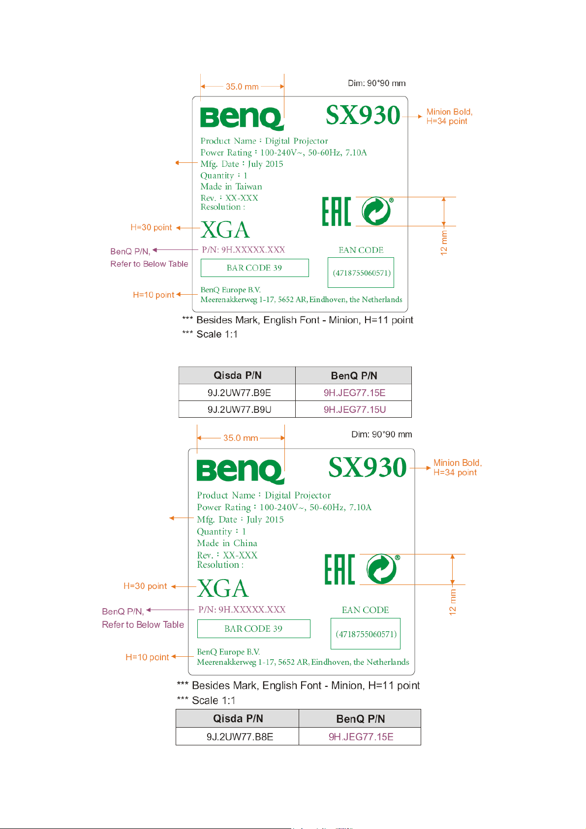
3. For 9H.JEG77.15E/15U
Actual Date
Actual Date
30
 Loading...