


Recycle Disassemble Instruction
(Dismantled Information)
Requirements according to ANNEX VII of DIRECTIVE 2012/19/EU
on waste electrical and electronic equipment (WEEE)
Materials and components with hazardous content
LCDs may contain hazardous substances like Pb and BFRs which are covered by
exemptions under the RoHS directive. However, the majority is present in the printed
circuit boards assembly. In order to reduce emissions as much as possible, a complete
disposal of the old appliance is required. This treatment may only be performed in
authorized handling plants.
Product Name: Interactive flat panel
Model No.: RE7501

Disassembly Tools
Tool
picture
Philips Screwdriver for M3
screw
nosed pliers
Diagonal Cutting Pliers
Slotted screwdriver
Six Point Sockets
Philips Screwdriver for M2.5
screw
knife

Disassembly process
Remove 13 screws that
M4 ×6mm flat
head nickel plated
mechanical screw
1.Remove 6 screws that
M3 ×11mm flat head
nickel plated mechanical
screw.
2.Remove 1 screw that
M3 ×6mm countersunk
head nickel-plated
mechanical screw
Remove 16 screws that
M3 ×6mm meson head
nickel-plated mechanical
screw.
1.Remove 12 screws
that M4 ×6mm flat
head nickel-plated
mechanical screw
2.Remove the rear cover
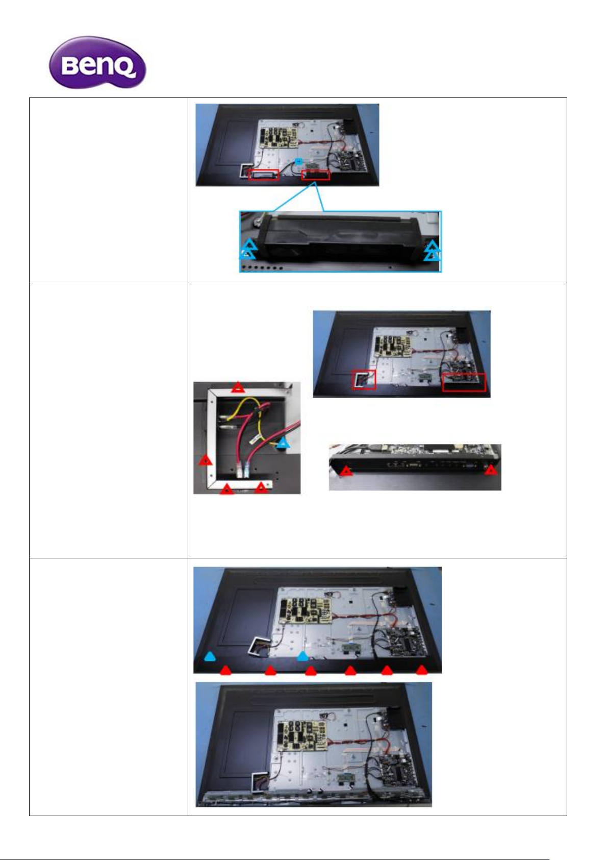
1.Pull the horn line
2.Remove 8 screws that
M3×6mm P head with
spring pad with flat pad
coated with blue zinc
mechanical screw.
3.Remove the horns
1.Remove 6 screws
that M4 ×6mm flat
head nickel-plated
mechanical screw
2.Remove 1 screws
that Ф 4 x 5 mm round
head toothed pads
blue zinc plating
machine screws
3.Remove the Switch
bracket and IO baffle
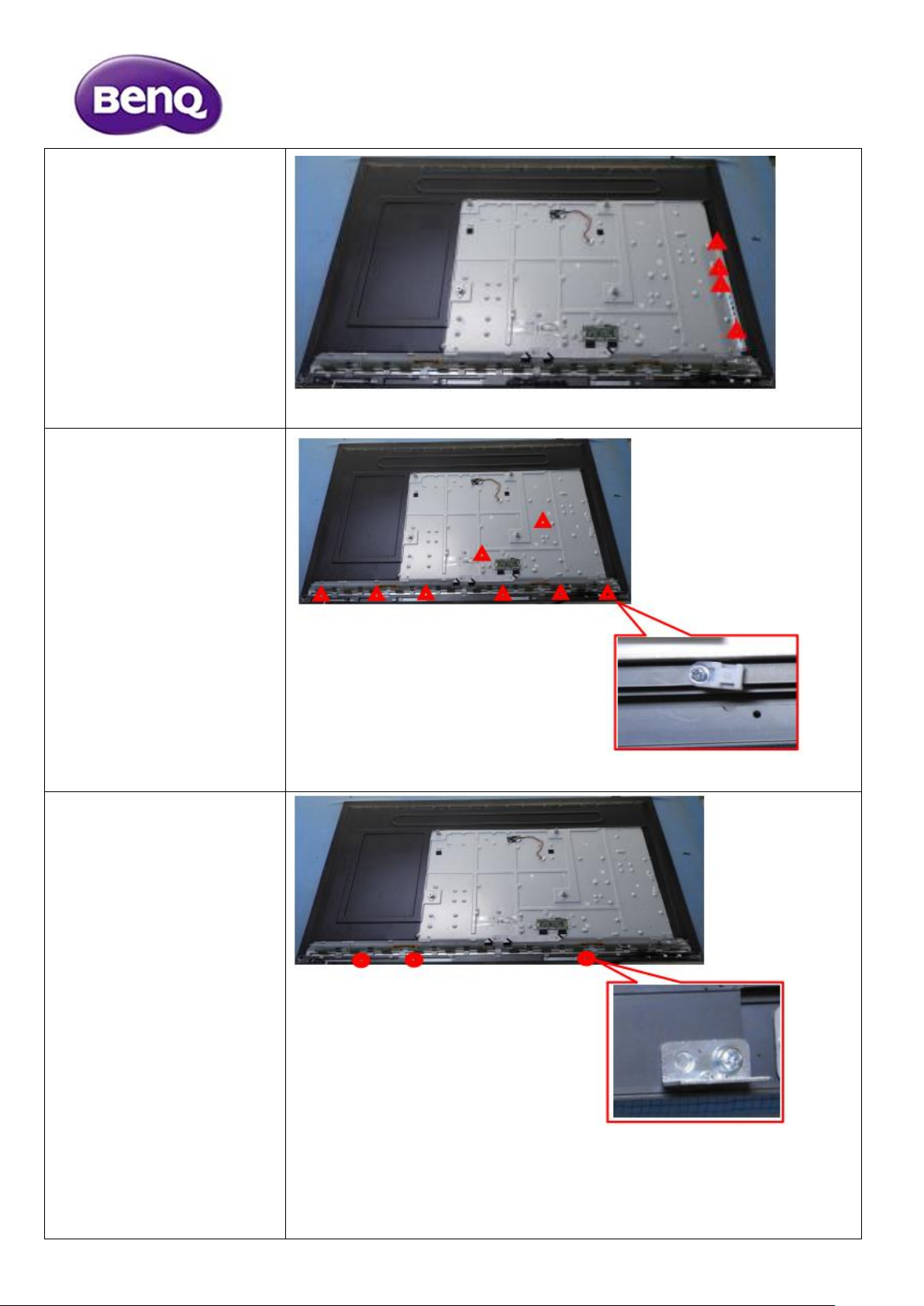
1.Remove 6 screws that
M3 ×6mm meson
head nickel-plated
mechanical screw
2.Remove 2 screws that
M4 ×6mm flat head
nickel-plated mechanical
screw
3.Remove the back shell

1.Remove The main
board
2.Remove OPS adapter
plate
3.Remove The power
supply board
1.Remove 4 screws that
M3×4mm meson head
nickel-plated mechanical
screw
2.Remove 2 screws that
M3×6mm P head with
spring pad with flat pad
coated with blue zinc
mechanical screw
3.Remove OPS guide
bracket and WIFI board
fixed bracket
1.Remove 4 screws that
M3×6mm P head with
spring pad with flat pad
coated with blue zinc
mechanical screw.
2.Remove 1 screw that
Φ 3 * 3.0 * 4 mm
resistance to fall outside
the hexagon blue zinc
plated screws.
3.Remove the OPS
mounting bracket
1.Remove 4 screws that
Φ 3 x 6 countersunk
head black zinc plating
machine screws
2.Remove IO side baffle
1.Remove 8 screws that
M3×6mm P head with
spring pad with flat pad
coated with blue zinc
mechanical screw
2.Remove The Cable tie
fixed seats
1.Remove 3 screws that
M3×6mm P head with
spring pad with flat pad
coated with blue zinc
mechanical screw
2.Remove Rear cover
support frames

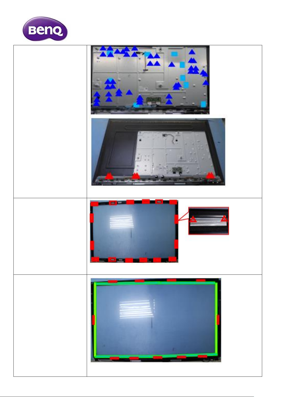
1.Remove 16 screws
that M3×6mm P head
with spring pad with flat
pad coated with blue
zinc mechanical screw.
2.Remove Screen fixing
brackets.
3.Tear off the masking
mylar.
1.Remove 2 screws that
M3×6mm P head
with spring pad with flat
pad coated with blue
zinc mechanical screw.
2.Remove 1 screw that
M4 ×5mm round head
with tooth pad plain tail
plated with blue zinc
mechanical screw.
3.Remove Front plate
support
1.Remove 2 screws that
M3×6mm P head
with spring pad with flat
pad coated with blue
zinc mechanical screw.
2.Remove Press the key
plate support
1.Remove 48 screws
that M3×6mm P head
with spring pad with flat
pad coated with blue
zinc mechanical screw.
2.Remove 6 screws that
M4 ×6mm round
head flat tail with spring
pad plated with blue zinc
mechanical screw.
3.Tear off 10 lightblocking mylar tablets
1.Remove 32 screws
that M3 ×3.3mm
countersunk head plated
with blue zincmechanical
screw.
2.Remove glass
preforms
1. Tear the foam pad off
the glass.
2.Tear off the EVA pad
(
100 ×10 ×1.5mm
)
attached to the frame
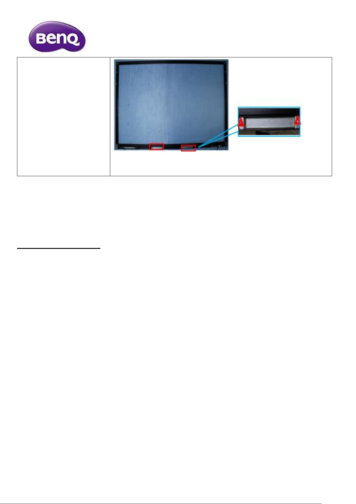
1. Remove 4 screws that
M3×6mm P head with
spring pad with flat pad
coated with blue zinc
mechanical screw.
2.Remove holders for
fixed stylus pen
Disassembly Time
Total time: about 35 minutes
 Loading...