

Page 1

MP778/MP780 ST
Digital Projector
User Manual
Welcome
Page 2

Table of contents
Important safety
instructions .........................3
Introduction........................7
Projector features .................................. 7
Positioning your projector16
Connection .......................21
Operation ..........................30
Maintenance......................83
Troubleshooting ...............90
Specifications ....................91
Warranty and Copyright
information .......................96
Regulation statements ......97
Shipping contents.................................. 8
Projector exterior view........................ 10
Controls and functions ....................... 11
Choosing a location............................. 16
Obtaining a preferred projected image
size........................................................ 17
Connecting a computer or monitor... 23
Connecting Video source devices....... 26
Operating in a high altitude
environment.........................................45
Adjusting the sound.............................46
Personalizing the projector menu
display...................................................47
Controlling the projector through a LAN
environment.........................................47
Displaying image through Q Presenter57
Presenting From a USB Reader...........61
Remote Desktop Control through Q
Presenter...............................................64
PointDraw
Shutting down the projector ...............69
Menu operation ...................................70
Care of the projector............................83
Lamp information................................84
TM
Pen (MP780 ST only)....66
Starting up the projector..................... 30
Adjusting the projected image ............ 31
Using the menus.................................. 33
Securing the projector......................... 34
Switching input signal......................... 36
Magnifying and searching for details . 37
Selecting the aspect ratio..................... 37
Optimizing the image.......................... 39
Creating your own startup screen ...... 42
Setting the presentation timer ............ 43
Remote paging operations .................. 43
Hiding the image ................................. 44
Freezing the image............................... 44
Utilizing FAQ function ....................... 44
Locking control keys ........................... 45
2
Dimensions...........................................92
Ceiling mount installation...................92
Timing chart.........................................93
Page 3
Important safety instructions
Your projector is designed and tested to meet the latest standards for safety of information
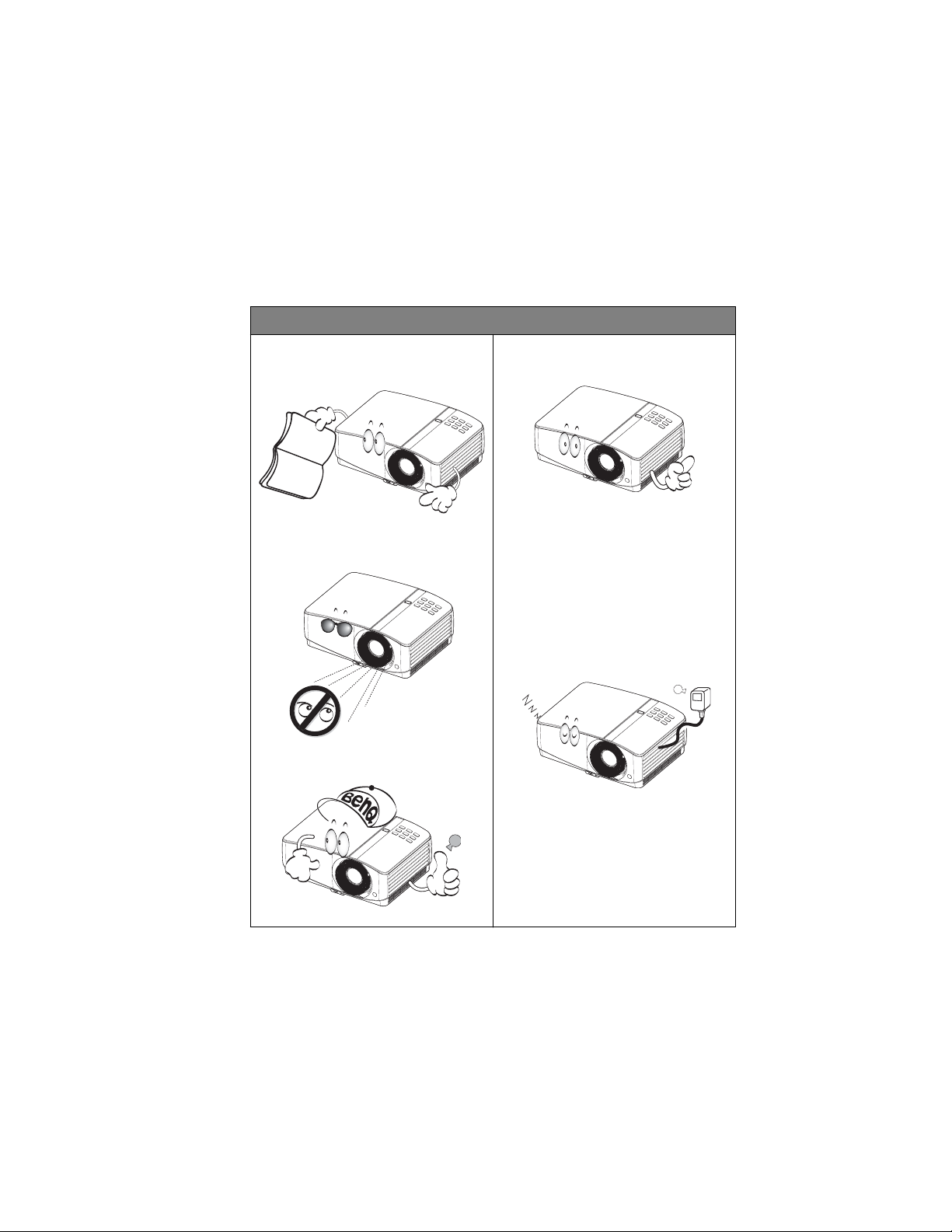
Please read this manual before you
operate your projector.
Do not look straight at the projector
lens during operation.
Refer servicing to qualified service
personnel.
Always open the lens shutter or
remove the lens cap when the
projector lamp is on.
In areas where the
mains voltage may fluctuate or cut
out, it is recommended that you
connect your pr
ojector through a
power stabilizer, surge protector or
uninterruptible power supply (UPS).
BLANK
technology equipment. However, to ensure safe use of this product, it is important that you
follow the instructions mentioned in this manual and marked on the product.
Safety Instructions
1. P
future reference.
4. A
Save it for
2. D
light beam may damage your eyes.
3. R
The intense
5. In some countries, the line voltage is
NOT stable. This projector is designed
to operate safely within a mains
voltage between 100 to 240 volts AC,
but could fail if power cuts or surges
of r10 volts occur. I
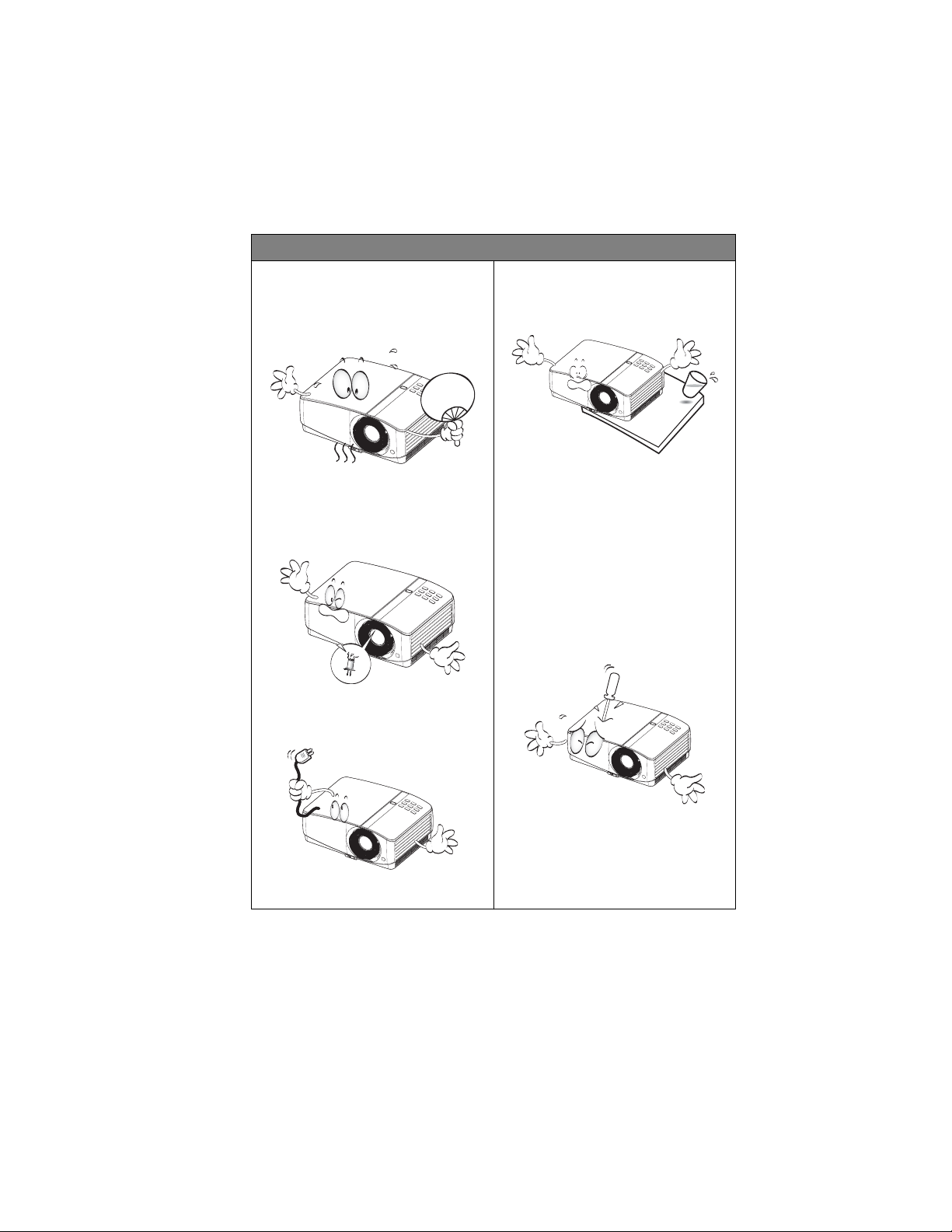
6. Do not block the projection lens with
any objects when the projector is
under operation as this could cause
the objects to become heated and
deformed or even cause a fire. To
temporarily turn off the lamp, press
control.
on the projector or remote
Important safety instructions 3
Page 4
Safety Instructions (Continued)
7. The lamp becomes extremely hot
during operation. Allow the
projector to cool for approximately
45 minutes prior to removing the
lamp assembly for replacement.
10. Do not place this product on an
unstable cart, stand, or table. The
product may fall, sustaining serious
damage.
8. Do not operate lamps beyond the
rated lamp life. Excessive operation
of lamps beyond the rated life could
cause them to break on rare
occasions.
9. Never replace the lamp assembly or
any electronic components unless
the projector is unplugged.
11. Do not attempt to disassemble this
projector. There are dangerous high
voltages inside which may cause
death if you should come into
contact with live parts. The only
user serviceable part is the lamp
which has its own removable cover.
Under no circumstances should you
ever undo or remove any other
covers. Refer servicing only to
suitably qualified professional
service personnel.
12. When the projector is under
operation, you may sense some
heated air and odor from its
ventilation grill. It is a normal
phenomenon and not a product
defect.
Important safety instructions4
Page 5
Safety Instructions (Continued)
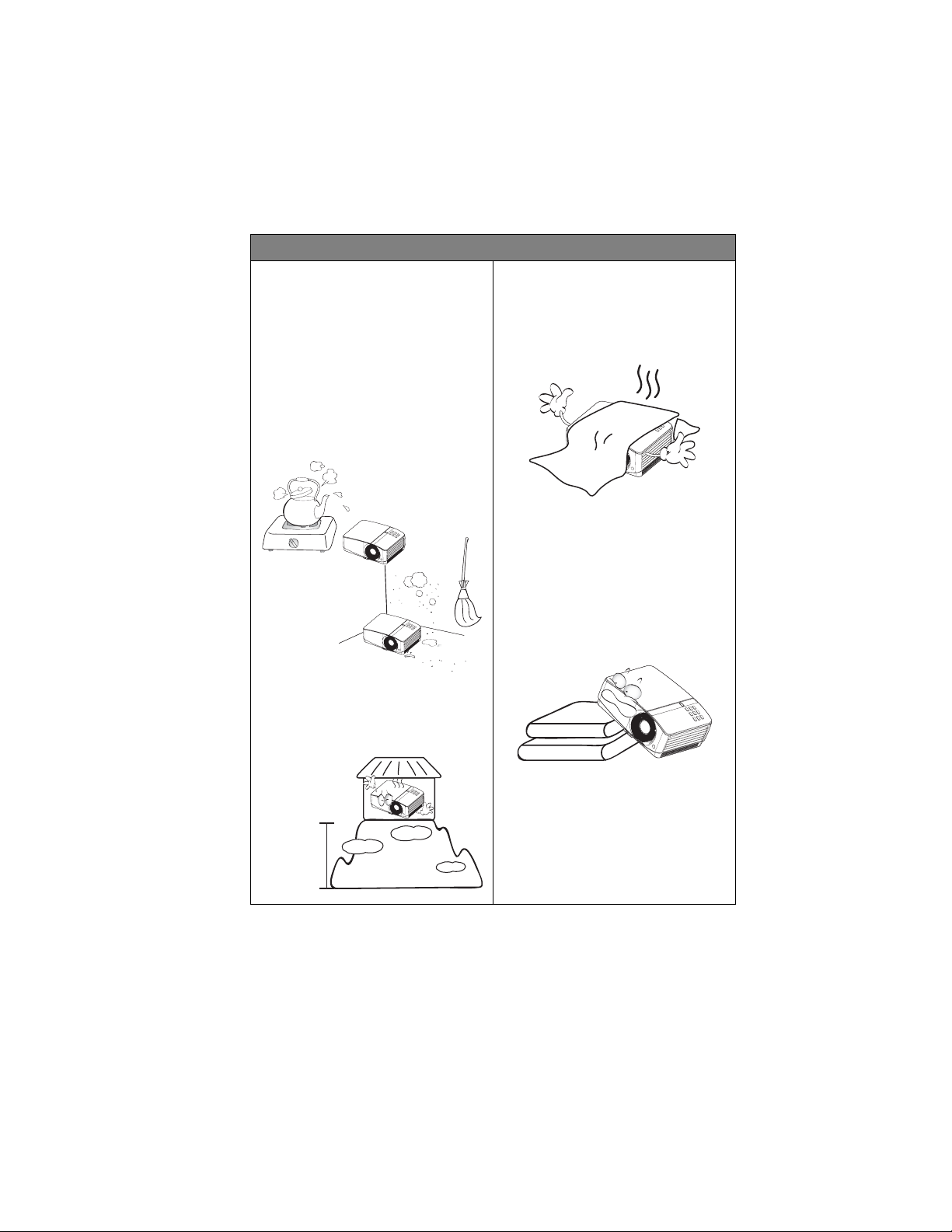
13. Do not place this projector in any of
the following environments.
- Space that is poorly ventilated or
confined. Allow at least 50 cm clearance
from walls and free flow of air around the
projector.
- Locations where temperatures may
become excessively high, such as the
inside of a car with all windows rolled up.
- Locations where excessive humidity, dust,
or cigarette smoke may contaminate
optical components, shortening the
projector's life span and darkening the
image.
- Locations near fire alarms
- Locations with an ambient temperature
above 40°C / 104°F
- Locations where the altitudes are higher
than 3000 m (10000 feet).
14. Do not block the ventilation holes.
- Do not place this projector on a blanket,
bedding or any other soft surface.
- Do not cover this projector with a cloth or
any other item.
- Do not place inflammables near the
projector.
If the ventilation holes are seriously
obstructed, overheating inside the
projector may result in a fire.
15. Always place the projector on a level,
horizontal surface during operation.
- Do not use if tilted at an angle of more
than 10 degrees left to right, nor at angle
of more than 15 degrees front to back.
Using the projector when it is not fully
horizontal may cause a malfunction of, or
damage to, the lamp.
3000 m
(10000 feet)
0 m
(0 feet)
Important safety instructions 5
Page 6
Safety Instructions (Continued)
16. Do not stand the projector on end
vertically. Doing so may cause the
projector to fall over, causing injury or
resulting in damage to the projector.
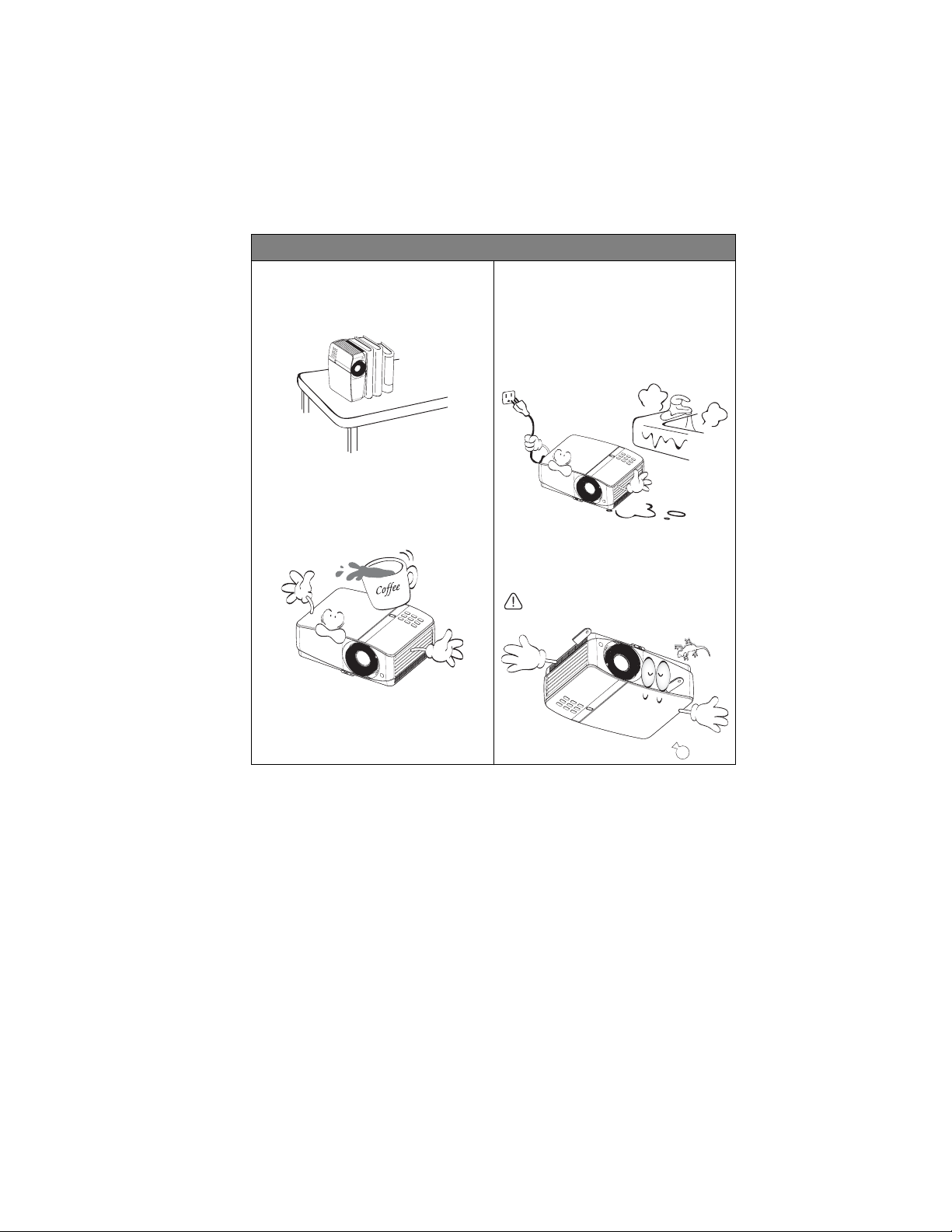
17. Do not step on the projector or place
any objects upon it. Besides probable
physical damage to the projector, doing
so may result in accidents and possible
injury.
18. Do not place liquids near or on the
projector. Liquids spilled into the
projector may cause it to fail. If the
projector does become wet, disconnect
it from the power supply's wall socket
and call BenQ to have the projector
serviced.
19. This product is capable of displaying
inverted images for ceiling mount
installation.
Use only BenQ's Ceiling Mount Kit for
mounting the projector and ensure it
is securely installed.
Important safety instructions6
Page 7

Introduction
Projector features
The projector integrates high-performance optical engine projection and a user-friendly
design to deliver high reliability and ease of use.
The projector offers the following features.
•HDMI
• LAN display for network control and web server
• LAN display 4-1 (maximum 4PC/ NB display to 1 projector)
• Remote desktop feature for LAN and USB display 1-M (maximum 1PC/ NB can display
to 8 projectors at the same time)
• USB display supports computer connection via USB mini-B type to A type cable
• USB Reader supports USB flash drive or HDD display
• 3D Ready supported
• Variable audio output
• Microphone input with big speakers (10W x2) can save extra audio systems for schools
• Wall color correction allowing projection on surfaces of several predefined colors
• Quick auto search speeding up the signal detecting process
• Selectable password protected function
• 3D color management allowing color adjustments to your liking
• Selectable quick cooling function makes the projector cool in a shorter time
• Presentation timer for better control of time during presentations
• One-key auto-adjustment to display the best picture quality
• Digital keystone correction to correct distorted images
• Adjustable color balance control for data/video display
• High brightness projection lamp
• Multi-language On-Screen Display (OSD) menus
• Switchable normal and economic modes to reduce the power consumption
• Component HDTV compatibility (YP
• Less than 1 W power consumption in standby mode
The MP778 also offers the following features.
• Big zoom ratio (1.6x) provides the installation flexibility
The MP780 ST also offers the following features.
TM
•PointDraw
• WXGA, perfect for widescreen NB and PC, and provides 30% more images to XGA
• Short throw lens to create larger images with less distance between the projector and the
screen
pen interactive projector
bPr)
• The apparent brightness of the projected image will vary depending on the ambient
lighting conditions, selected input signal contrast/brightness settings, and is directly
proportional to projection distance.
• The lamp brightness will decline over time and may vary within the lamp manufacturers
specifications. This is normal and expected behavior.
Introduction 7
Page 8
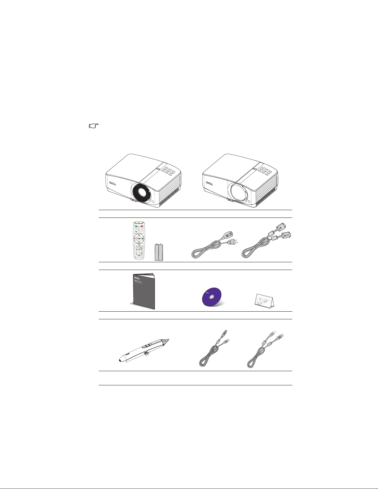
Shipping contents
Standard accessories
Carefully unpack and verify that you have all of the items shown below. If any of these items
are missing, please contact your place of purchase.
The supplied accessories will be suitable for your region, and may differ from those
illustrated.
*The warranty card is only supplied in some specific regions. Please consult your dealer for
detailed information.
MP778 projector MP780 ST projector
Remote control with batteries Power cord VGA cable
MP780 ST only
Introduction8
Quick start guide User manual CD Warranty card*
PointDraw
TM
pen
USB min i-B t ype to A
type cable
USB B type to A type
cable
Page 9
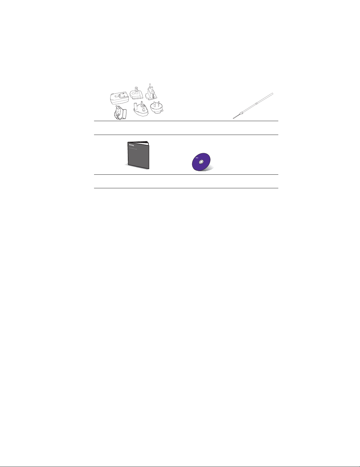
Optional accessories
USB power adapter
TBD
Poin tDraw
holder
TM
pen
Poin tDrawTM pen wrist
strap
TM
Poin tDraw
pen quick start guide
1. Spare lamp kit
2. Ceiling mount kit
3. Soft carry case (standard accessory
for MP778)
Q Draw interactive
software
4. RS232 cable
5. Wireless dongle
6. PointDraw
TM
pen
Introduction 9
Page 10

Projector exterior view
Front/upper side
(MP778)
Rear/lower side
1
2
3
4
5
(MP780 ST)
1
2
4
5
11
12
1. External control panel
(See "Projector" on page 11 for
details.)
2. Lamp cover
3. Focus ring (MP778)
Focus slide lever (MP780 ST)
4. Projection lens
5. Lens cover
6. Vent (heated air exhaust)
6
7. Speakers
8. Zoom slide lever (MP778 only)
7
9. Front IR remote sensor
8
10. Quick-release button
11. Audio output jack
9
12. Audio input jack
10
13. S-Video input jack
14. RGB signal output jack
15. RGB (PC)/Component video
(YPbPr/ YCbCr) signal input jack
16. HDMI input jack
17. RS-232 control port
18. USB B type jack
19. USB A type jack
6
20.
RJ45 LAN input jack
21. Rear IR remote sensor
22. Rear adjuster foot
7
23. USB mini-B type jack
3
24. Kensington anti-theft lock slot
9
25. Ceiling mount holes
10
26. 12V DC output terminal Used to
trigger external devices such as
anelectric screen or light control,
etc. Consult your dealer for how to
connect these devices.
13
14
17
1615
18
19
20
21
27. Video input jack
28. AC power cord inlet
29. Audio (L/R) input jack
30. Microphone input jack
10 24252627282930 23 22
Introduction10
Page 11

Controls and functions
Projector
6. AUTO
Automatically determines the best picture
7. Power/POWER indicator light
8. TEMPerature indicator light
9. Right/
10. LAMP indicator light
11. SOURCE
1. MENU/EXIT
2. Keystone/Arrow keys ( / Up, /
Down)
3. Left/
4. MODE/ENTER
5. BLANK
BLANK
I
I
timings for the displayed image. See
"Auto-adjusting the image" on page 31 for
details.
1
2
3
4
5
BLANK
2
Turns on the On-Screen Display (OSD)
menu. Goes back to previous OSD menu,
exits and saves menu settings.
Manually corrects distorted images
resulting from an angled projection. See
"Correcting keystone" on page 32 for
details.
Starts the FAQ function. See "Utilizing FAQ
function" on page 44 for details.
Selects an available picture setup mode. See
"Selecting a picture mode" on page 39 for
details.
Activates the selected On-Screen Display
(OSD) menu item. See "Using the menus"
on page 33 for details.
Used to hide the screen picture. See "Hiding
the image" on page 44 for details.
6
7
8
9
10
11
Toggles the projector between standby
mode and on.See "Starting up the
projector" on page 30 and "Shutting down
the projector" on page 69 for details.
Lights up or flashes when the projector is
under operation. See "Indicators" on page
89 for detail.
Lights up red if the projector's
temperature becomes too high. See
"Indicators" on page 89 for details.
When the On-Screen Display (OSD)
menu is activated, the #2, #3, and #9 keys
are used as directional arrows to select the
desired menu items and to make
adjustments. See "Using the menus" on
page 33 for details.
Activates panel key lock. See "Locking
control keys" on page 45 for details.
Indicates the status of the lamp. Lights up
or flashes when the lamp has developed a
problem. See "Indicators" on page 89 for
details.
Displays the source selection bar. See
"Switching input signal" on page 36 for
details.
Introduction 11
Page 12

Ceiling mounting the projector
We want you to have a pleasant experience using your BenQ projector, so we need to
bring this safety matter to your attention to prevent possible damage to person and
property.
If you intend to mount your projector on the ceiling, we strongly recommend that you
use a proper fitting BenQ projector ceiling mount kit and that you ensure it is securely
and safely installed.
If you use a non-BenQ brand projector ceiling mount kit, there is a safety risk that the
projector may fall from the ceiling due to an improper attachment through the use of
the wrong gauge or length screws.
You can purchase a BenQ projector ceiling mount kit from the place you purchased
your BenQ projector. BenQ recommends that you also purchase a separate Kensington
lock compatible security cable and attach it securely to both the Kensington lock slot
on the projector and the base of the ceiling mount bracket. This will perform the
secondary role of restraining the projector should its attachment to the mounting
bracket become loose.
Introduction12
Page 13

Remote control
1. ON
2. COMPUTER-1/COMPUTER-2
3. S-VIDEO
4. MENU/EXIT
5. BLANK
6. Keystone/Arrow keys ( / Up, /
Down)
7. MODE/ENTER
8. Left/
9. ZOOM+/ZOOM-
10.
PAGE UP/PAGE DOWN
11. FREEZE
12. Network Setting
13. TEST
14. OFF
15. VIDEO
16. NETWORK
17. SOURCE
1
2
3
4
5
6
7
8
6
9
10
11
12
13
14
15
16
17
18
19
20
21
22
23
24
25
Turns on the projector. See "Starting up the
projector" on page 30 for details.
Displays RGB (PC)/Component video
(YPbPr/ YCbCr) signal.
Selects an available picture setup
mode. See "Selecting a picture mode" on
page 39 for details.
Activates the selected On-Screen
Display (OSD) menu item. See "Using
the menus" on page 33 for details.
Starts the FAQ function. See "Utilizing
FAQ function" on page 44 for details.
Magnifies or reduces the projected
picture size. See "Magnifying and
searching for details" on page 37 for
details.
Page up/down arrows when connected
through USB to a PC. See "Remote
paging operations" on page 43 for details.
Freezes the projected image. See
"Freezing the image" on page 44 for
details.
Enables Network Settings OSD menu.
Displays S-video signal.
Turns on the On-Screen Display (OSD)
menu. Goes back to previous OSD menu,
exits and saves menu settings. See "Using
the menus" on page 33 for details.
Used to hide the screen picture. See "Hiding
the image" on page 44 for details.
Manually corrects distorted images
resulting from an angled projection. See
"Correcting keystone" on page 32 for
details.
Displays the test pattern. See "Test
Pattern" on page 72 for details.
Turns off the projector. See "Shutting
down the projector" on page 69 for
details.
Displays vidoe signal.
Enables the network mode.
Displays the source selection bar. See
"Switching input signal" on page 36 for
details.
Introduction 13
Page 14

18. AUTO
19. Right/
20. LASER
21. VOLUME+/VOLUME-
22. MUTE
23. ASPECT
24. MIC/VOL
25. CAPTURE
Operating the LASER pointer
LASER
Automatically determines the best picture
timings for the displayed image. See
"Auto-adjusting the image" on page 31 for
details.
When the On-Screen Display (OSD)
menu is activated, the #6, #8, and #19 keys
are used as directional arrows to select the
desired menu items and to make
adjustments. See "Using the menus" on
page 33 for details.
Activates panel key lock. See "Locking
control keys" on page 45 for details.
Emits visible laser pointer light for
presentation purposes.
Adjusts the projector’s sound level. See
"Adjusting the sound" on page 46 for
details.
Toggles projector audio between on and
off. See "Muting the sound" on page 46 for
details.
Selects the display aspect ratio. See
"Selecting the aspect ratio" on page 37 for
details.
Adjusts the microphone’s sound level. See
for details. See "Adjusting the
microphone’s sound level" on page 46 for
details.
Captures current displayed screen to be
MyScreen. See "Creating your own
startup screen" on page 42 for details.
The Laser Pointer is a presentation
aid for professionals. It emits red
colored light when you press it and
the indicator lights up red.
The laser beam is visible. It is
necessary to press and hold L
for continuous output.
Do not look into the laser light window
or shine the laser light beam on
yourself or others. See the warning
messages on the back of the remote
control prior to using it.
The laser pointer is not a toy. Parents should be
mindful of the dangers of laser energy and keep
this remote control out of the reach of children.
Introduction14
Page 15

Infra-Red (IR) remote control sensor is located on the front of the projector. The remote
Replacing the remote control battery
control must be held at an angle within 30 degrees perpendicular to the projector's IR
remote control sensor to function correctly. The distance between the remote control and
the sensor should not exceed 8 meters (~ 26 feet).
Make sure that there are no obstacles between the remote control and the IR sensor on the
projector that might obstruct the infra-red beam.
• Operating the projector from the front • Operating the projector from the rear
1. To open the battery cover, turn the remote control over to view its back, push on the
finger grip on the cover and slide it up in the direction of the arrow as illustrated. The
cover will slide off.
2. Remove any existing batteries (if necessary) and install two AAA batteries observing
the battery polarities as indicated in the base of the battery compartment. Positive (+)
goes to positive and negative (-) goes to negative.
3. Refit the cover by aligning it with the base and sliding it back down into position. Stop
when it clicks into place.
A
p
pr
o
x
.2
2.
5
A
p
pr
o
x
.
2
2.
5°
°
• Avoid excessive heat and humidity.
• There may be battery damage if the battery is incorrectly replaced.
• Replace only with the same or equivalent type recommended by the battery manufacturer.
• Dispose of the used battery according to the battery manufacturer’s instructions.
• Never throw a battery into a fire. There may be danger of an explosion.
• If the battery is dead or if you will not be using the remote control for a long time, remove
the battery to prevent damage to the remote control from possible battery leakage.
Introduction 15
Page 16

Positioning your projector
Choosing a location
Your room layout or personal preference will dictate which installation location you select.
1. Front Table
2. Front Ceiling
Front Ceiling
SYSTEM SETUP: Basic
Projector Position
3. Rear Table
Rear Table
SYSTEM SETUP: Basic
Projector
Position
4. Rear Ceiling
Rear Ceiling
SYSTEM SETUP: Basic
Projector Position
Take into consideration the size and position of your screen, the location of a suitable power
outlet, as well as the location and distance between the projector and the rest of your
equipment.
Your projector is designed to be installed in one of four possible installation locations:
Select this location with the projector placed near the
floor in front of the screen. This is the most common way
to position the projector for quick setup and portability.
Select this location with the projector suspended upsidedown from the ceiling in front of the screen.
Purchase the BenQ Projector Ceiling Mounting Kit from
your dealer to mount your projector on the ceiling.
Set F
in the S
menu after you turn the projector on.
>
Select this location with the projector placed near the
floor behind the screen.
Note that a special rear projection screen is required.
Set R
Select this location with the projector suspended upsidedown from the ceiling behind the screen.
Note that a special rear projection screen and the BenQ
Projector Ceiling Mounting Kit are required for this
installation location.
Set R
Your room layout or personal preference will dictate which installation location you select.
Take into consideration the size and position of your screen, the location of a suitable power
outlet, as well as the location and distance between the projector and the rest of your
equipment.
Positioning your projector16
in the S
menu after you turn the projector on.
in the S
menu after you turn the projector on.
> P
>
Page 17

Obtaining a preferred projected image size
The distance from the projector lens to the screen, the zoom setting (if available), and the
video format each factors in the projected image size.
The projector should always be placed horizontally level (like flat on a table), and positioned
directly perpendicular (90° right-angle square) to the horizontal center of the screen. This
prevents image distortion caused by angled projections (or projecting onto angled surfaces).
If the projector is mounted on a ceiling, it must be mounted upside-down so that it projects
at a slightly downward angle.
You can see from the diagram on page 19-20, that this type of projection causes the bottom
edge of the projected image to be vertically offset from the horizontal plane of the projector.
When ceiling mounted, this refers to the top edge of the projected image.
If the projector is positioned further away from the screen, the projected image size
increases, and the vertical offset also increases proportionately.
When determining the position of the screen and projector, you will need to account for
both the projected image size and the vertical offset dimension, which are directly
proportional to the projection distance.
BenQ has provided a table of 4:3-aspect-ratio screen sizes for MP778 and a table of 16:9aspect-ratio screen sizes for MP780 ST to assist you in determining the ideal location for
your projector. There are two dimensions to consider, the perpendicular horizontal distance
from the center of the screen (projection distance), and the vertical offset height of the
projector from the horizontal edge of the screen (offset).
Positioning your projector 17
Page 18

How to determine the position of the projector for a given
screen size
1. Select your screen size.
How to determine the recommended screen size for a
given distance
2. Refer to the table on page 19-20 and find the closest match to your screen size in the
left columns labelled "Screen size". Using this value, look across this row to the right to
find the corresponding average distance from screen value in the column labelled
"Average". This is the projection distance.
3. On that same row, look across to the right column and make note of the "Vertical
offset (mm)" value. This will determine the final vertical offset placement of the
projector in relation to the edge of the screen.
4. The recommended position for the projector is aligned perpendicular to the
horizontal center of the screen, at the distance from the screen determined in step 2
above, and offset by the value determined in step 3 above.
For example, if you are using the MP778 and a 120-inch screen, the average projection
distance is 4420 mm and with a vertical offset of 274 mm. If you are using the MP780 ST and
a 120-inch screen, the average projection distance is 1274 mm and with a vertical offset of
202 mm.
This method can be used for situations where you have purchased this projector and would
like to know what screen size will fit in your room.
The maximum screen size is limited by the physical space available in your room.
1. Measure the distance between the projector and where you want to position the
screen. This is the projection distance.
2. Refer to the table on page 19-20 and find the closest match to your measurement in the
average distance from screen column labelled "Average". Check that your measured
distance is between the min and max distances listed on either side of the average
distance value.
3. Using this value, look across that row to the left to find the corresponding "Screen size"
listed in that row. That is the projected image size of the projector at that projection
distance.
4. On that same row, look across to the right column and make note of the "Vertical
offset (mm)" value. This will determine the final placement of the screen in relation to
the horizontal plane of the projector.
For example, if you are using the MP778 and your measured projection distance is 3.0 m
(3000 mm), the closest match in the "Average" column is 2947 mm. Looking across this row
shows that a 80-inch screen is required. If you are using the MP780 ST and your measured
projection distance is 3.0 m (3000 mm), the closest match in the "Average" column is 2698
mm. Looking across this row shows that a 250-inch screen is required.
If you place the projector in a different position (to that recommended), you will have to tilt
it down or up to center the image on the screen. In these situations, some image distortion
will occur. Use the Keystone function to correct the distortion. See "Correcting keystone" on
page 32 on page for details.
Positioning your projector18
Page 19

MP778 Projection dimensions
Refer to "Dimensions" on page 92 for the center of lens dimensions of this projector before
Screen size Distance from screen (mm) Vertical offset
(mm)
Diagonal W
(mm)H(mm)
Min length Average Max length
Inch mm (max. zoom) (min. zoom)
calculating the appropriate position.
Maximum zoom
Minimum zoom
Screen
Center of lens
30 762 610 457 850 1105 1360 69
40 1016 813 610 1133 1473 1813 91
50 1270 1016 762 1417 1842 2267 114
60 1524 1219 914 1700 2210 2720 137
80 2032 1626 1219 2267 2947 3627 183
100 2540 2032 1524 2833 3683 4533 229
120 3048 2438 1829 3400 4420 5440 274
150 3810 3048 2286 4250 5525 6800 343
200 5080 4064 3048 5667 7367 9067 457
220 5588 4470 3353 6233 8103 9973 503
250 6350 5080 3810 7083 9208 11333 572
300 7620 6096 4572 8500 11050 13600 686
There is 3% tolerance among these numbers due to optical component variations. BenQ
recommends that if you intend to permanently install the projector, you should physically test
the projection size and distance using the actual projector in situ before you permanently
install it, so as to make allowance for this projector's optical characteristics. This will help you
determine the exact mounting position so that it best suits your installation location.
Vertical offset
Projection distance
Positioning your projector 19
Page 20

MP780 ST Projection dimensions
Refer to "Dimensions" on page 92 for the center of lens dimensions of this projector before
Screen size
Distance from screen (mm) Vertical offset (mm)Diagonal W
(mm)H(mm)
Inch mm
calculating the appropriate position.
Maximum zoom
Minimum zoom
Screen
Center of lens
30 762 610 457 289 50
40 1016 813 610 398 67
50 1270 1016 762 508 84
60 1524 1219 914 617 101
80 2032 1626 1219 836 135
100 2540 2032 1524 1055 168
120 3048 2438 1829 1274 202
150 3810 3048 2286 1603 252
200 5080 4064 3048 2150 337
220 5588 4470 3353 2369 370
250 6350 5080 3810 2698 421
300 7620 6096 4572 3245 505
There is 3% tolerance among these numbers due to optical component variations. BenQ
recommends that if you intend to permanently install the projector, you should physically test
the projection size and distance using the actual projector in situ before you permanently
install it, so as to make allowance for this projector's optical characteristics. This will help you
determine the exact mounting position so that it best suits your installation location.
Vertical offset
Projection distance
Positioning your projector20
Page 21

Connection
When connecting a signal source to the projector, be sure to:
1. Turn all equipment off before making any connections.
2. Use the correct signal cables for each source.
3. Ensure the cables are firmly inserted.
• In the connections shown below, some cables may not be included with the projector (see
"Shipping contents" on page 8). They are commercially available from electronics stores.
• For detailed connection methods, see pages 22-29.
3
2
1
1
1
1
2
9
8
7
6
5
4
10
1. Audio cable 6. Video cable
2. VGA cable 7. S-Video cable
3. VGA to DVI-A cable 8. Component Video to VGA (DSub) adapter
cable
4. USB B type to A type cable 9. HDMI cable
5. USB mini-B type to A type cable 10. USB flash drive/HDD/wireless dongle/
keyboard/mouse
Connection 21
Page 22

Computer system requirements for USB display::
Operation System Requirements Minimum Hardware Requirements
Operation System Requirements Minimum Hardware Requirements
Operation System Requirements Minimum Hardware Requirements
Windows XP
Windows Vista
Computer system requirements for WiFi display::
Windows XP
Windows Vista
Computer system requirements for LAN display::
Windows XP
Windows Vista
Supports USB 2.0
CPU: Pentium 1G
RAM: 512MB RAM
Disk: 20MB hard driver space
WiFi: 54 Mbps
CPU: Pentium 1G
RAM: 512MB RAM
20MB hard driver space
LAN: 100 Mbps
CPU: Pentium 1G
RAM: 512MB RAM
20MB hard driver space
Connection22
Page 23

Connecting a computer or monitor
Connecting a computer
The projector can connect to both IBM® compatibles and Macintosh® computers. A Mac
To connect the projector to a notebook or desktop computer (using VGA):
COMPUTER 1
COMPUTER 2
AUDIO
AUDIO (L/R)
AUDIO OUT
AUDIO OUT
To connect the projector to a notebook or desktop computer (using USB):
MINI-B
AUDIO
AUDIO (L/R)
AUDIO OUT
AUDIO OUT
To connect the projector to a notebook or desktop computer (using LAN):
adapter is needed if you are connecting legacy version Macintosh computers.
1. Take the supplied VGA cable and connect one end to the D-Sub output socket of the
computer.
2. Connect the other end of the VGA cable to the C
signal input jack on the projector.
3. If you wish to make use of the projector speaker(s) in your presentations, take a
suitable audio cable and connect one end of the cable to the audio output jack of the
computer, and the other end to the A
When you connect audio output signal from a computer, please balance out the
volume control bar to obtain an optimal sound effects.
4. If you wish, you can use another suitable audio cable and connect one end of the cable
to the A
(not supplied).
Once connected, the audio can be controlled by the projector On-Screen Display
(OSD) menus. See "Audio Settings" on page 72 for details.
The built-in speaker will be muted when the A
1. Take a USB mini-B type to USB A type cable and connect one end to the A type jack of
the computer.
2. Connect the other end of the cable to the M
3. If you wish to make use of the projector speaker(s) in your presentations, take a
suitable audio cable and connect one end of the cable to the audio output jack of the
computer, and the other end to the A
When you connect audio output signal from a computer, please balance out the
volume control bar to obtain an optimal sound effects.
4. If you wish, you can use another suitable audio cable and connect one end of the cable
to the A
(not supplied).
Once connected, the audio can be controlled by the projector On-Screen Display
(OSD) menus. See "Audio Settings" on page 72 for details.
The built-in speaker will be muted when the A
jack of the projector, and the other end to your external speakers
jack of the projector, and the other end to your external speakers
or A
jack on the projector.
or A
or C
jack of the projector.
jack is connected.
jack of the projector.
jack is connected.
1. Take a RJ45 cable and connect one end to the LAN input jack of the projector and the
other end to the RJ45 port.
2. Make sure that your computer is also connected to an internet cable. Please use Q
Presenter program to connect network display and transfers the desktop contents of
the host PC via local network connection. See "Displaying image through Q Presenter"
on page 57 for details.
3. If you wish to make use of the projector speaker(s) in your presentations, take a
suitable audio cable and connect one end of the cable to the audio output jack of the
Connection 23
Page 24

computer, and the other end to the A
AUDIO
AUDIO (L/R)
AUDIO OUT
AUDIO OUT
To connect the projector to a notebook or desktop computer (using HDMI):
or A
jack of the projector.
When you connect audio output signal from a computer, please balance out the
volume control bar to obtain an optimal sound effects.
4. If you wish, you can use another suitable audio cable and connect one end of the cable
to the A
jack of the projector, and the other end to your external speakers
(not supplied).
Once connected, the audio can be controlled by the projector On-Screen Display
(OSD) menus. See "Audio Settings" on page 72 for details.
The built-in speaker will be muted when the A
Do not use the RJ45 cable to connect the projector to your computer. Because this
connection needs an IP router.
jack is connected.
1. Take a HDMI cable and connect one end to the HDMI jack of the computer.
2. Connect the other end of the cable to the HDMI jack on the projector.
• Many notebooks do not turn on their external video ports when connected to a projector.
Usually a key combo like FN + F3 or CRT/LCD key turns the external display on/off. Locate
a function key labeled CRT/LCD or a function key with a monitor symbol on the notebook.
Press FN and the labeled function key simultaneously. Refer to your notebook's
documentation to find your notebook's key combination.
• Transmission speed and image quality will vary according to the bandwidth of local area
network and the status of network usage.
Connection24
Page 25

Connecting a monitor
If you want to view your presentation close-up on a monitor as well as on the screen, you
MONITOR OUT
To connect the projector to a monitor:
MONITOR OUT
can connect the M
following the instructions below:
1. Connect the projector to a computer as described in "Connecting a computer" on page
23.
2. Take a suitable VGA cable (only one supplied) and connect one end of the cable to the
D-Sub input jack of the video monitor.
Or if your monitor is equipped with a DVI input jack, take a VGA to DVI-A cable and
connect the DVI end of the cable to the DVI input jack of the video monitor.
3. Connect the other end of the cable to the M
• The output signal for MONITOR OUT jack only works when the input signal comes from
COMPUTER 1 or COMPUTER 2 jack. When the projector is powered on, the output signal
from MONITOR OUT jack varies depending on the input signal from COMPUTER 1 or
COMPUTER 2 jack.
• If you wish to use this connection method when the projector is in standby mode, make
sure the Standby Monitor Out function is turned on in the SYSTEM SETUP: Advanced
menu. See "Standby Settings" on page 81 for details.
signal output jack on the projector to an external monitor
jack on the projector.
Connection 25
Page 26

Connecting Video source devices
You need only connect the projector to a Video source device using just one of the above
connecting methods, however each provides a different level of video quality. The method
you choose will most likely depend upon the availability of matching terminals on both the
projector and the Video source device as described below:
Te r m i n a l
name
HDMI
Component Video
S-Video
Video
Terminal appearance Reference Picture quality
HDMI "Connecting an
HDMI source device"
on page 27
COMPUTER
S-VIDEO "Connecting an S-
VIDEO
"Connecting a
Component Video
source device" on
page 28
Video/composite
source device" on
page 29
Best
Better
Good
Normal
Connection26
Page 27

Connecting an HDMI source device
The projector provides an HDMI input jack that allows you to connect it to an HDMI
To connect the projector to an HDMI source device:
HDMI
source device like a DVD player, a DTV tuner, a display or a notebook computer.
HDMI (High-Definition Multimedia Interface) supports uncompressed video data
transmission between compatible devices like DTV tuners, DVD players and displays over a
single cable. It provides pure digital viewing and listening experience.
Examine your Video source device to determine if it has a set of unused HDMI output jacks
available:
• If so, you can continue with this procedure.
• If not, you will need to reassess which method you can use to connect to the device.
1. Take an HDMI cable and connect one end to the HDMI output jack of the HDMI
source device. Connect the other end of the cable to the HDMI signal input jack on the
projector. Once connected, the audio can be controlled by the projector On-Screen
Display (OSD) menus. See "Audio Settings" on page 72 for details..
2. Connect the other end of the HDMI cable to the H
• If the selected video image is not displayed after the projector is turned on and the correct
video source has been selected, check that the Video source device is turned on and
operating correctly. Also check that the signal cables have been connected correctly.
• In the unlikely event that you connect the projector to a DVD player via the projector's
HDMI input and the projected picture displays wrong colors, please change the color
space to YUV. See "Changing Color Space" on page 36 for details.
jack on the projector.
Connection 27
 Loading...