

Page 1

Digital Signage / Interactive Flat Panel
Installation Handbook
Page 2

Copyright
Copyright © 2014 by BenQ Corporation. All rights reserved. No part of this publication may
be reproduced, transmitted, transcribed, stored in a retrieval system or translated into any
language or computer language, in any form or by any means, electronic, mechanical, magnetic,
optical, chemical, manual or otherwise, without the prior written permission of BenQ
Corporation.
Disclaimer
BenQ Corporation makes no representations or warranties, either expressed or implied, with
respect to the contents hereof and specifically disclaims any warranties, merchantability or
fitness for any particular purpose. Further, BenQ Corporation reserves the right to revise this
publication and to make changes from time to time in the contents hereof without obligation of
BenQ Corporation to notify any person of such revision or changes.
2
Page 3

Table of Contents
Copyright ...................................................................................................................................... 2
Disclaimer ..................................................................................................................................... 2
Video wall installation guide ..................................................................................................... 4
Precautions .................................................................................................................................................. 4
Notes on moving the display................................................................................................................... 4
Installing ........................................................................................................................................................ 5
Installing edge finishing kit (optional) ......................................................................................9
Installation .................................................................................................................................................... 9
Cable extension guide ..............................................................................................................11
Extending the VGA connection using a VGA amplifier/repeater ..................................................12
Extending the HDMI connection using an HDMI amplifier/repeater ........................................... 13
Connecting faceplate ...............................................................................................................................14
Extending USB connection ..................................................................................................................... 15
Additional information ............................................................................................................................19
Troubleshooting ........................................................................................................................22
Connections............................................................................................................................................... 22
Picture / video ...........................................................................................................................................25
Audio........................................................................................................................................................... 28
Remote control......................................................................................................................................... 28
Touch function (selected models only) ...............................................................................................29
OSD menu / control panel / power button ....................................................................................... 30
LED indicators........................................................................................................................................... 31
Power.......................................................................................................................................................... 31
System .........................................................................................................................................................32
Wall mounting / video wall ....................................................................................................................33
3
Page 4
Video wall installation guide
Precautions
To ensure safety, please read this manual carefully before installation and follow the instructions
herein. Store this installation guide in a secure place for future reference.
• The video wall must be installed on a flat and level surface which is strong enough to bear its
weight.
• If the video wall is mounted with mounting brackets, make sure the brackets are tightened and
secured on the wall and are strong enough to bear the weight of the video wall.
• The Liquid Crystal Display (LCD) panel of the display has a very thin protective layer of glass
which is liable to marking or scratching, and cracking if struck or pressured. Please protect the
display with cushions during video wall installation.
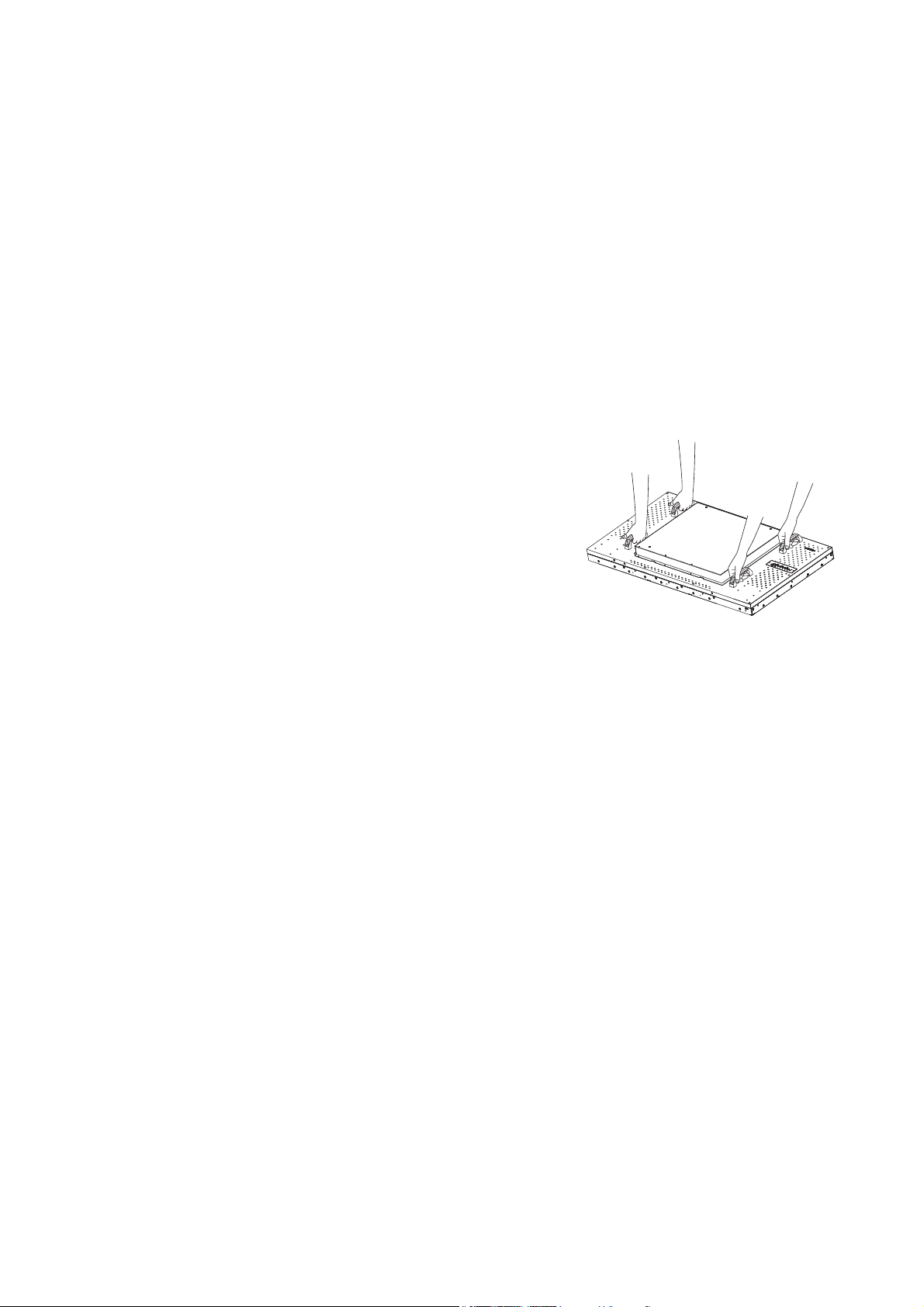
• Move a display by holding the handles on the back of the
display. Do not touch the LCD panel directly to avoid
possible scratches.
• To maintain proper ventilation and heat dissipation, keep at
least 60 mm of clear space from the mounted displays to
the wall.
• Ensure enough gap between displays to protect your LCD
screens from the damage through the direct transfer of
weight. See Checking the safe distance between displays on page 7 for details.
Notes on moving the display
The display has limited mechanical strength. To prevent the display from performance failure
caused by line defects, front bezel bending, glass scratch/broken, light leakage, etc, it must be
handled with care.
• Always move the display by at least two (2) adults.
• Keep the original shipping box and packaging in storage for use in the future when you may
need to transport the product.
• When you want to move the display, make sure the four (4) handles are held.
• When you want to place the display face down:
- Prepare a flat and horizontal surface that is larger than the display and spread a thick
protective sheet on it. (Fig. 1)
- Lay down the display gently and horizontally.
• When you want to upturn the display:
- Lift the display up horizontally by holding the four (4) handles. Do not lift the display
against its corner. (Fig. 2)
- Be careful not to scratch any parts of the display when upturning the display. (Fig. 3)
4 Video wall installation guide
Page 5
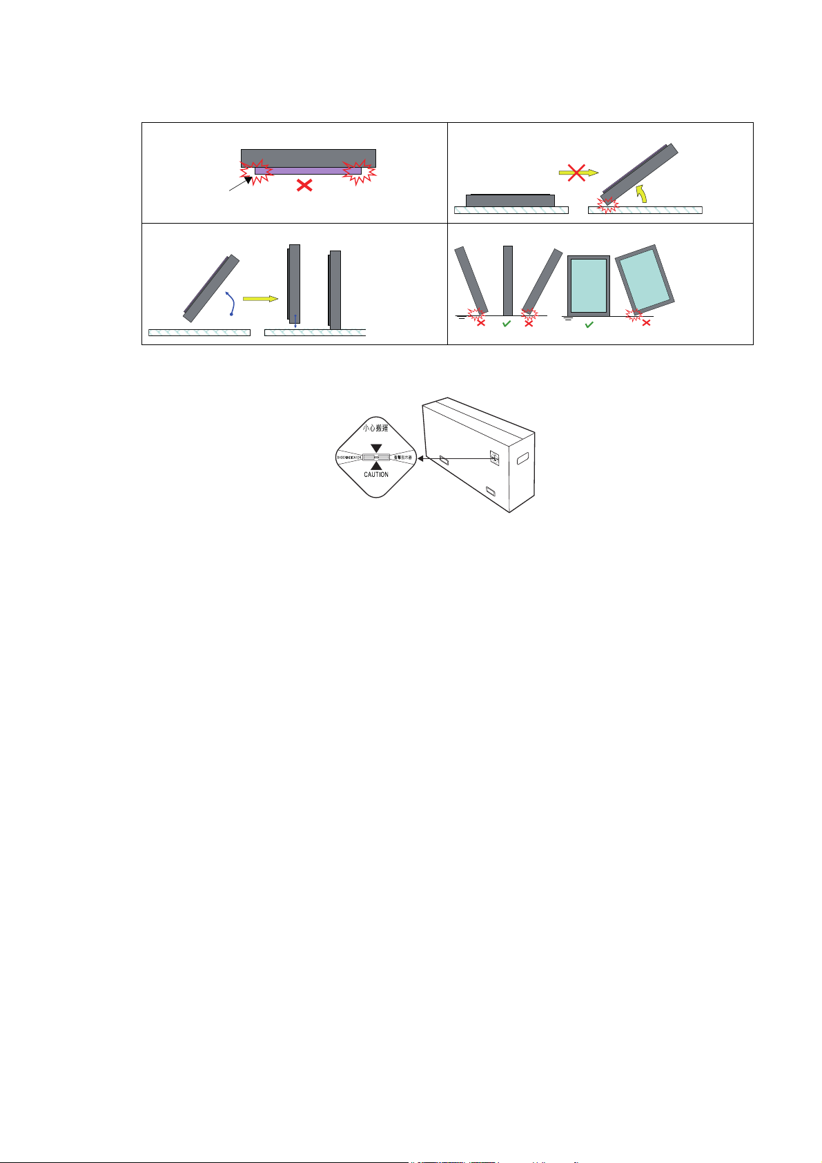
- Stand the display vertically to make sure the its weight spread evenly on the surface. (Fig.
Support surface
4)
(Fig.1) (Fig. 2)
(Fig. 3) (Fig. 4)
• Check the shock label on the outside of the product carton. The shock indicator on the label
will turn red if the display/package is improperly handled.
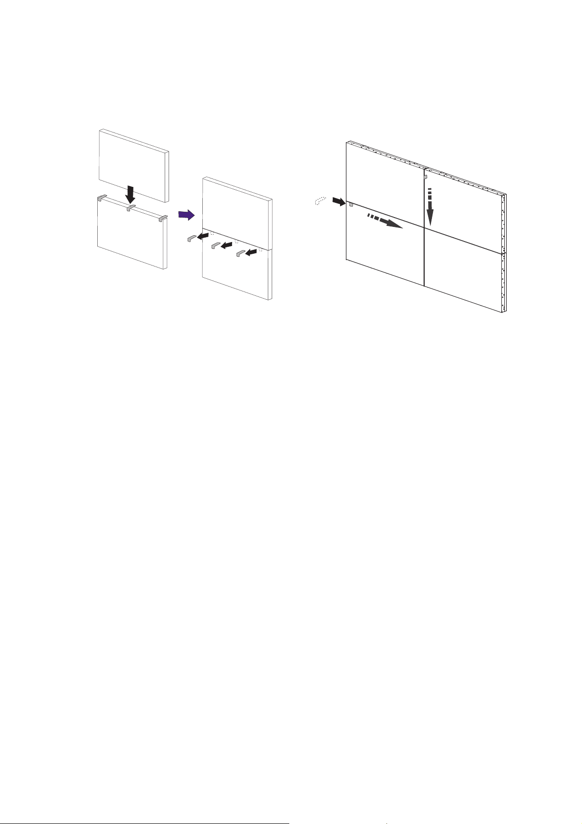
Installing
You can cascade the displays in landscape or portrait mode as desired. Mind the space between
displays during installation.
Cascading displays in landscape or portrait mode
1. Install the mounting bracket to the wall following the instruction manual of the wall
mounting bracket. Make sure the mounting bracket is vertically and horizontally placed.
2. Attach the provided gap inspection pads to the display edges as instructed in Step 1~3 in
Checking the safe distance between displays on page 7.
3. Mount and fasten the display on the mounting bracket or stand by tightening the screws
through the respective holes with a Phillips (cross) screwdriver. Do not place one display
directly on another as the stacked LCD screens may be damaged by the weight.
5 Video wall installation guide
Page 6
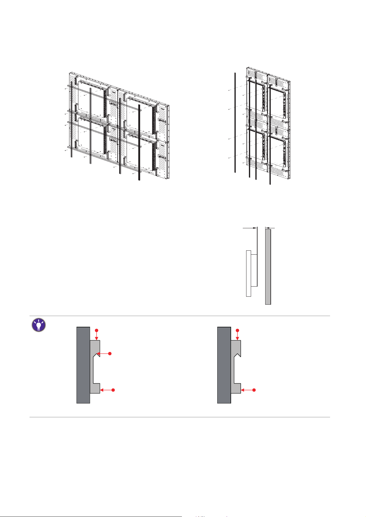
4. Start your video wall from the bottom left or bottom right. Finish one row and then
Landscape mode Portrait mode
For height adjustment
For tilt adjustment 1
For tilt adjustment 2
For height adjustment
For tilt adjustment
(Recommended)
(Not recommended)
move up to finish the next row. Once a display has been installed, check the horizontal
and vertical level immediately using a professional measuring tool.
5. Place your displays as close to each other
as possible but an appropriate space of at
least 0.5 mm should be kept. Check the
gap between displays as instructed in Step
4~5 in Checking the safe distance between
6. To maintain proper ventilation and heat
dissipation, keep at least 60 mm of clear
space from the mounted displays to the
wall.
60mm
(1.52")
displays on page 7.
Various mounting brackets may be available to you, but only some of them are suitable for a video wall.
6 Video wall installation guide
Page 7
Checking the safe distance between displays
Adhesive tape with peeling sheet
Front panel
During video wall installation, you might want to place the displays as close to each other as
possible. Note the LCD screens may be damaged through the direct transfer of weight if an
appropriate distance is not kept between displays. The recommended gap between displays may
vary depending on your purchased models as listed below.
Model name Recommended gap between displays
PH460 ≥ 0.5 mm
PL460 ≥ 0.5 mm
PH550 ≥ 0.5 mm
Actual bezel-to-bezel dimensions may exceed the listed minimum values (5.4mm for
PH460/PL460 and 5.3mm for PH550) due to different tiling methods.
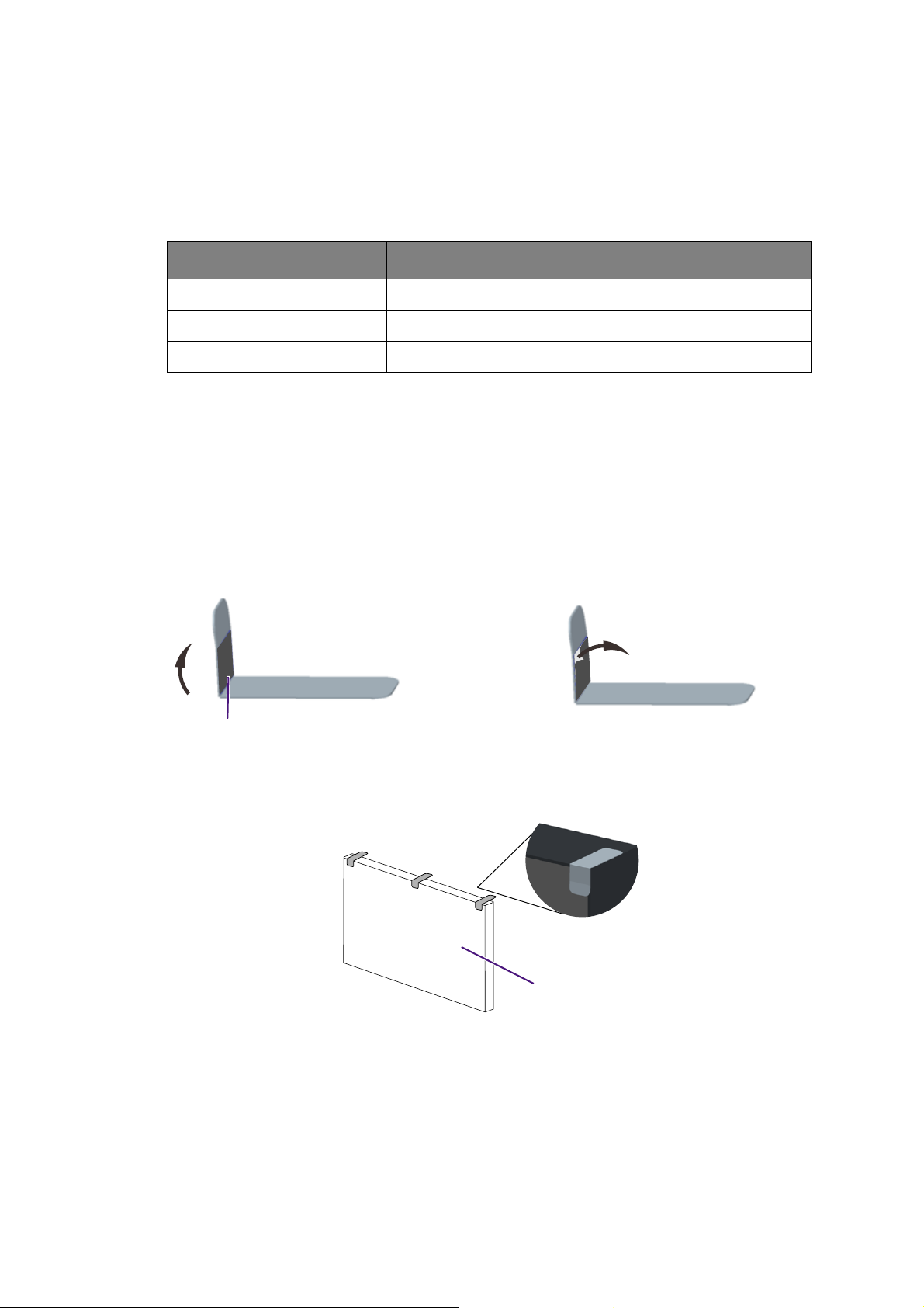
You are provided with gap inspection pads to ensure appropriate space between the cascaded
displays during video wall installation.
1. Get one of the provided gap inspection
pads and fold it as illustrated.
2. Remove the peeling sheet from the gap
inspection pad.
3. Stick the pad to the edge where another display will be stacked as illustrated. Each edge
should have 3 gap inspection pads attached.
7 Video wall installation guide
Page 8
4. After the displays are mounted and
fastened, check if the space between each
display is just enough for removing the gap
inspection pad smoothly. If the pad is
trapped, adjust the screws to release
more space.
5. Insert the pad again and swipe the pad
horizontally and vertically between the gap
to ensure it can move smoothly. Ignore
the black tapes on the edge if they stop
you. Refer to Recommended gap between
displays on page 7 for the minimum
distance required for each model.
8 Video wall installation guide
Page 9
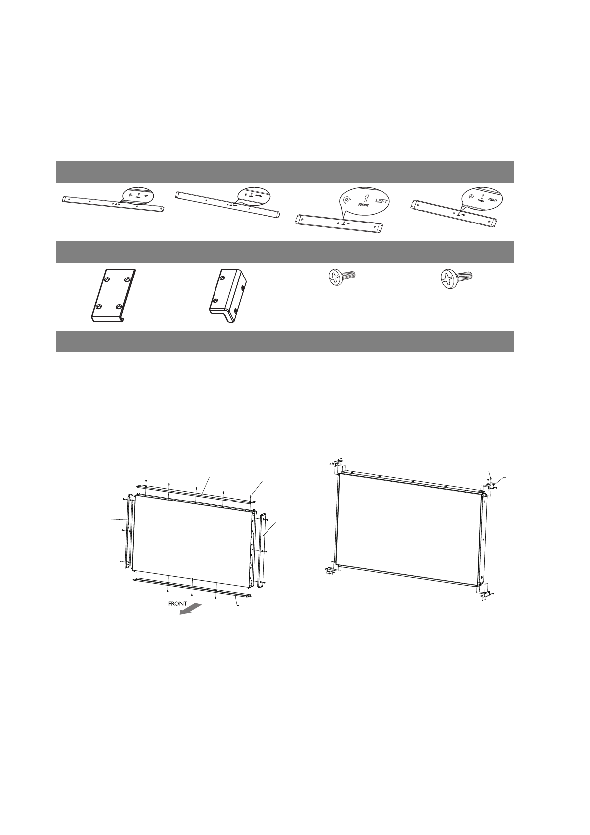
Installing edge finishing kit (optional)
A
H
D
B
C
Whether used as a standalone unit or as a part of a video wall, the edge finishing kit will
transform your display into a most stylish and elegant display.
Inside your edge finishing kit you will find the following components:
Cosmetic Plates
Top (A) Bottom (B) Left (C) Right (D)
Flat Enclosure (E) Corner Enclosure (F) M3 x 5 mm Screw (G) M4 x 6 mm Screw (H)
Installation
For standalone unit
1. Mount the cosmetic plates in their
respective places on the edge of your
display, and screw in to place using the 6
mm M4 screws.
2. On each corner, mount a corner enclosure
piece and fasten each one with 4 of the 5
mm M3 screws.
G
F
9 Installing edge finishing kit (optional)
Page 10
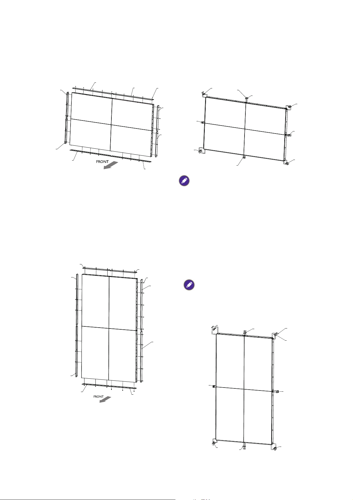
For a landscape video wall
A
A
H
D
D
B
B
C
C
F
E
G
F
E
F
E
F
E
C
H
A
A
D
D
B
B
C
F
E
F
E
F
E
F
E
G
1. Mount the cosmetic plates in their
respective places on the edge of your
display, and screw in to place using the
6mm M4 screws.
For a portrait video wall
2. On each corner, mount a corner enclosure
piece and fasten each one with 4 of the
5mm M3 screws. Where the displays meet,
use a flat enclosure piece, and fasten each
of these too with 4 of the 5mm M3 screws.
When mounting, make sure that all edge enclosure
pieces are fitted to the respective positions (i.e.
bottom to bottom, etc.)
1. Mount the cosmetic plates in their respective places on the edge of your display, and
screw in to place using the 6mm M4
screws.
2. On each corner, mount a corner
enclosure piece and fasten each one with
4 of the 5mm M3 screws. Where the
displays meet, use a flat enclosure piece,
and fasten each of these too with 4 of the
5mm M3 screws.
When mounting, make sure that all edge
enclosure pieces are fitted to the respective
positions (i.e. bottom to bottom, etc). When
rotating, the RIGHT side of the displays should be
on the bottom.
10 Installing edge finishing kit (optional)
Page 11

Cable extension guide
This guide provides additional information about how to extend VGA, HDMI and USB
connections as required in the environment where you set up your BenQ digital signage and
interactive flat panel displays. Refer to the instructions in this guide and the User Manual of
your BenQ display to ensure stable and optimal performance.
Pay attention to the following notes when you connect cables:
• Turn off all devices before making connections.
• Use certified, high-quality cables and signal amplifiers/repeaters.
• Familiarize yourself with the ports and sockets on the display and the devices you want to
connect. Be aware that incorrect connections may adversely affect picture quality.
• Do not remove cables from the ports and sockets by pulling the cable itself. Always grasp and
pull the connectors at the end of the cable.
• Ensure that all cables are fully inserted and firmly seated for proper pin contact.
11 Cable extension guide
Page 12

Extending the VGA connection using a VGA amplifier/repeater
D-Sub (15-pin)
cable
Audio cable
Computer
D-Sub (15-pin)
cable
VGA signal
amplifier/repeater
Display
Audio input jackVGA input
jack
If you need to connect the display to a computer or other VGA source devices over a long
distance (over 3 meters), a VGA signal amplifier must be used to boost the signal and prevent
potential display quality problems like interference and ghosting.
1. Connect the VGA input jack on the display to the VGA output jack on the VGA signal
amplifier/repeater using a D-Sub (15-pin) cable.
2. Connect the VGA output jack on the computer to the VGA input jack on the VGA signal
amplifier/repeater using a D-Sub (15-pin) cable.
3. Connect the computer’s audio output jack to the audio input jack on the display using a
suitable audio cable.
• Refer to the User Manual of your display for the location of VGA and corresponding audio input jacks.
• The audio cable, VGA signal amplifier/repeater and additional VGA cable are not supplied and should be
purchased separately.
12 Cable extension guide
Page 13

Extending the HDMI connection using an HDMI amplifier/
HDMI cable
HDMI cable
DVD/Blu-ray
HDMI signal
amplifier/repeater
HDMI input jack
Display
repeater
Although there is not an official limit on HDMI cable length (as it mainly depends on the quality
of the HDMI cable), in order to prevent potential display quality problems like interference and
ghosting, if you need to connect the display to a computer or an A/V device (such as a DVD or
Blu-ray player) over 5 meters, deployment of an HDMI signal amplifier is highly recommended.
1. Connect the HDMI input jack on the display to the HDMI output jack on the HDMI signal
amplifier/repeater.
2. Connect the HDMI input jack on the HDMI signal amplifier/repeater to the HDMI output
jack on the HDMI source device using an HDMI cable.
• Refer to the User Manual of your display for the location of HDMI input jacks.
• The HDMI cables and HDMI signal amplifier/repeater are not supplied and should be purchased
separately.
13 Cable extension guide
Page 14

Connecting faceplate
Faceplate
USB cable
Computer
USB cable
Display
USB port
1. Connect the mini-B plug of the supplied USB cable to the USB Mini-B port on the display,
and the type-A plug of the cable to the USB port on the faceplate.
2. Connect the computer to the faceplate using a suitable USB cable.
• Refer to the User Manual of your display for the location of USB port.
• Any cable used in prior installations for other displays and projectors in the same location should not be
used for a new installation of the display.
• Use only a high-quality faceplate.
• The total cable length between the display, computer and faceplate should not exceed 5 meters. If you
need to extend the length of USB connection, refer to "Extending USB connection" on page 15.
14 Cable extension guide
Page 15

Extending USB connection
USB cable
Active USB
extension cable
Computer
Display
USB port
Extending USB connection using an active (powered) USB extension cable
You can use a commercially available active (powered) USB extension cable on the market to
extend the length of USB connection. The active USB extension cable helps boost the USB
signal as well as provides sufficient bus power for the connected USB device.
1. Connect the mini-B plug of the supplied USB cable to the USB Mini-B port on the display, and
the type-A plug of the cable to the USB type-A port on the active USB extension cable.
2. Connect the type-A plug of the active USB extension cable to the USB port of a computer.
• Refer to the User Manual of your display for the location of USB port.
• For best results, use only a certified active USB extension cable.
• The type of USB port and plug on the active USB extension cable may be different from the description
above. Use a USB cable that matches the USB jack on the display and the USB port on the extension
cable.
• The length of the USB cable used to connect the display to the USB extension cable should not exceed 5
meters.
15 Cable extension guide
Page 16

Extending USB connection using an active (powered) USB-CAT
USB cable
Category 5/5e/6
network cable
USB cable
USB-CAT converter
Computer
Display
USB port
converter
You can use a commercially available active (powered) USB-CAT converter (extender) on the
market to extend the length of USB connection over a Category 5/5e/6 network cable.
1. Connect the mini-B plug of the supplied USB cable to the USB Mini-B port on the display, and
the type-A plug of the cable to the USB type-A port on the active USB-CAT converter.
2. Connect a Category 5/5e/6 network cable to the RJ-45 LAN ports on the converter.
3. Connect the converter to a computer using a suitable USB cable.
• Refer to the User Manual of your display for the location of USB port.
• Refer to the documentation of the active USB-CAT5 converter for the maximum length of the Category
5/5e/6 network cable.
• The type of USB port and plug on the active USB-CAT converter may be different from the description
above. Use a USB cable that matches the USB jack on the display and the USB port on the active USBCAT converter.
• Keep the Category 5/5e/6 network cable away from power lines and cables to avoid electronic
interference.
16 Cable extension guide
Page 17

Extending USB connection using an active (powered) USB extension
USB cable
Active USB
extension cable
USB cable
Computer
Faceplate
Display
USB port
cable and a faceplate
Depending on the environment where you install the display, you can use an active (powered)
USB extension cable to extend USB connection from a faceplate.
1. Connect the mini-B plug of the supplied USB cable to the USB Mini-B port on the display, and
the type-A plug of the cable to the USB type-A port on the active USB extension cable.
2. Connect the type-A plug of the active USB extension cable to the USB port on the
faceplate.
3. Connect the computer to the faceplate using a suitable USB cable.
• Refer to the User Manual of your display for the location of USB port.
• For best results, use only a certified active USB extension cable and high-quality faceplate.
• The type of USB port and plug on the active USB extension cable may be different from the description
above. Use a USB cable that matches the USB jack on the display and the USB port on the extension
cable.
• The total length of the USB cables used to connect the display to the active USB extension cable and
computer to the faceplate should not exceed 5 meters.
17 Cable extension guide
Page 18

Extending USB connection using an active (powered) USB-CAT
USB cable
USB-CAT converter
USB cable
Category 5/5e/6
network cable
Computer
USB cable
Faceplate
Display
USB port
converter and a faceplate
Depending on the environment where you install the display, you can use an active (powered)
USB-CAT converter to extend USB connection from a faceplate.
1. Connect the mini-B plug of the supplied USB cable to the USB Mini-B port on the display,
and the type-A plug of the cable to the USB type-A port on the active USB-CAT converter.
2. Connect a Category 5/5e/6 network cable to the RJ-45 LAN port on the converter.
3. Connect the converter to the faceplate using a suitable USB cable.
4. Connect the computer to the faceplate using a suitable USB cable.
• Refer to the documentation of the active USB-CAT converter for the maximum length of the Category
5/5e/6 network cable.
• The type of USB port and plug on the active USB-CAT converter may be different from the description
above. Use a USB cable that matches the USB jack on the display and the USB port on the active USBCAT converter.
• Keep the Category 5/5e/6 network cable away from power lines and cables to avoid electronic
interference.
• The total length of the USB cables used to connect the display to the active USB-CAT converter,
converter to the faceplate and computer to the faceplate should not exceed 5 meters.
18 Cable extension guide
Page 19

Additional information
Tier 1 (root tier)
Tier 7
Tier 6
Tier 5
Tier 4
Tier 3
Tier 2
Function Function
Host
Root hub
Function FunctionFunction
Hub A
Hub A
Function Function
Hub A
Hub C
Hub A
Hub B
Function
Function Function
Hub A
Hub D
Function
Function Function
Hub A
Hub E
Function
Function Function
Hub A
Hub F
Function
Your LCD display provides USB 2.0 ports for connecting to various devices including
computers, flash drives and wireless LAN adapters. This section provides basic information
about the USB 2.0 interface and serves as a reference for the deployment of your USB
connections.
USB terminology
Te r m Description/explanation
Host,
Function
A USB network consists of one master and multiple slave devices in a
star topology as illustrated below:
The master device (referred to as the “Host”) is on top of all other
slave devices (called “Function”). A computer is the most common
USB host. Any device that has a USB host controller and related
hardware and software installed can also become a USB host. A USB
function can be a USB mouse, keyboard or storage device.
A maximum of 7 tiers (including the root tier) are allowed in a single
USB network. Note that a USB device that performs both as a hub and
a function occupies two tiers.
19 Cable extension guide
Page 20

Te r m Description/explanation
Upstream The direction of data transmission from a USB function to a host
or hub.
Downstream The direction of data transmission from a USB host or hub to a
function.
Hub A USB device that provides upstream connection (port) to a host
and downstream connections (ports) to multiple functions.
Root hub A USB host that also performs the functions of a hub.
Speed (low-
speed, full-speed
Three different speeds are currently defined in the USB 2.0
specification:
and high-speed)
• Low-speed: data transmission at 1.5Mbps
• Full-speed: data transmission at 12Mbps
• High-speed: data transmission at 480Mbps
The actual transmission speed is determined by the device with
the lower (or lowest) speed. For example, if a low-speed
(1.5Mbps) USB peripheral is connected to a high-speed
(480Mbps) USB host, the maximum transmission speed between
these devices will be 1.5Mbps, not 480Mbps.
Active (self-
powered) device
Passive (bus-
powered) device
A USB device that has it own power supply and can operate
without the power supplied by the USB host.
A USB device that does not have its own power supply and solely
relies on the power supplied by the USB host.
USB connectors and receptacles
USB connectors and receptacles are grouped into two types: Type-A and Type-B.
Ty p e - A
ConnectorRecepta
cle
Standard
Mini
Micro
Ty p e - B
ConnectorRecepta
cle
Standard
Mini
Micro
• Type-A receptacles are used as outputs from host
systems and hubs.
• Type-A plugs are always oriented towards the host
system and mate with Type-A receptacles.
• Type-B receptacles are used as inputs to hubs or
devices.
• Type-B plugs are always oriented towards a USB
hub or device and mate with Type-B receptacles.
20 Cable extension guide
Page 21

USB cable length
For each passive connection between a two USB devices, the maximum length is 5 meters. To
extend USB connection beyond this length limit, an active extension cable has to be used to
ensure stable signal transmission and reliable power supply.
Prohibited cable assemblies
Some cable assemblies are prohibited in the USB specifications and are not recommended as
they may not work in all instances. For example, passive extension cable assembly: a cable that
has a Type-A plug on one end and a Type-A receptacle on the other, or a Type-B plug on one
end and a Type-B receptacle on the other. This allows multiple cable segments to be connected
together, possibly exceeding the maximum permissible cable length.
21 Cable extension guide
Page 22

Troubleshooting
Audio cable
DVD player / VCR
Component
video cable
Audio cable
DVD player / VCR
AV cableS-Video cable
Connections
The input and output ports illustrated here are for your reference only. The availability and
layout of all ports may vary by model.
How to connect a DVD player to the display?
You can use either Component or S-Video for connection.
DVI-OUT
HDMI-2
DVI-IN
HDMI-1
VGAOUT
VGAIN
DVI-OUT
HDMI-2
DVI-IN
HDMI-1
VGAOUT
VGAIN
22 Troubleshooting
Page 23

How to connect a computer to the display?
D-Sub (15-pin) cable Audio cable
Computer
Analog signal
DVI-OUT
DVI-IN
HDMI-2
HDMI-1
VGAOUT
VGAIN
Audio cable
Computer
DVI-D cable
HDMI
cable
DisplayPort cable
Digital signal
You can connect a computer to the display through D-Sub (VGA) / DVI / HDMI / VGA as
desired.
DVI-OUT
HDMI-2
DVI-IN
HDMI-1
VGAOUT
VGAIN
23 Troubleshooting
Page 24

How to connect to external speakers?
External speakers
While the display is turned off, connect external speakers to the SPEAKERS (R/L) jacks on
the display via an appropriate audio cable. And then turn on the display.
DVI-OUT
HDMI-2
DVI-IN
HDMI-1
VGAOUT
VGAIN
24 Troubleshooting
Page 25

Picture / video
No picture is displayed.
Possible causes Possible solutions
The power cord is not connected. Re-connect the power cord.
The main power switch on the
back of the displayed is not
switched on.
The selected input is not
connected.
The display is in Standby mode
when the input source is D-Sub
(VGA).
Incorrect cable connection.
The main board could be
damaged.
Make sure the power switch is switched on.
Depending on the selected input, connect the display with
the input source using the appropriate cable(s).
Check the cable connection. See the user manual for
details.
Press any of the control panel (keypad) buttons and check
if the OSD menu could be displayed. If yes, the problem lies
somewhere else.
Try with another display resolution or another graphic card
(GPU).
Restore the display to the default factory settings.
Contact the BenQ authorized service partner for
replacement.
Screen interference is observed or noise is heard.
Possible causes Possible solutions
This could be caused by other
appliances, traffic, or fluorescent
lights in the surroundings.
Poor quality cable is used for
signal input.
The image has a faulty coloration.
Possible causes Possible solutions
The video cable is not connected
properly.
• Go to Picture > Noise Reduction.
• Move the display to another location to see if the
interference is reduced.
Try with another video cable.
Make sure the video cable is connected firmly to the
display.
25 Troubleshooting
Page 26

The picture is distorted with strange patterns.
Possible causes Possible solutions
The video cable is not connected
properly.
The image format is not
supported by your display.
Make sure the video cable is connected firmly to the
display.
Check the specifications to verify the display’s supported
formats.
The picture does not fill up the full screen when the input source is D-Sub (VGA).
Possible causes Possible solutions
Go to Screen > Aspect > Wide Zoom or Zoom to
adjust the display’s geometry and time frequency
The picture is not properly
zoomed.
parameters. Refer to the user manual for more
information on the menu options.
Note the picture may be distorted or stretched if fitted to
the screen.
You are running the display at its native resolution, but the image is still distorted.
Possible causes Possible solutions
Images from different input
sources may appear distorted or
stretched on the display running at
Go to Screen > Aspect to set a proper aspect ratio for
the input source.
its native resolution.
Sound can be heard but no image is displayed.
Possible causes Possible solutions
The video cable is not connected
properly.
Make sure the video cable is connected firmly to the
display.
(If the input is HDMI)
Try with another HDMI cable.
Poor cable quality.
26 Troubleshooting
Page 27

The picture unstable, unfocused, or swimming.
• Make sure the video cable is connected firmly to the display.
• Go to Screen > Adjust Screen to focus and adjust the display. Try with Auto
Adjustment first to adjust the settings automatically. If it does not help, you can make
adjustment manually. Once the display mode is changed, you may need to adjust the screen
again.
• Check if a supported timing is set. On your display, press INFO on the remote control to
find out the current resolution and timing. Alternatively, you can check the information from
your computer. The way to check the timing may differ by operating system. Refer to the
help document of your operating system for details.
• Try with another video cable.
Does my display support PIP (Picture in Picture) function?
Yes, but the availability of PIP function also depends on the video sources. Refer to
Supported PAP input signal combination in the user manual of the purchased model
for details.
The PIP function will be disabled if the video wall or the touch function is in use.
The picture is not displayed in the center of the screen when the input source is D-Sub (VGA).
Go to Screen > Adjust Screen to make adjustment.
For advanced setting, change the setting under H. Position and V. P os it i on . See the user
manual of the purchased model for more information.
In H. Position, press /+ on the control panel to move the picture to the right; press /- to
move the picture to the left.
In V. Po sit io n , press /+ on the control panel to move the picture up; press /- to move the
picture down.
What are the supported resolutions of my display?
The supported resolutions may differ by model. Refer to Supported input signal
resolution in the user manual of the purchased model for details.
What is the recommended refresh rate?
The recommended refresh rate for your display is 60 Hz.
27 Troubleshooting
Page 28

The display flickers when I launch or close a program.
• The signal may not be stable. Check the cable connection or try with another video cable.
• The panel backlight may be unstable. Contact the BenQ authorized service partner for
replacement.
Audio
The image is displayed but no sound is heard.
Possible causes Possible solutions
Your graphic card driver is not
installed or updated.
The audio cable is loose.
Not external speakers are
connected.
The audio output device is not
consistent with the display setting.
Either the display’s or PC’s
Speaker has been muted.
The main board could be
damaged.
(If the signal source is HDMI / DP)
The Speakers in your OS is not
set properly.
Your display’s audio input is not
set to DisplayPort or HDMI.
Update the driver through Windows Update (for
Windows Operating Systems) or the graphic card’s
manufacturer.
Power off the display and re-connect the audio cable.
Power on the display again.
Connect external speakers to the display and adjust the
volume appropriately.
Make sure the setting in Speaker on your display is the
same with the audio output device.
Disable mute by pressing the MUTE button on the remote
control.
Contact the BenQ authorized service partner for
replacement.
Set DisplayPort or HDMI as the default speaker in your
operating system and launch the media player again.
Set the Audio Source of your display to DisplayPort or
HDMI.
Remote control
The remote control does not work.
Possible causes Possible solutions
The battery drained out. Replace with a new battery.
The remote control is damaged. Try with a new remote control.
Check if the LED indicator of the IR receiver lights red or
The IR receiver could be damaged.
It is out of the IR remote control
range.
28 Troubleshooting
does not light up. If so, contact the BenQ authorized
service partner for replacement.
Check the specifications and adjust the distance between
the remote control and the display.
Page 29

Touch function (selected models only)
The touch function does not work.
Possible causes Possible solutions
The touch function is not
supported by your OS.
The touch driver is not installed.
No stable or enough power
supplied for your computer.
The touch sensor is covered by
dust.
Check the user manual for the supported operating
systems.
Visit the BenQ local website for the appropriate driver
files.
The touch module needs to get enough power supply from
your computer to work well.
• Try with another computer.
• Disconnect all the other USB peripherals.
• Add a power hub that helps supply more power to your
computer.
Clean the touch sensor properly.
1. Be sure to turn off the display and unplug the power
cord before you clean the screen.
2. Remove dust or dirt from the screen and the infrared
plastic filter periodically. It is suggested using a small
amount of alcohol to clean the infrared plastic filter.
3. Moisten a clean, soft, lint-free cloth with a neutral
detergent and then clean the touch screen.
Use a neutral detergent to clean the touch screen. Avoid using
detergents with erosive substance, such as banana oil or
ammonia. To avoid damage to the screen, never use any type of
abrasive materials to wipe the screen.
• Check if the USB cable has been connected properly, or
try with another USB cable.
• Connect the computer with your display only; remove
Poor USB connection.
other USB peripherals.
• Connect a computer with the display through USB cable
directly without any extension (e.g. faceplate or USB
extension cable) to ensure the touch function works.
The drawing is not displayed correctly (e.g., double lines, spiking, etc.).
Possible causes Possible solutions
An inappropriate stylus
(particularly too thin) is used.
Try with a thicker stylus. Refer to the following stylus
specifications.
29 Troubleshooting
Page 30

Performance Stylus dimensions Accuracy Applicable models
NextWindow < 47" diameter: Ø6,
± 3mm ≤ 55"
T420 / T650 / TL550 /
TL650 / RP650 / RP650+
65": Ø9
5mm > 55"
Nexio 42" / 45" / 55": Ø8 ± 2.5mm IL420 / IL460
IRTouch 65" diameter: Ø8 ± 1.5mm in center,
IL650 / RM650
± 2.5mm near
border
Strong light reflection.
The interactive software
(purchased and installed separately
by user) may not be compatible
Re-direct the lights or move the display to another location
to avoid unwanted reflections from light sources.
• Try with a different version of interactive software.
• Try with the basic drawing program pre-installed on your
computer. (e.g. Microsoft Paint in Windows).
with the system.
Poor USB connection.
Check if the USB cable has been connected properly, or
try with another USB cable.
OSD menu / control panel / power button
The OSD menu does not work.
Possible causes Possible solutions
• To lock/unlock both the control panel and remote
control buttons, press for 5 seconds, and then ENTER
on the remote control.
The control panel (keypad) and/or
remote control buttons are
locked.
• To lock/unlock the control panel buttons, press and hold
/- and /+ on the control panel simultaneously for 5
seconds.
• To lock/unlock the remote control functions, press and
hold MENU and /- on the control panel for 5 seconds.
The control panel (keypad) could
be damaged.
Contact the BenQ authorized service partner for
replacement.
Some of the OSD menu options are grayed out. When are those items available for setup?
Available menu options may vary depending on the input sources, functions and settings.
30 Troubleshooting
Page 31

The power button does not respond.
Possible causes Possible solutions
Power cord is not connected
properly.
The control panel could be
damaged.
Re-connect the power cord.
Contact the BenQ authorized service partner for
replacement.
LED indicators
The LED indicator of control panel (keypad) or IR receiver flashes red quickly.
Possible causes Possible solutions
The main board could be
damaged.
Contact the BenQ authorized service partner for
replacement.
Power
The display can’t be powered on.
Possible causes Possible solutions
No power is supplied to the
display.
One of the key components of the
display could be damaged.
• Re-connect the power cord.
• Check if the power outlet works.
Contact the BenQ authorized service partner for
replacement.
31 Troubleshooting
Page 32

System
How to restore the factory default settings?
Go to Setting > All Reset. All except the settings under the Picture and Sound menus
will be restored back to the factory default settings.
To reset all settings in Picture, go to Picture > Reset.
To reset all settings in Sound, go to Sound > Reset.
How to set time and date?
Go to Setting > Schedule.
Press the control panel buttons to adjust the system clock. Refer to the user manual for more
information.
What to do if the Out of Range message is prompted?
The resolution currently set is not supported. Refer to Supported input signal
resolution in the user manual of the purchased model for the supported timings.
What are the supported resolutions of my display?
The supported resolutions may differ by model. Refer to Supported input signal
resolution in the user manual of the purchased model for details.
Vapor or mist is observed inside the glass.
Under certain circumstances, condensation may occur on the inner side of the cover glass, it's
a natural phenomenon and will not affect the operation of the display. This condensation will
usually disappear after around 2 hours of normal operation.
How to check the version of system software?
Go to Setting > Information > Software Version to find out the software version.
32 Troubleshooting
Page 33

Wall mounting / video wall
Is wall mounting kit available?
The wall mounting kit should be purchased separately, though the screws needed for wall
mounting are included in the product.
The mounting interface should comply with the UL1678 standard in North America. The mounting means
should be strong enough to bear the weight of the display.
What to do if colors among all displays do not match?
Re-connect a cable from one computer to another to check if it is the video output that went
wrong.
Re-connect a cable from one display to another to check if it is the display that went wrong.
If it is the video input that went wrong, check the following:
• Make sure that the signal is output from the same source (e.g. D-Sub).
• It is recommended to use cables of equal length for connection.
• Do not use more than 2 splitters to produce video wall.
• If the total fitment width of the video wall is more than 10 meters, use an amplifier or
resistance wire avoid signal attenuation during transmission.
• If the signal came from more than one computer, make sure that all computers use the same
type of graphic card.
If it is the display that went wrong, check the following:
• Check if all the settings of the following options in the Picture menu on all displays are
identical.
- Picture Mode (Standard mode is recommended)
- Backlight
- Contrast
- Brightness
- Chroma
- Phase
- Sharpness
- Color Temp.
• Check if the settings of Adaptive Contrast and Ambient Light Sensor in Setting >
Advanced on all displays are identical.
• Adjust the colors by calibration tools (purchased separately).
I, _____________________ hereby confirm that I have read this document and understand
its content.
2014/1/7
33 Troubleshooting
 Loading...