

Release 1.0
Technical Documentation
10/2005
TD_Repair_L2.5L_AF51_R1.0.pdf Page 1 of 56
Service Manual
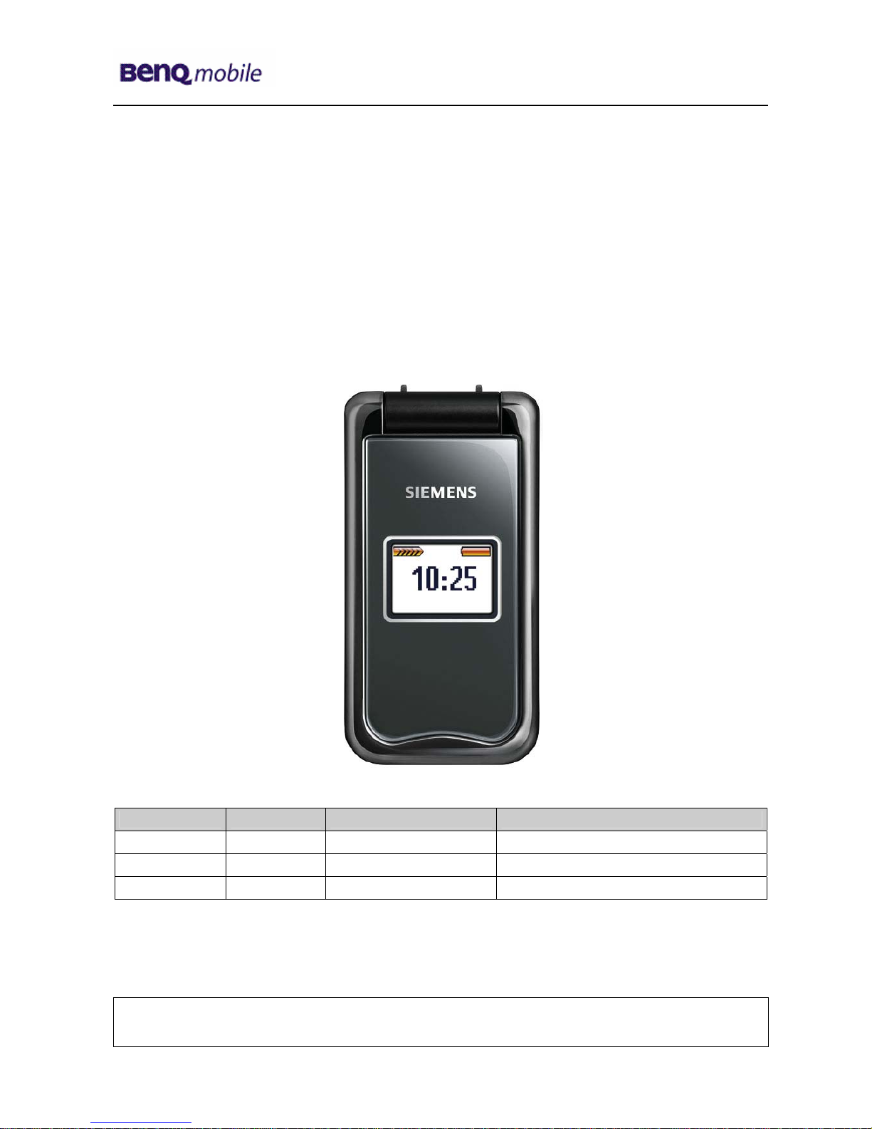
AF51
Level 1-3
Release Date Department Notes to change
R 1.0 29.12.2005 BenQ Mobile S CC CES New document
Company Confidential
2005©BenQ
Release 1.0
Technical Documentation
10/2005
TD_Repair_L2.5L_AF51_R1.0.pdf Page 2 of 56
Table of Content
1 Key Feature................................................................................................................................3
2 AF51 Interface to Accessories................................................................................................. 4
3 Unit Description of AF51...........................................................................................................4
4 Exploded View of AF51.............................................................................................................5
5 Disassembly of AF51................................................................................................................6
6 Assembly of AF51...................................................................................................................17
7 BenQ Service Equipment User Manual.................................................................................27
8 GRT Software: Functionality Configuration..........................................................................28
9 GRT Software: Regular Usage ...............................................................................................30
10 JPICS (Java based Product Information Controlling System)............................................35
11 International Mobile Equipment Identity, IMEI......................................................................41
12 General Testing Information...................................................................................................42
13 Introduction of Service Repair Documentation for Level 3 Basic Repairs – AF51 ...........48
14 List of available Level 3 Basic Parts......................................................................................49
15 Hardware Requirements.........................................................................................................49
16 AF51 Board Layout .................................................................................................................50
17 SIM Card Problems .................................................................................................................51
18 IO Connector Problems ..........................................................................................................52
19 B to B Connector (upper slider part) Problems....................................................................53
20 Main Keypad Illumination Problems......................................................................................54
21 Connector Battery...................................................................................................................55
22 Filter EMI Problems.................................................................................................................56
Company Confidential
2005©BenQ
Release 1.0
Technical Documentation
10/2005
TD_Repair_L2.5L_AF51_R1.0.pdf Page 3 of 56
1 Key Feature
Battery
Li-Ion 620 mAh
Stand – by Time
Up to 220 hrs (standard battery)
Talk Time
Up to 300 min (standard battery)
SIM Functionality /
Security Controls
SIM lock
Secure transactions
Digital signatures
Digital Rights Management: OMA standard
Data Services
SMS, SMS MT, SMS MO
MMS rel. 4
GPRS class 8
WAP 1.2.1, WAP 2.0 content provisioning
Java MIDP 1.0, CDLC 1.0
WML/XHTML dual stack
System Standards
Tri-band: 900/1800/1900 MHz
(for EMEA, APAC and LAM)
EGSM (GSM phase 2/phase 2+)
Antenna
Integrated
Length
79 mm
Width
41 mm
Weight
80g
Display
Main-Display: CSTN, 130 x 130 pixels, 65,536 colors
Sub-display: CSTN, 96 x 64 pixels, 65,536 colors
Features
4-way navigation key and two soft keys
Two color displays: 65,536 color internal glass display, 65,536 color
external display
SMS to group, predefined text blocks
MMS supporting text, still images, voice and animations
32-chord polyphonic ring tones, MIDI, SP MIDI, WAV
Speed dialing keys
Programmable soft keys
Incite Service Light Indication LED
Calendar including day, week, and month
PC-Synchronization with Mobile Phone Manager
Personal information manager
GPRS modem assistant
J2ME (Java) based games and applications
Handsfree talking
Silent alert (Vibra)
Games, Speaker-dependent voice dialing
File manager: Flash File System and Explorer
Calculator, Currency converter
Birthday reminder
Start-up assistant for clock set
Car Kit Portable as accessory
Company Confidential
2005©BenQ
Release 1.0
Technical Documentation
10/2005
TD_Repair_L2.5L_AF51_R1.0.pdf Page 4 of 56
2 AF51 Interface to Accessories
Nano I/O connector is for G85 generation. The compatible interface is suitable to use the travel
charger.
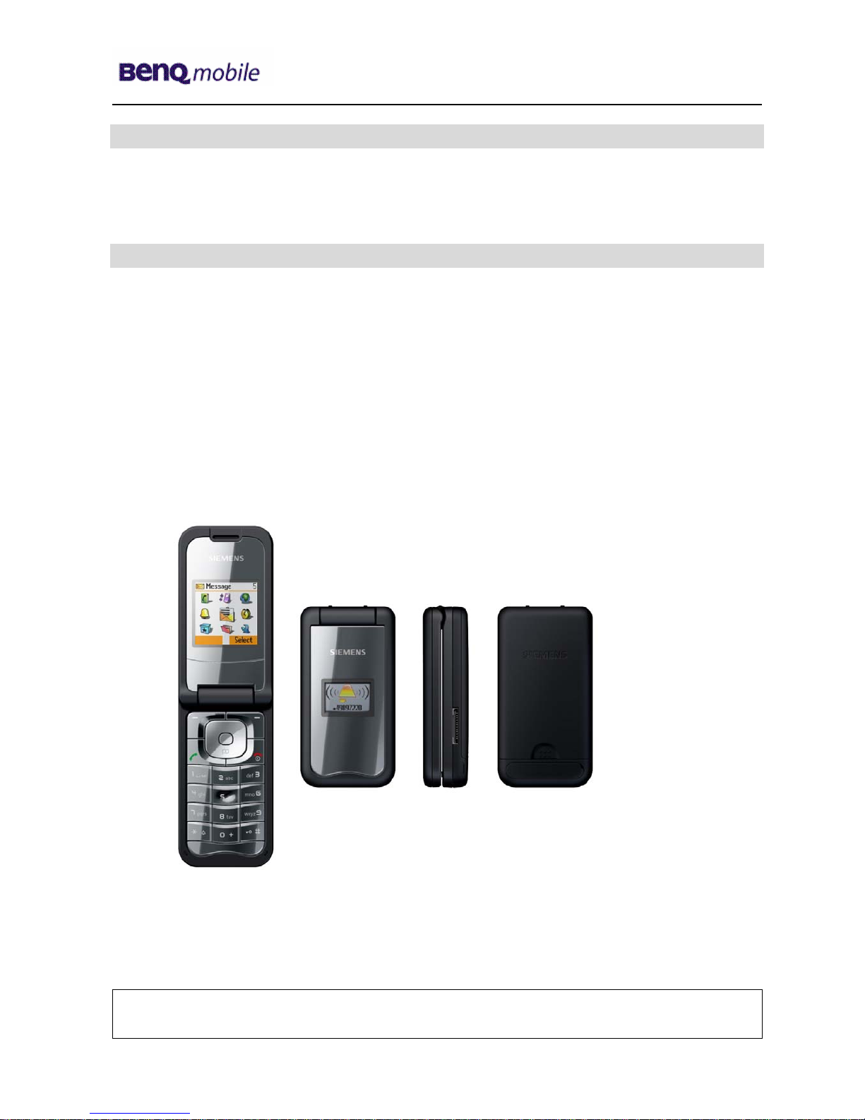
3 Unit Description of AF51
Demonstrate modern styling with the timelessly elegant “pocket size” clamshell design with
integrated antenna and a valuable look.
The highly scratch-resistant internal glass display surface preserves the visibility of the colors
displayed and ensures a long-lasting, enjoyable user experience.
Ergonomic keypad and two color displays for convenient, easy handling. The integrated organizer
supports the simplification of daily life. The Incite Service Light Indication LED informs the user at a
glance about missed calls and incoming SMS, etc., under any light conditions.
Company Confidential
2005©BenQ
Release 1.0
Technical Documentation
10/2005
TD_Repair_L2.5L_AF51_R1.0.pdf Page 5 of 56
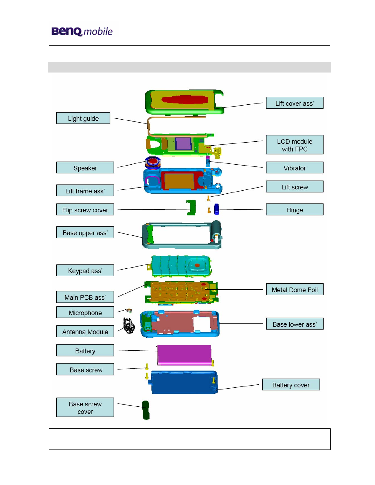
4 Exploded View of AF51
Company Confidential
2005©BenQ
Release 1.0
Technical Documentation
10/2005
TD_Repair_L2.5L_AF51_R1.0.pdf Page 6 of 56
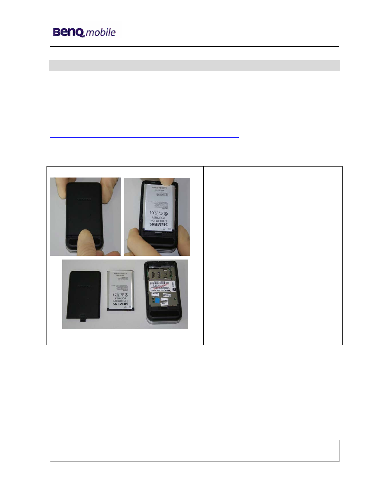
5 Disassembly of AF51
All repairs as well as disassembling and assembling have to be carried out in an ESD
protected environment and with ESD protected equipment/tools. For all activities the
international ESD regulations have to be considered.
For more details please check information in c – market
https://market.benqmobile.com/SO/welcome.lookup.asp
There you can find the document “ESD Guideline”.
Step 1
Remove Battery Cover and Battery.
Company Confidential
2005©BenQ
Release 1.0
Technical Documentation
10/2005
TD_Repair_L2.5L_AF51_R1.0.pdf Page 7 of 56
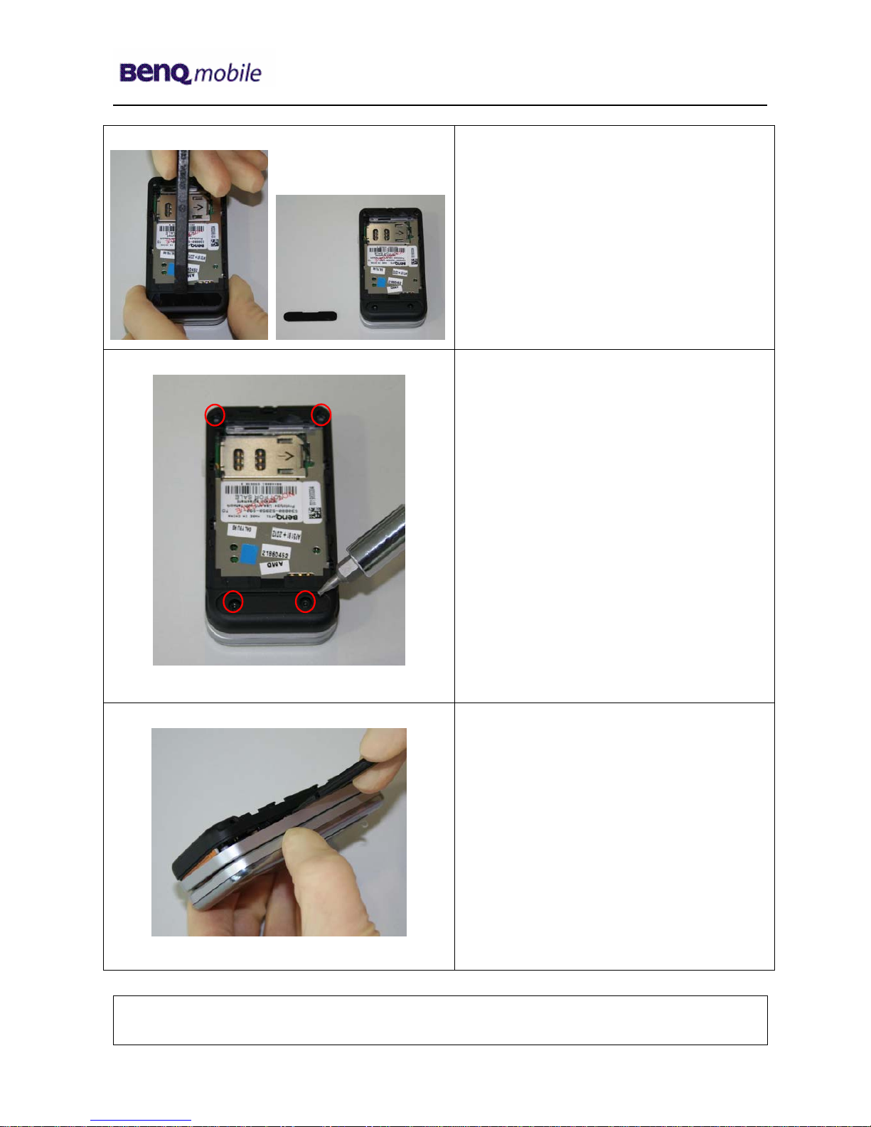
Step 2
Remove Screw cover with the alternative
opening tool
Step 3
Remove screws with the Torque –
Screwdriver T5+
Step 4
Remove rear cover with the Alternative
Opening Tool carefully.
Company Confidential
2005©BenQ
Release 1.0
Technical Documentation
10/2005
TD_Repair_L2.5L_AF51_R1.0.pdf Page 8 of 56
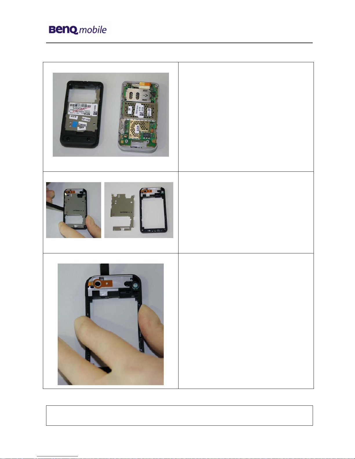
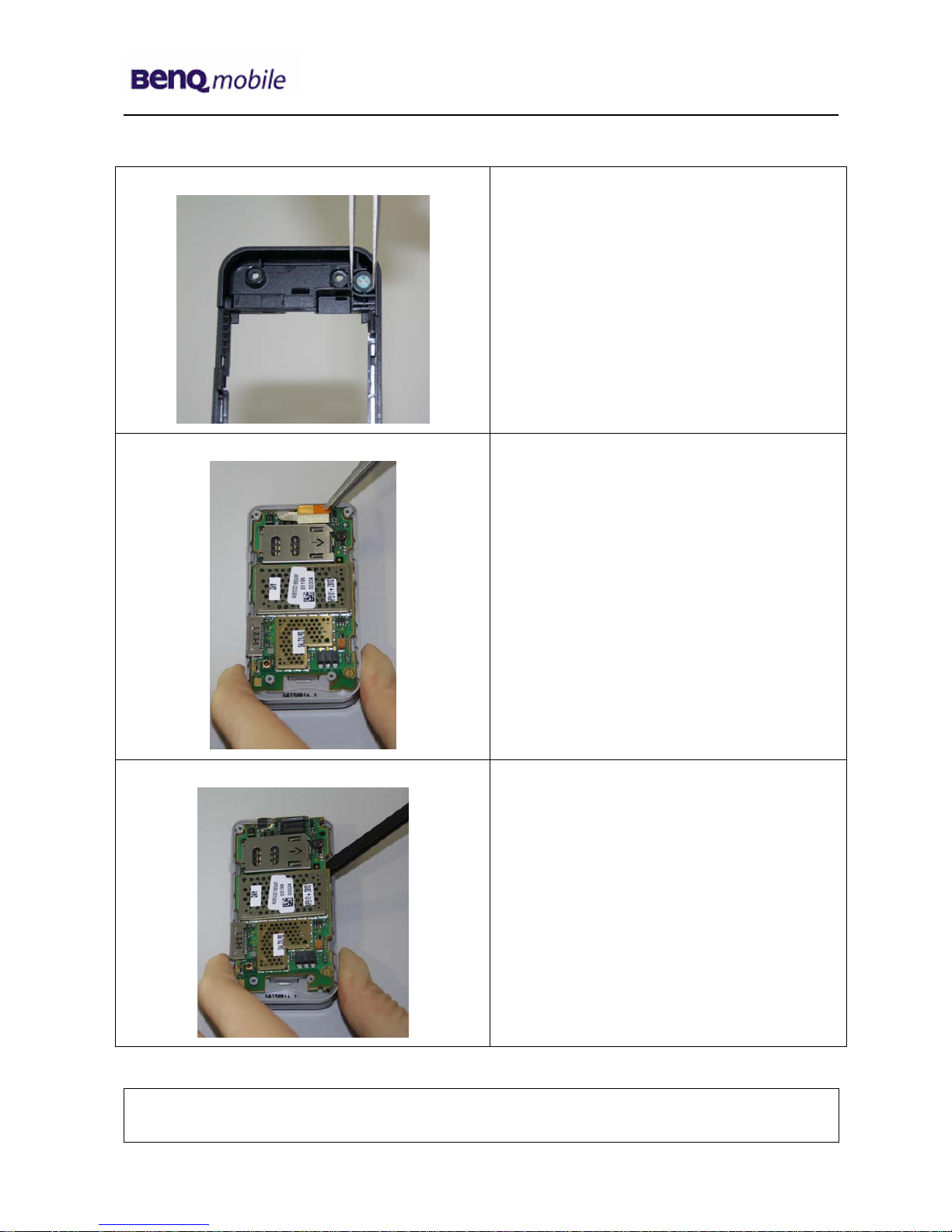
Step 5
Step 6
Remove PCB cover plate by using the
alternative opening tool.
Step 7
Remove antenna by using the alternative
opening tool.
Company Confidential
2005©BenQ
Release 1.0
Technical Documentation
10/2005
TD_Repair_L2.5L_AF51_R1.0.pdf Page 9 of 56
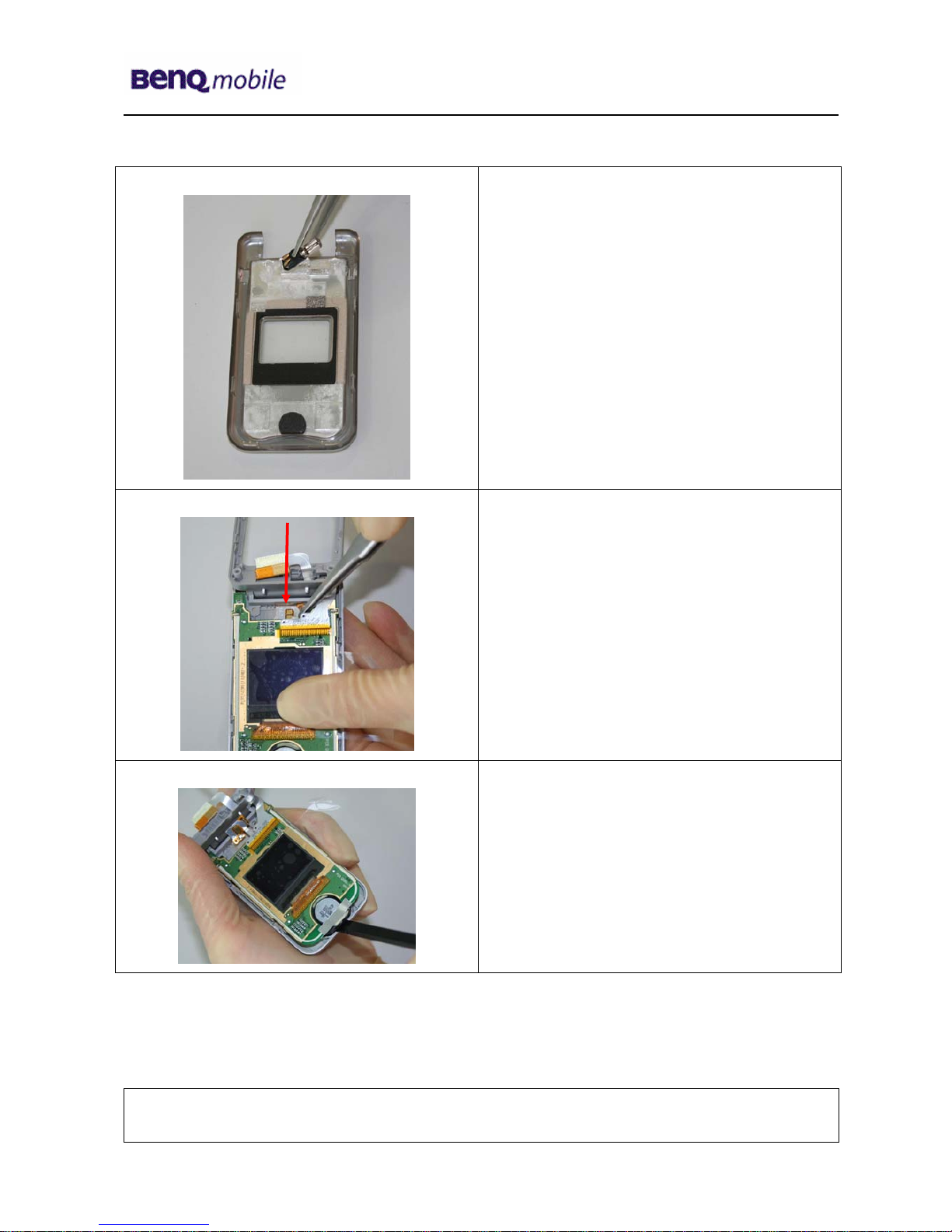
Step 8
Remove microphone by using tweezers
carefully.
Step 9
Disconnect the Flex Cable from PCB by
using Tweezers.
Step 10
Assemble PCB by using the tweezers
carefully.
Company Confidential
2005©BenQ
Release 1.0
Technical Documentation
10/2005
TD_Repair_L2.5L_AF51_R1.0.pdf Page 10 of 56
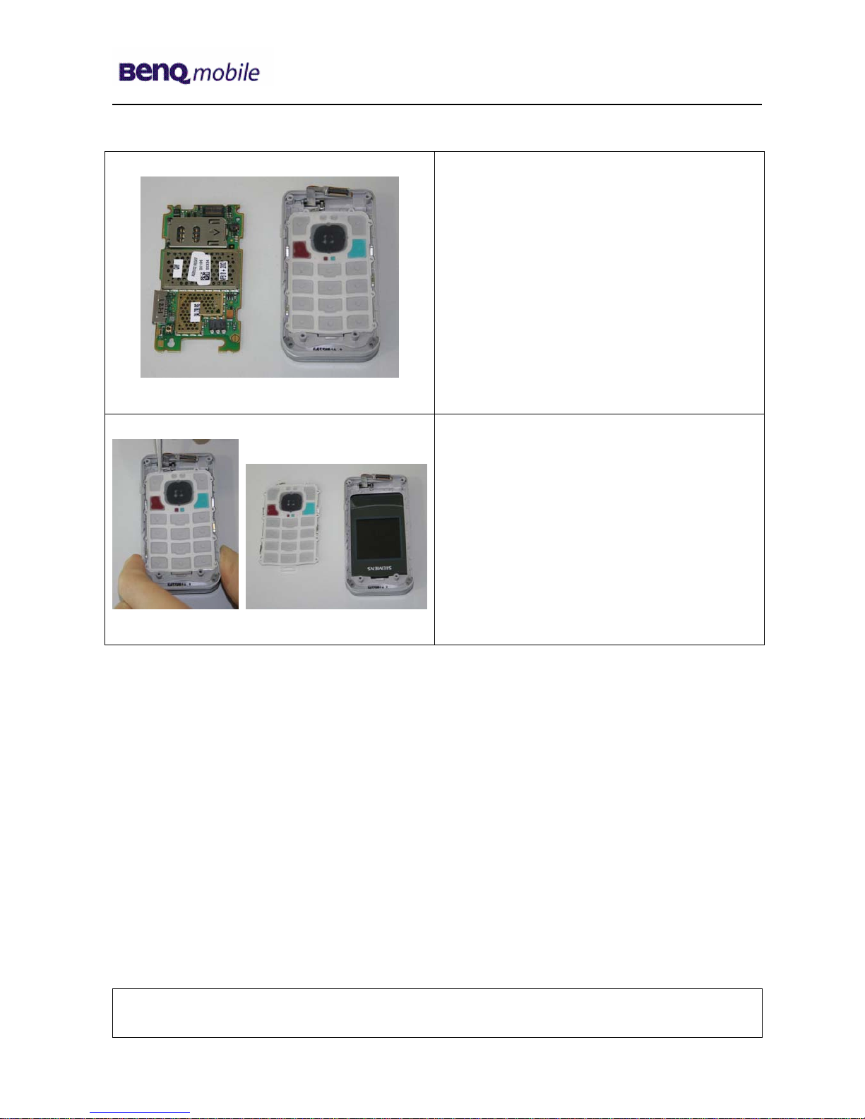
Step 11
Step 12
Remove Keypad by using Tweezers.
Company Confidential
2005©BenQ
Release 1.0
Technical Documentation
10/2005
TD_Repair_L2.5L_AF51_R1.0.pdf Page 11 of 56
Step 13
Remove screw cover by using the
alternative opening tool carefully.
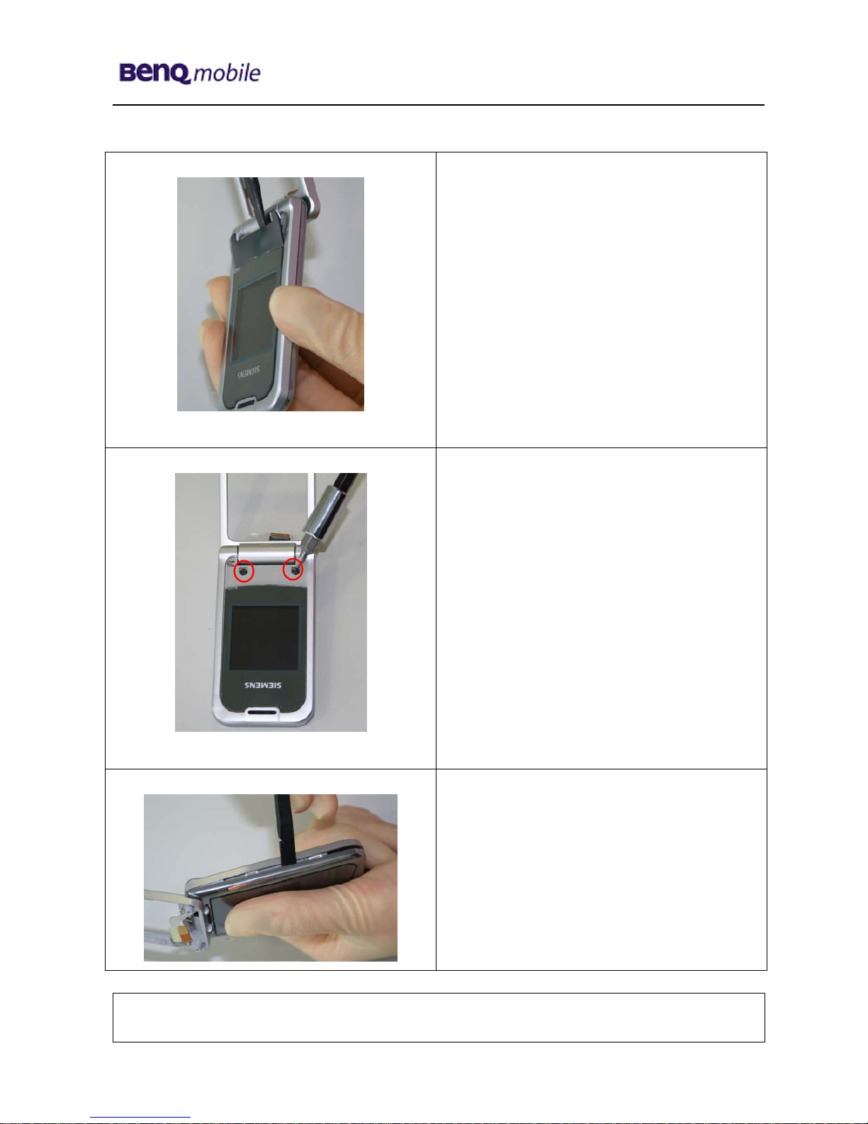
Step 14
Remove screws with the Torque –
Screwdriver T5+
Step 15
Remove Front Cover with the Alternative
Opening Tool.
Company Confidential
2005©BenQ
Release 1.0
Technical Documentation
10/2005
TD_Repair_L2.5L_AF51_R1.0.pdf Page 12 of 56
Step 16
Step 17
To avoid scratches it is mandatory to place
a protection foil onto the Display!!!
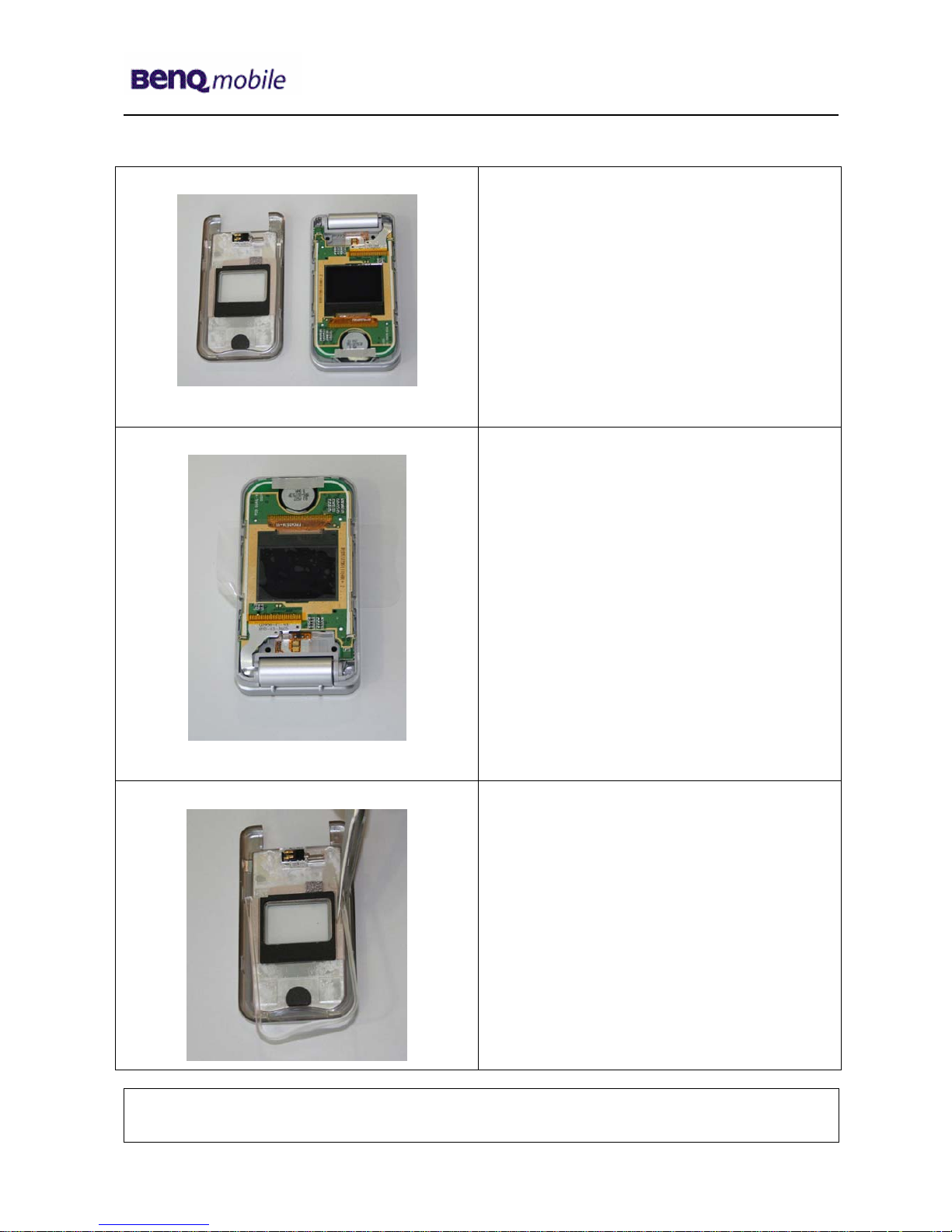
Step 18
Remove Display spacer.
Company Confidential
2005©BenQ
Release 1.0
Technical Documentation
10/2005
TD_Repair_L2.5L_AF51_R1.0.pdf Page 13 of 56
Step 19
Remove Vibramotor by using tweezers.
Step 20
Remove Vibra contact Flex foil by using
tweezers carefully
Step 21
Remove PCB by using the alternative
opening tool. Separate Earphone from front
cover carefully.
Company Confidential
2005©BenQ
Release 1.0
Technical Documentation
10/2005
TD_Repair_L2.5L_AF51_R1.0.pdf Page 14 of 56
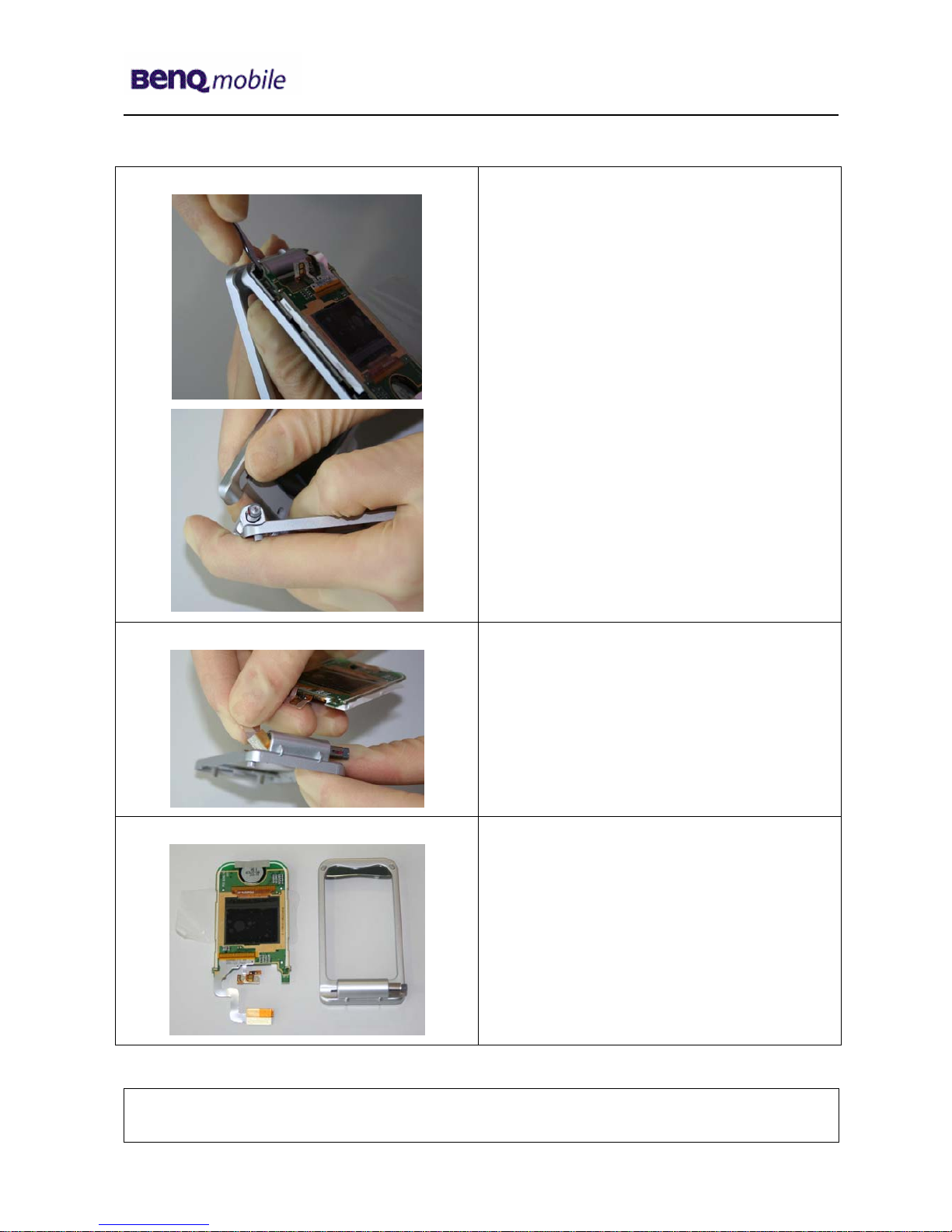
Step 22
Remove Upper Case from Lower Case by
pushing the Hinge-spring, now you can
separate the Upper Base Frame from the
Lift Frame.
Take care of the Flex Cable!!!
Step 23
Remove PCB from Lower base frame.
Take care of the Flex Cable!!!
Step 24
Company Confidential
2005©BenQ
Release 1.0
Technical Documentation
10/2005
TD_Repair_L2.5L_AF51_R1.0.pdf Page 15 of 56
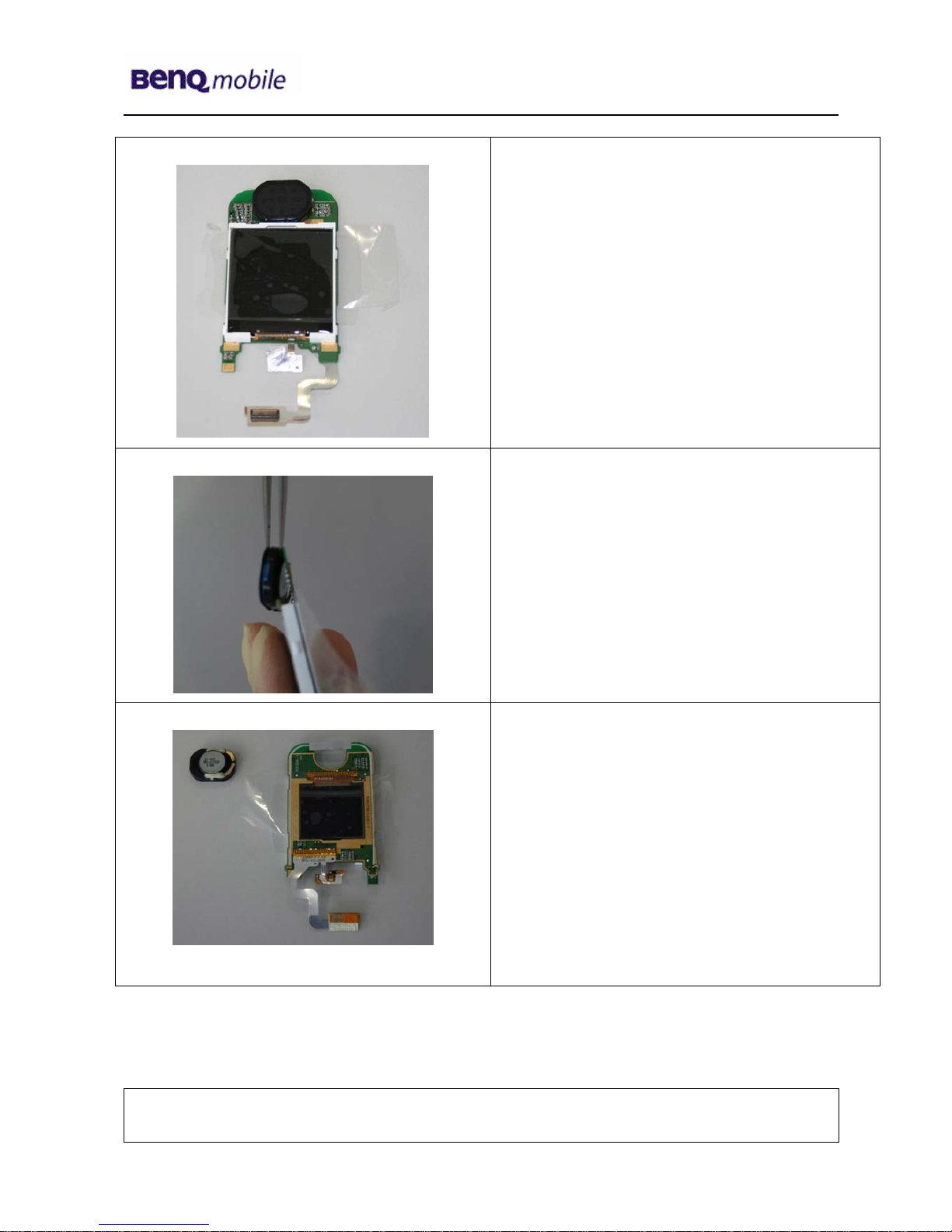
Step 25
To avoid scratches it is mandatory to place a
protection foil onto the Display!!!
Step 26
Disconnect the loudspeaker from PCB with
Tweezers.
Step 27
Company Confidential
2005©BenQ
Release 1.0
Technical Documentation
10/2005
TD_Repair_L2.5L_AF51_R1.0.pdf Page 16 of 56
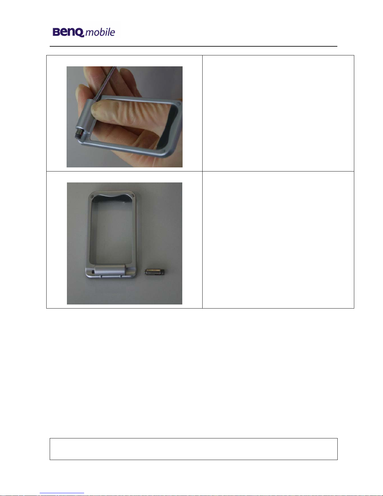
Step 28
Remove Hinge - Spring by pushing it through
the Hinge.
Step 29
Company Confidential
2005©BenQ
Release 1.0
Technical Documentation
10/2005
TD_Repair_L2.5L_AF51_R1.0.pdf Page 17 of 56
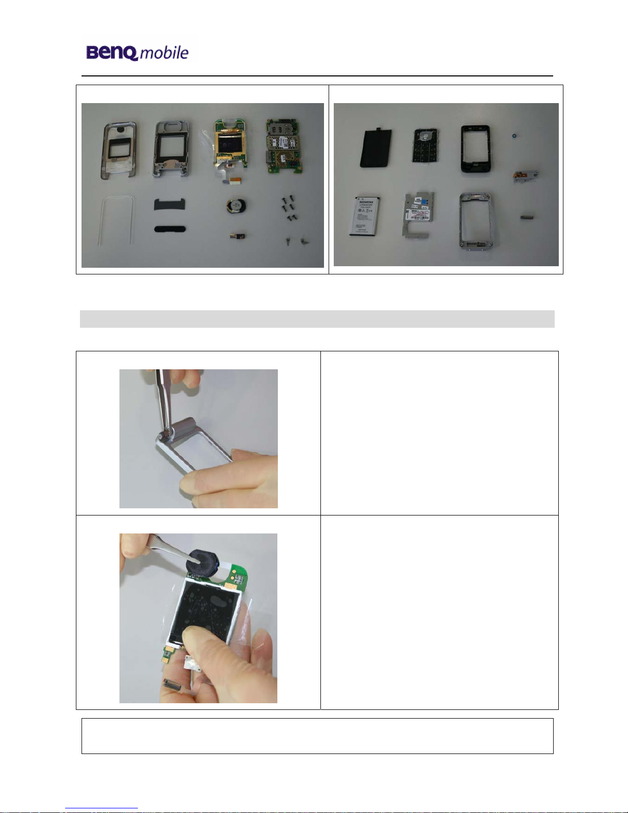
Overview Upper Parts Overview Lower Parts
Screw Cover
Screw Cover
loudspeaker
Micro
p
hone
Antenna
Hin
g
e
Display Module
Spacer
Display
PCB cover
plate
Ke
yp
ad
Upper Base
Frame
Lower Base Frame
PCB
Main PCB
Battery
Vibramotor
Screws
Rear Cover
6 Assembly of AF51
Step 1
Push the Hinge inside the Frame.
Step 2
Assemble mircrophone by using tweezers.
Company Confidential
2005©BenQ
 Loading...