

Page 1

Digital Signage/IFP
Installation Handbook
Page 2

Copyright
Copyright © 2020 by BenQ Corporation. All rights reserved. No part of this publication may
be reproduced, transmitted, transcribed, stored in a retrieval system or translated into any
language or computer language, in any form or by any means, electronic, mechanical, magnetic,
optical, chemical, manual or otherwise, without the prior written permission of BenQ
Corporation.
Disclaimer
BenQ Corporation makes no representations or warranties, either expressed or implied, with
respect to the contents hereof and specifically disclaims any warranties, merchantability or
fitness for any particular purpose. Further, BenQ Corporation reserves the right to revise this
publication and to make changes from time to time in the contents hereof without obligation of
BenQ Corporation to notify any person of such revision or changes.
2
Page 3

Table of Contents
Copyright ...................................................................................................................................... 2
Disclaimer ..................................................................................................................................... 2
Display installation guide ........................................................................................................... 5
Precautions .................................................................................................................................................. 5
Notes on moving the display................................................................................................................... 5
Notes on installing the display................................................................................................................. 7
Notes on using the remote control....................................................................................................... 8
Cable extension guide .............................................................................................................................10
Video wall installation guide ...................................................................................................21
Precautions ................................................................................................................................................ 21
Notes on moving the display................................................................................................................. 21
Installing ...................................................................................................................................................... 21
Installing edge finishing kit: PL460/PH460/PH550/PL550 ................................................................25
Making a daisy chain .................................................................................................................................27
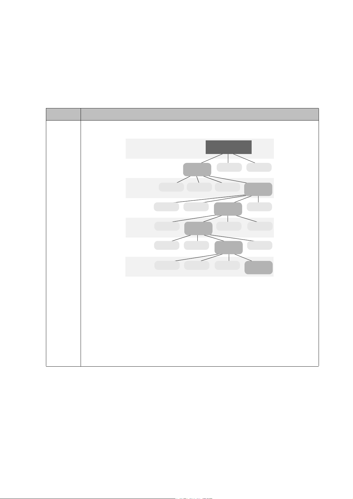
Different types of daisy chain ................................................................................................................ 29
Operating Instructions of Edge Alignment Kit/Pin: PL490/PL552/PL553/PH5501/PH5502 ....40
Tiling: PL490/PL552/PL553/PH5501/PH5502 .....................................................................................44
Special signage installation guide ............................................................................................46
D series Full HD 55-inch dual-side display......................................................................................... 46
Mounting installation ................................................................................................................49
Ceiling Mount............................................................................................................................................ 49
Notice ......................................................................................................................................................... 52
U-Mount .....................................................................................................................................................54
H-mount .....................................................................................................................................................58
Digital Signage Bar-Type Series ..............................................................................................59
Installation notice ..................................................................................................................................... 59
Adjusting the OSD setting: For BH280/BH281/BH380................................................................... 59
BH series HDMI connetion (EXCEPT BH280/BH281/BH380) .....................................................60
Troubleshooting ........................................................................................................................62
Connections............................................................................................................................................... 62
Picture/video .............................................................................................................................................65
Audio........................................................................................................................................................... 68
Remote control......................................................................................................................................... 68
Touch function (selected models only) ...............................................................................................69
OSD menu/control panel/power button ............................................................................................71
LED indicators........................................................................................................................................... 73
Power.......................................................................................................................................................... 73
System: PL460/PH460/PL550/PH550 ...................................................................................................74
Troubleshooting: PL490/PL552/PL553/PH5501/PH5502 ................................................................75
Wall mounting/video wall ....................................................................................................................... 77
3
Page 4

Preventing afterimage burn-in ................................................................................................78
Appendix 1: Installation Checklists ....................................................................................... 79
Before installation.................................................................................................................................... 79
After installation .......................................................................................................................................80
Warranty information .............................................................................................................................81
Appendix 2: Basic Troubleshooting Checklists for IFP & IL series ...............................82
Part I: customer feedback form (customer information and description of problem) ........... 82
Part II: problem resolving attempt & troubleshooting.................................................................... 84
Pictures for reference............................................................................................................................. 89
Appendix 3: Basic Troubleshooting Checklists for Video Wall .....................................90
Part I: customer feedback form (customer information and description of problem) ........... 90
Part II: problem resolving attempt & troubleshooting .....................................................................92
Appendix 4: Basic Troubleshooting Checklists for X-Sign ..............................................96
Part I: customer feedback form (customer information and description of problem) ........... 96
Part II: problem resolving attempt & troubleshooting .....................................................................98
4
5/8/20
Page 5
Display installation guide
To ensure safety, please read this manual carefully before installation and follow the instructions
herein. Store this installation guide in a secure place for future reference.
At the end of this Installation Handbook are installation checklists that help you to ensure the
necessary steps have been completed. Make sure to have the checklists by hand before
performing a new installation.
Precautions
• The display must be installed on a flat and level surface which is strong enough to bear its
weight.
• If the display is mounted with a mounting bracket, make sure the bracket is tightened and
secured on the wall and is strong enough to bear the weight of the display.
• The Liquid Crystal Display (LCD) panel of the display has a very thin protective layer of glass
which is liable to marking or scratching, and cracking if struck or pressured. Please protect
the display with cushions during installation.
• Move a display by holding the handles on the back of the
display. Do not touch the LCD panel directly to avoid
possible scratches. Do not move a display by holding its
frames.
• To maintain proper ventilation and heat dissipation, keep at
least 60 mm of clear space from the mounted displays to
the wall.
Notes on moving the display
The display has limited mechanical strength. To prevent the display from performance failure
caused by line defects, front bezel bending, glass scratch/broken, light leakage, etc, it must be
handled with care. Keep the original shipping box and packaging in storage for use in the future
when you may meed to transport the product.
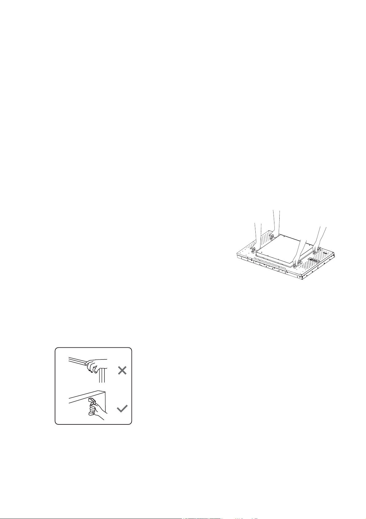
When you want to move the display, make sure the four (4)
handles are held.
5 Display installation guide
Page 6
Always move the display by at least two (2) adults with both
hands.
90° 90°
Lay down the display gently and horizontally.
When you want to place the display face down, prepare a flat
and horizontal surface that is larger than the display and
spread a thick protective sheet on it.
Be careful not to scratch any parts of the display when
upturning the display.
Lift the display up horizontally by holding the four (4) handles.
Do not lift the display against its corner.
6 Display installation guide
Page 7
When you want to upturn the display, stand the display
Alignment
screw
Wall
mount kit
vertically to make sure its weight spread evenly on the surface.
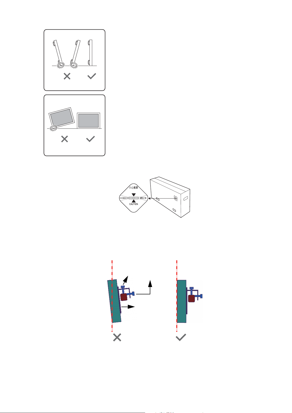
• Check the shock label on the outside of the product carton. The shock indicator on the label
will turn red if the display/package is improperly handled (for PL/PH series only).
Notes on installing the display
Installation of this display should only be performed by two (2) qualified technicians. Failure to
install this display properly may cause injuries and damages to the personnels and the display
itself.
• Be sure to use the alignment screw(s) to set the vertical alignment when installing the display.
• Leave some space in advance when installing the display. Use the alignment screw(s) on the
bracket to reduce the gap between the display to avoid collision.
• It is recommended to use the bracket which can be adjusted vertically and horizontally.
7 Display installation guide
Page 8
• Do not install near any heat source such as radiators, heat registers, stoves, other apparatus
30°
30°
8M
(including amplifiers) that produce heat or put the unit exposed to direct spotlight or sunlight.
• It is highly UNRECOMMENDED to install products in moving vehicles as there is high risk for
breaking the internal hanging-panel films in the long run.
• It is highly UNRECOMMENDED to install products in environments with excessive foreign
particles floating in the air such as open kitchen. Special countermeasures must be taken to
seal the unit completely (leaving some opening for heat dissipation) to minimize the effect of
foreign air particles.
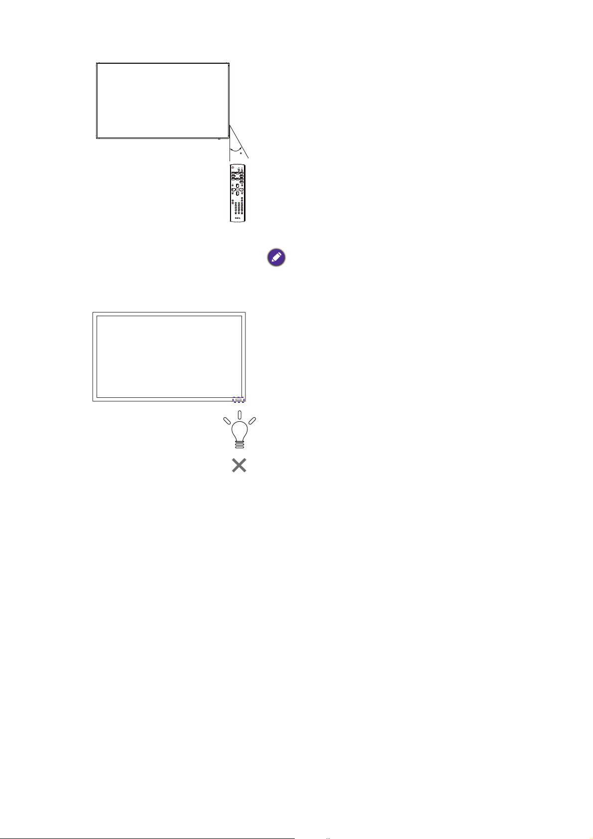
Notes on using the remote control
Point and aim the top front of the remote control directly at the display’s remote control
sensor window when you press the buttons. Do not let the remote control become wet or
place it in humid environments (like bathrooms).
When using the remote control, confirm there is no
object between the remote control and the remote
sensor of the product.
Operate the remote control from a location closer to
the display’s remote control sensor window. Adjust the
distance between the remote control and the display.
Straight-line distance: 8 meters
Transmit angle: ± 30°
The sensor window’s position may vary by models.
8 Display installation guide
Page 9
For IL430/IL490/IL550, when two displays place together,
30
the signal of the remote control is easily interfered by
the Touch screen signal.
• Do not place the remote control receiver of the display
parallel to the front frame of another display or its
signal will be interfered by Touch screen’s signal. Please
keep the distance for at least 20 mm when placing two
monitors side by side.
• Use an IR extender cable (3.5 mm cable) to avoid
interference between IR remote controller and the
Touch Screen when placing multiple displays
side-by-side.
The remote control may not function properly when the
remote control sensor on the display is under direct sunlight
or strong illumination, or when there is an obstacle in the path
of signal transmission.
When using the remote control, make sure the display’s
remote control sensor window is NOT exposed to
direct sunlight or strong reflected light, e.g. tile flooring.
9 Display installation guide
Page 10

Cable extension guide
This guide provides additional information about how to extend VGA, HDMI and USB
connections as required in the environment where you set up your BenQ digital signage and
interactive flat panel displays. Refer to the instructions in this guide and the User Manual of
your BenQ display to ensure stable and optimal performance.
Pay attention to the following notes when you connect cables:
• Turn off all devices before making connections.
• Use certified, high-quality cables and signal amplifiers/repeaters.
• Familiarize yourself with the ports and sockets on the display and the devices you want to
connect. Be aware that incorrect connections may adversely affect picture quality.
• Do not remove cables from the ports and sockets by pulling the cable itself. Always grasp and
pull the connectors at the end of the cable.
• Ensure that all cables are fully inserted and firmly seated for proper pin contact.
10 Display installation guide
Page 11
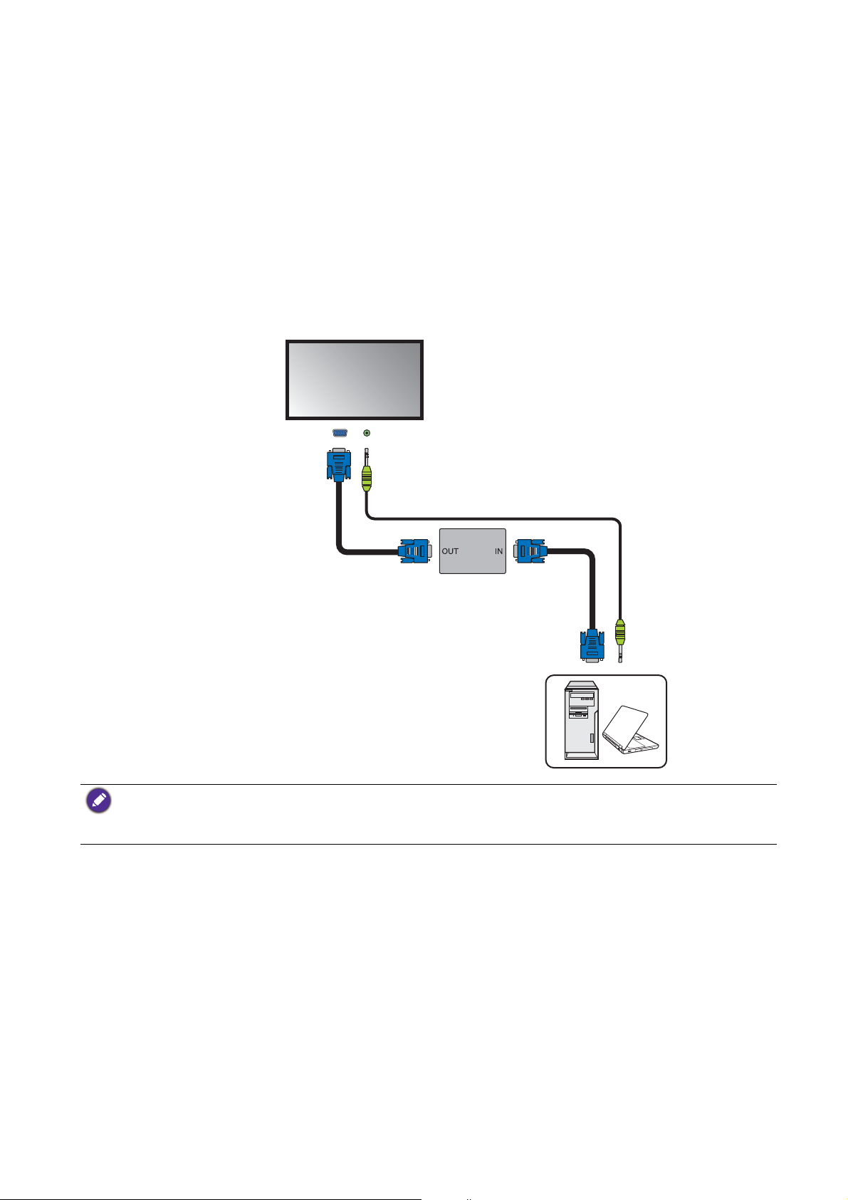
Extending the VGA connection using a VGA amplifier/repeater
D-Sub (15-pin)
cable
Audio cable
Computer
D-Sub (15-pin)
cable
VGA signal
amplifier/repeater
Display
Audio input jackVGA input
jack
If you need to connect the display to a computer or other VGA source devices over a long
distance (over 3 meters), a VGA signal amplifier must be used to boost the signal and prevent
potential display quality problems like interference and ghosting.
1. Connect the VGA input jack on the display to the VGA output jack on the VGA signal
amplifier/repeater using a D-Sub (15-pin) cable.
2. Connect the VGA output jack on the computer to the VGA input jack on the VGA signal
amplifier/repeater using a D-Sub (15-pin) cable.
3. Connect the computer’s audio output jack to the audio input jack on the display using a
suitable audio cable.
• Refer to the User Manual of your display for the location of VGA and corresponding audio input jacks.
• The audio cable, VGA signal amplifier/repeater and additional VGA cable are not supplied and should be
purchased separately.
11 Display installation guide
Page 12
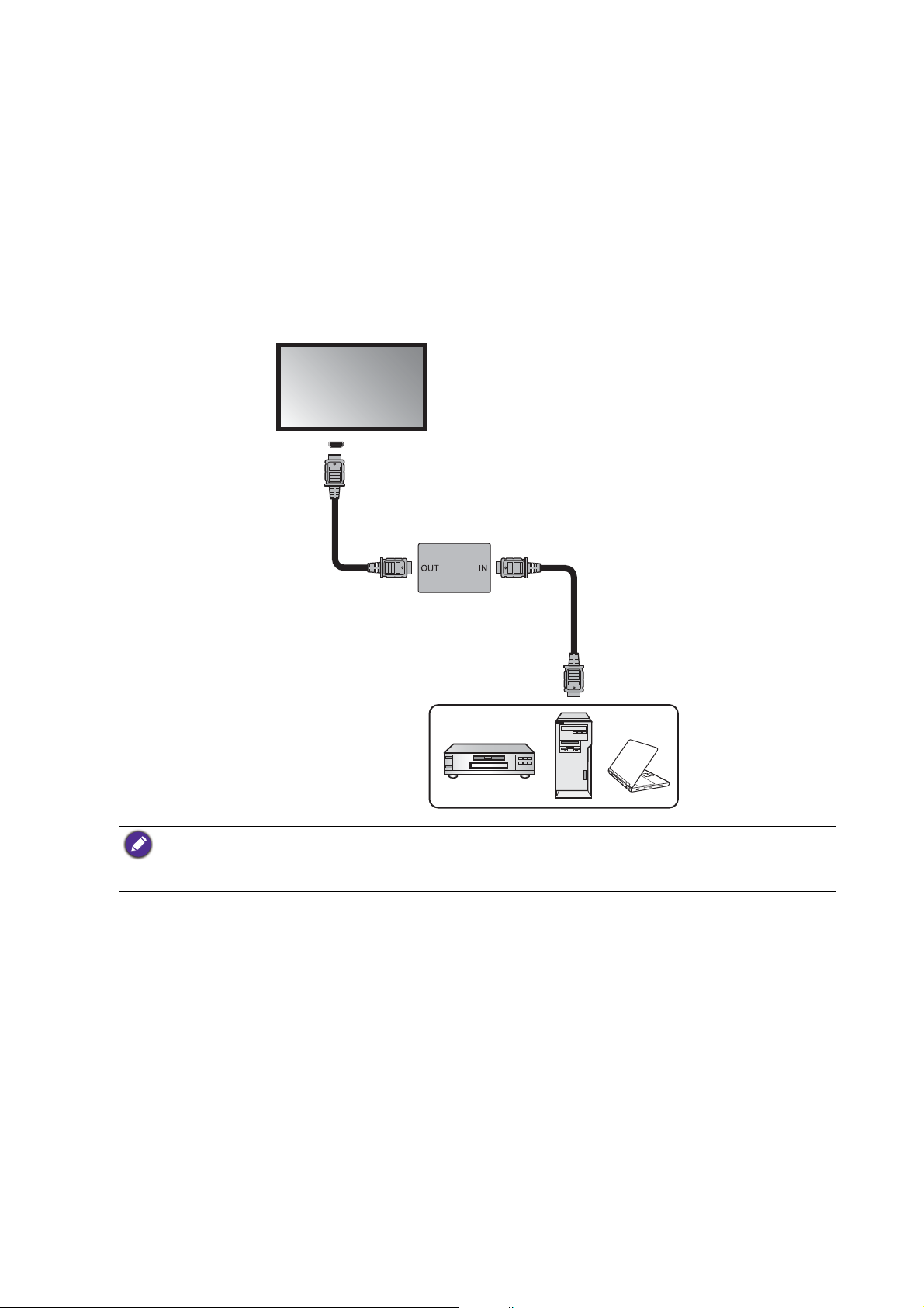
Extending the HDMI connection using an HDMI amplifier/repeater
HDMI cable
HDMI cable
DVD/Blu-ray player or
computer
HDMI signal
amplifier/repeater
HDMI input jack
Display
Although there is not an official limit on HDMI cable length (as it mainly depends on the quality
of the HDMI cable), in order to prevent potential display quality problems like interference and
ghosting, if you need to connect the display to a computer or an A/V device (such as a DVD or
Blu-ray player) over 5 meters, deployment of an HDMI signal amplifier is highly recommended.
1. Connect the HDMI input jack on the display to the HDMI output jack on the HDMI signal
amplifier/repeater.
2. Connect the HDMI input jack on the HDMI signal amplifier/repeater to the HDMI output
jack on the HDMI source device using an HDMI cable.
• Refer to the User Manual of your display for the location of HDMI input jacks.
• The HDMI cables and HDMI signal amplifier/repeater are not supplied and should be purchased
separately.
12 Display installation guide
Page 13
Connecting faceplate
Faceplate
USB cable
Computer
USB cable
Display
USB port
1. Connect the mini-B plug of the supplied USB cable to the USB Mini-B port on the display,
and the type-A plug of the cable to the USB port on the faceplate.
2. Connect the computer to the faceplate using a suitable USB cable.
• Refer to the User Manual of your display for the location of USB port.
• Any cable used in prior installations for other displays and projectors in the same location should not be
used for a new installation of the display.
• Use only a high-quality faceplate.
• The total cable length between the display, computer and faceplate should not exceed 5 meters. If you
need to extend the length of USB connection, refer to "Extending USB connection" on page 14.
13 Display installation guide
Page 14
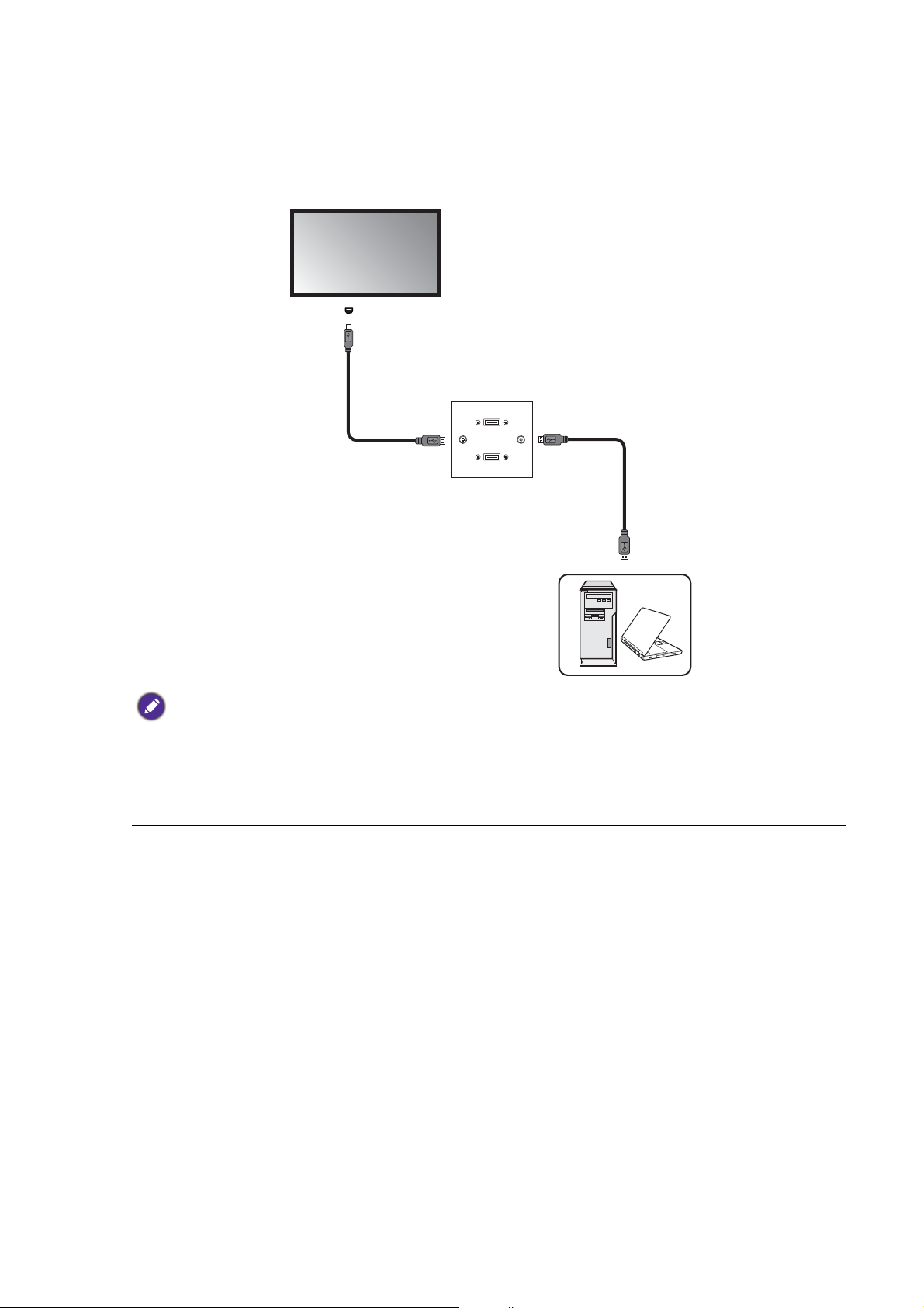
Extending USB connection
USB cable
Active USB
extension cable
Computer
Display
USB port
Extending USB connection using an active (powered) USB extension cable
You can use a commercially available active (powered) USB extension cable on the market to
extend the length of USB connection. The active USB extension cable helps boost the USB
signal as well as provides sufficient bus power for the connected USB device.
1. Connect the mini-B plug of the supplied USB cable to the USB Mini-B port on the display,
and the type-A plug of the cable to the USB type-A port on the active USB extension cable.
2. Connect the type-A plug of the active USB extension cable to the USB port of a computer.
• Refer to the User Manual of your display for the location of USB port.
• For best results, use only a certified active USB extension cable.
• The type of USB port and plug on the active USB extension cable may be different from the description
above. Use a USB cable that matches the USB jack on the display and the USB port on the extension
cable.
• The length of the USB cable used to connect the display to the USB extension cable should not exceed 5
meters.
Extending USB connection using an active (powered) USB-CAT converter
You can use a commercially available active (powered) USB-CAT converter (extender) on the
market to extend the length of USB connection over a Category 5/5e/6 network cable.
1. Connect the mini-B plug of the supplied USB cable to the USB Mini-B port on the display,
and the type-A plug of the cable to the USB type-A port on the active USB-CAT converter.
2. Connect a Category 5/5e/6 network cable to the RJ-45 LAN ports on the converter.
14 Display installation guide
Page 15
3. Connect the converter to a computer using a suitable USB cable.
USB cable
Category 5/5e/6
network cable
USB cable
USB-CAT converter
Computer
Display
USB port
• Refer to the User Manual of your display for the location of USB port.
• Refer to the documentation of the active USB-CAT5 converter for the maximum length of the Category
5/5e/6 network cable.
• The type of USB port and plug on the active USB-CAT converter may be different from the description
above. Use a USB cable that matches the USB jack on the display and the USB port on the active USBCAT converter.
• Keep the Category 5/5e/6 network cable away from power lines and cables to avoid electronic
interference.
Extending USB connection using an active (powered) USB extension cable and a
faceplate
Depending on the environment where you install the display, you can use an active (powered)
USB extension cable to extend USB connection from a faceplate.
1. Connect the mini-B plug of the supplied USB cable to the USB Mini-B port on the display,
and the type-A plug of the cable to the USB type-A port on the active USB extension cable.
2. Connect the type-A plug of the active USB extension cable to the USB port on the
faceplate.
15 Display installation guide
Page 16
3. Connect the computer to the faceplate using a suitable USB cable.
USB cable
Active USB
extension cable
USB cable
Computer
Faceplate
Display
USB port
• Refer to the User Manual of your display for the location of USB port.
• For best results, use only a certified active USB extension cable and high-quality faceplate.
• The type of USB port and plug on the active USB extension cable may be different from the description
above. Use a USB cable that matches the USB jack on the display and the USB port on the extension
cable.
• The total length of the USB cables used to connect the display to the active USB extension cable and
computer to the faceplate should not exceed 5 meters.
Extending USB connection using an active (powered) USB-CAT converter and a
faceplate
Depending on the environment where you install the display, you can use an active (powered)
USB-CAT converter to extend USB connection from a faceplate.
1. Connect the mini-B plug of the supplied USB cable to the USB Mini-B port on the display,
2. Connect a Category 5/5e/6 network cable to the RJ-45 LAN port on the converter.
3. Connect the converter to the faceplate using a suitable USB cable.
and the type-A plug of the cable to the USB type-A port on the active USB-CAT converter.
16 Display installation guide
Page 17
4. Connect the computer to the faceplate using a suitable USB cable.
USB cable
USB-CAT converter
USB cable
Category 5/5e/6
network cable
Computer
USB cable
Faceplate
Display
USB port
• Refer to the documentation of the active USB-CAT converter for the maximum length of the Category
5/5e/6 network cable.
• The type of USB port and plug on the active USB-CAT converter may be different from the description
above. Use a USB cable that matches the USB jack on the display and the USB port on the active USBCAT converter.
• Keep the Category 5/5e/6 network cable away from power lines and cables to avoid electronic
interference.
• The total length of the USB cables used to connect the display to the active USB-CAT converter,
converter to the faceplate and computer to the faceplate should not exceed 5 meters.
17 Display installation guide
Page 18
Additional information
Tier 1 (root tier)
Tier 7
Tier 6
Tier 5
Tier 4
Tier 3
Tier 2
Function Function
Host
Root hub
Function FunctionFunction
Hub A
Hub A
Function Function
Hub A
Hub C
Hub A
Hub B
Function
Function Function
Hub A
Hub D
Function
Function Function
Hub A
Hub E
Function
Function Function
Hub A
Hub F
Function
Your LCD display provides USB 2.0 ports for connecting to various devices including
computers, flash drives and wireless LAN adapters. This section provides basic information
about the USB 2.0 interface and serves as a reference for the deployment of your USB
connections.
USB terminology
Te r m Description/explanation
Host,
Function
A USB network consists of one master and multiple slave devices in a star
topology as illustrated below:
The master device (referred to as the “Host”) is on top of all other slave devices
(called “Function”). A computer is the most common USB host. Any device that
has a USB host controller and related hardware and software installed can also
become a USB host. A USB function can be a USB mouse, keyboard or storage
device.
18 Display installation guide
A maximum of 7 tiers (including the root tier) are allowed in a single USB
network. Note that a USB device that performs both as a hub and a function
occupies two tiers.
Page 19
Te r m Description/explanation
Upstream The direction of data transmission from a USB function to a host or hub.
Downstream The direction of data transmission from a USB host or hub to a function.
Hub A USB device that provides upstream connection (port) to a host and
downstream connections (ports) to multiple functions.
Root hub A USB host that also performs the functions of a hub.
Speed (low-speed,
Three different speeds are currently defined in the USB 2.0 specification:
full-speed and highspeed)
• Low-speed: data transmission at 1.5Mbps
• Full-speed: data transmission at 12Mbps
• High-speed: data transmission at 480Mbps
The actual transmission speed is determined by the device with the
lower (or lowest) speed. For example, if a low-speed (1.5Mbps) USB
peripheral is connected to a high-speed (480Mbps) USB host, the
maximum transmission speed between these devices will be 1.5Mbps,
not 480Mbps.
Active (self-
powered) device
Passive (bus-
powered) device
A USB device that has it own power supply and can operate without the
power supplied by the USB host.
A USB device that does not have its own power supply and solely relies
on the power supplied by the USB host.
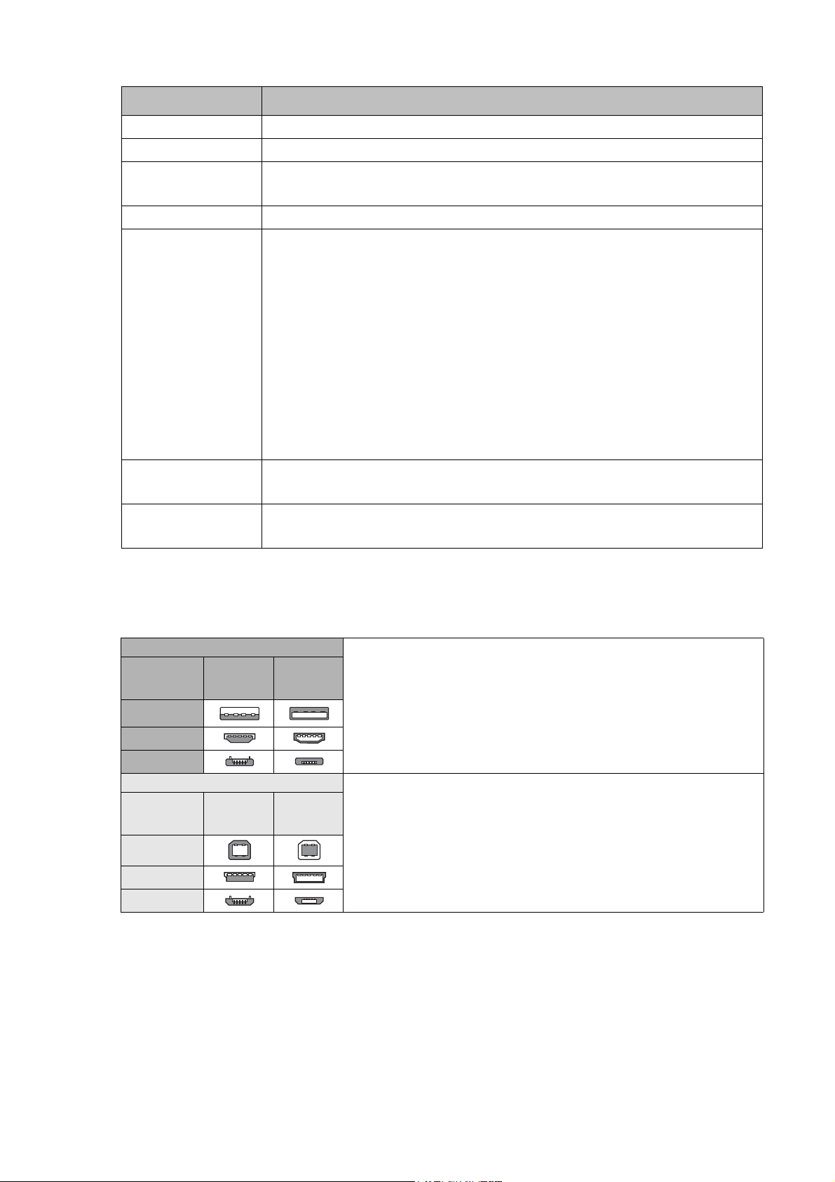
USB connectors and receptacles
USB connectors and receptacles are grouped into two types: Type-A and Type-B.
Ty p e - A
ConnectorRecepta
cle
Standard
Mini
Micro
Ty p e - B
ConnectorRecepta
cle
Standard
Mini
Micro
USB cable length
For each passive connection between a two USB devices, the maximum length for USB 3.0 is 3
meters, and the maximum length for USB 2.0 is 5 meters. To extend USB connection beyond
this length limit, an active extension cable has to be used to ensure stable signal transmission
and reliable power supply.
• Type-A receptacles are used as outputs from host systems
and hubs.
• Type-A plugs are always oriented towards the host system
and mate with Type-A receptacles.
• Type-B receptacles are used as inputs to hubs or devices.
• Type-B plugs are always oriented towards a USB hub or
device and mate with Type-B receptacles.
19 Display installation guide
Page 20

Prohibited cable assemblies
Some cable assemblies are prohibited in the USB specifications and are not recommended as
they may not work in all instances. For example, passive extension cable assembly: a cable that
has a Type-A plug on one end and a Type-A receptacle on the other, or a Type-B plug on one
end and a Type-B receptacle on the other. This allows multiple cable segments to be connected
together, possibly exceeding the maximum permissible cable length.
20 Display installation guide
Page 21

Video wall installation guide
To ensure safety, please read this manual carefully before installation and follow the instructions
herein. Store this installation guide in a secure place for future reference.
At the end of this Installation Handbook are installation checklists that help you to ensure the
necessary steps have been completed. Make sure to have the checklists by hand before
performing a new installation.
Precautions
• The video wall must be installed on a flat and level surface which is strong enough to bear its
weight.
• If the video wall is mounted with mounting brackets, make sure the brackets are tightened
and secured on the wall and are strong enough to bear the weight of the video wall.
• The Liquid Crystal Display (LCD) panel of the display has a very thin protective layer of glass
which is liable to marking or scratching, and cracking if struck or pressured. Please protect
the display with cushions during video wall installation.
• Move a display by holding the handles on the back of the display. Do not touch the LCD panel
directly to avoid possible scratches.
• To maintain proper ventilation and heat dissipation, keep at least 60 mm of clear space from
the mounted displays to the wall.
• Ensure enough gap between displays to protect your LCD screens from the damage through
the direct transfer of weight. See Checking the safe distance between displays on page 23 for
details.
Notes on moving the display
The display has limited mechanical strength. To prevent the display from performance failure
caused by line defects, front bezel bending, glass scratch/broken, light leakage, etc, it must be
handled with care. Refer to Notes on moving the display on page 5.
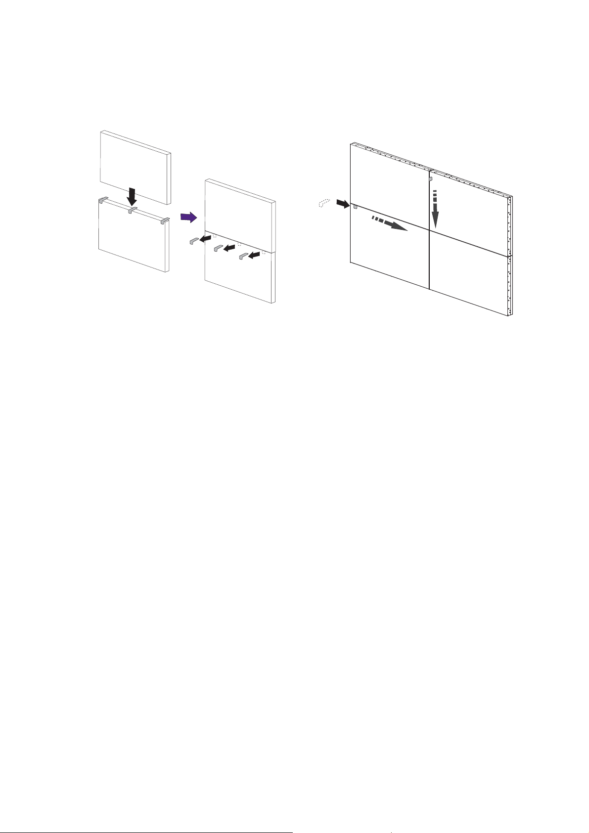
Installing
You can cascade the displays in landscape or portrait mode as desired. Mind the space between
displays during installation.
Cascading displays in landscape or portrait mode
1. Install the mounting bracket to the wall following the instruction manual of the wall
mounting bracket. Make sure the mounting bracket is vertically and horizontally placed.
2. Attach the provided gap inspection pads to the display edges as instructed in Step 1~3 in
Checking the safe distance between displays on page 23.
3. Mount and fasten the display on the mounting bracket or stand by tightening the screws
through the respective holes with a Phillips (cross) screwdriver. Do not place one display
directly on another as the stacked LCD screens may be damaged by the weight.
21 Video wall installation guide
Page 22
4. Start your video wall from the bottom left or bottom right. Finish one row and then
Landscape mode Portrait mode
Rotate each display 90 degrees clockwise to
install the video wall in portrait mode.
For height adjustment
For tilt adjustment 1
For tilt adjustment 2
For height adjustment
For tilt adjustment
(Recommended)
(Not recommended)
move up to finish the next row. Once a display has been installed, check the horizontal
and vertical level immediately using a professional measuring tool.
5. Place your displays as close to each other
as possible but an appropriate space of at
least 0.5 mm should be kept. Check the
gap between displays as instructed in Step
4~5 in Checking the safe distance between
6. To maintain proper ventilation and heat
dissipation, keep at least 60mm of clear
space from the mounted displays to the
wall.
60mm
(1.52")
displays on page 23.
Various mounting brackets may be available to you, but only some of them are suitable for a video wall.
22 Video wall installation guide
Page 23
Checking the safe distance between displays
Adhesive tape with peeling sheet
Front panel
During video wall installation, you might want to place the displays as close to each other as
possible. Note the LCD screens may be damaged through the direct transfer of weight if an
appropriate distance is not kept between displays. The recommended gap between displays may
vary depending on your purchased models as listed below.
Model name Recommended gap between displays
P Series ≥ 0.5 mm
Actual bezel-to-bezel dimensions may exceed the listed minimum values (5.4mm for
PH460/PL460, 3.5mm for PL490/PL550/PL552/PH5501, 1.8 mm for PL553/PH5502, 0.88mm for
PL5502) due to different tiling methods.
You are provided with gap inspection pads to ensure appropriate space between the cascaded
displays during video wall installation.
1. Get one of the provided gap inspection
pads and fold it as illustrated.
2. Remove the peeling sheet from the gap
inspection pad.
3. Stick the pad to the edge where another display will be stacked as illustrated. Each edge
should have 3 gap inspection pads attached.
23 Video wall installation guide
Page 24
4. After the displays are mounted and
fastened, check if the space between each
display is just enough for removing the gap
inspection pad smoothly. If the pad is
trapped, adjust the screws to release
more space.
5. Insert the pad again and swipe the pad
horizontally and vertically between the gap
to ensure it can move smoothly. Ignore
the black tapes on the edge if they stop
you. Refer to Recommended gap between
displays on page 23 for the minimum
distance required for each model.
24 Video wall installation guide
Page 25
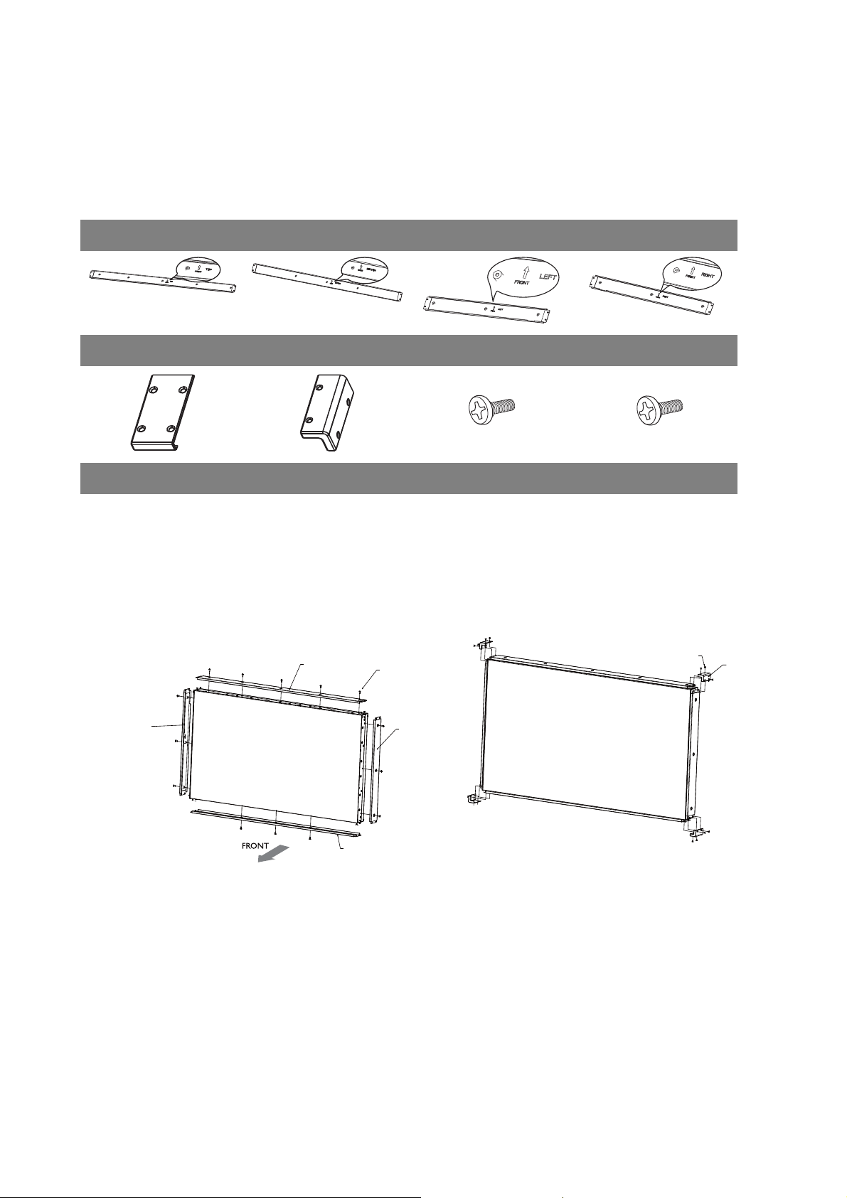
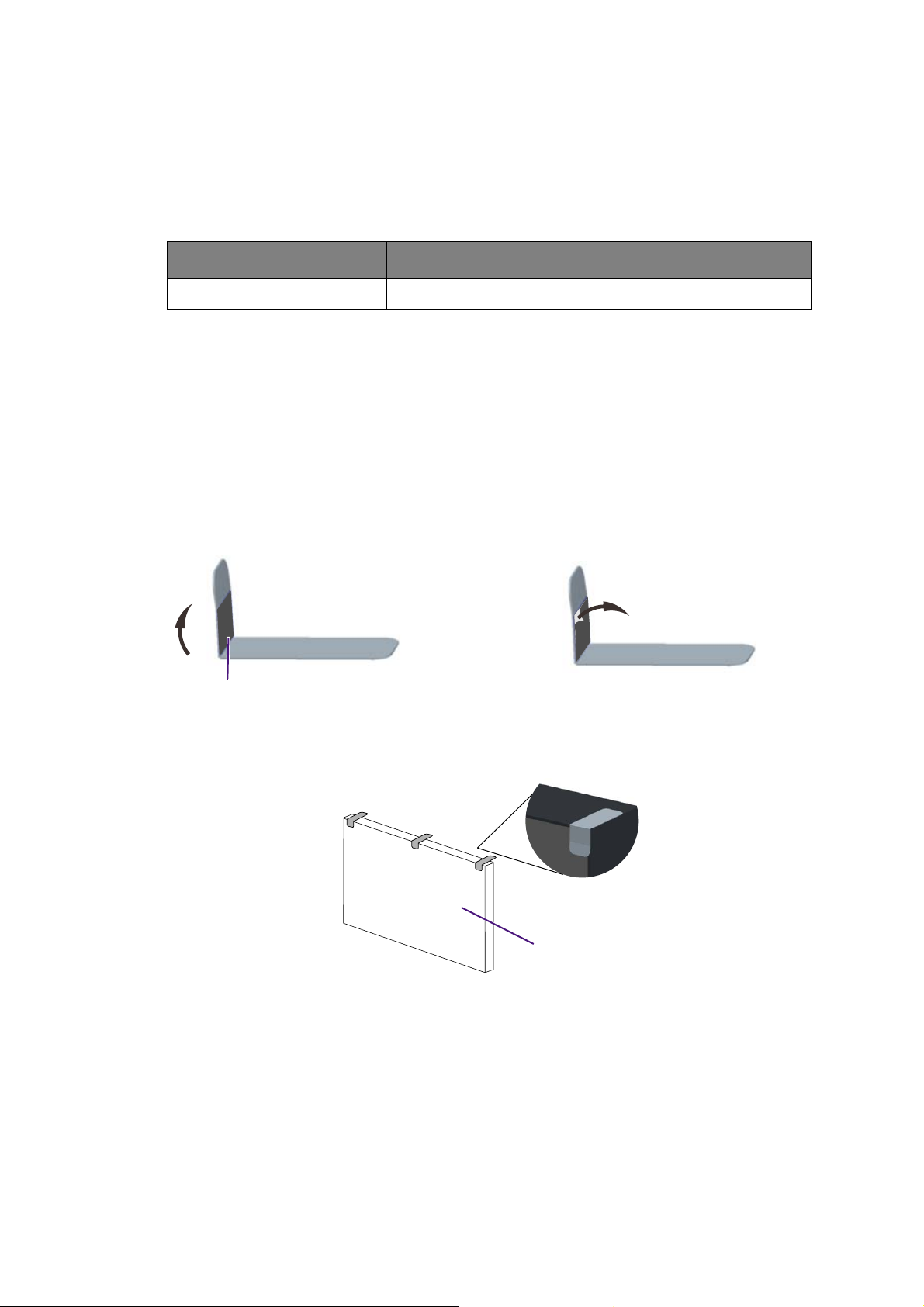
Installing edge finishing kit: PL460/PH460/PH550/PL550
A
H
D
B
C
Whether used as a standalone unit or as a part of a video wall, the edge finishing kit will
transform your display into a most stylish and elegant display.
Inside your edge finishing kit you will find the following components:
Cosmetic Plates
Top (A) Bottom (B) Left (C) Right (D)
Flat Enclosure (E) Corner Enclosure (F) M3 x 5 mm Screw (G) M4 x 6 mm Screw (H)
Installation
For standalone unit
1. Mount the cosmetic plates in their
respective places on the edge of your
display, and screw in to place using the
6mm M4 screws.
2. On each corner, mount a corner enclosure
piece and fasten each one with 4 of the
5mm M3 screws.
G
F
25 Video wall installation guide
Page 26
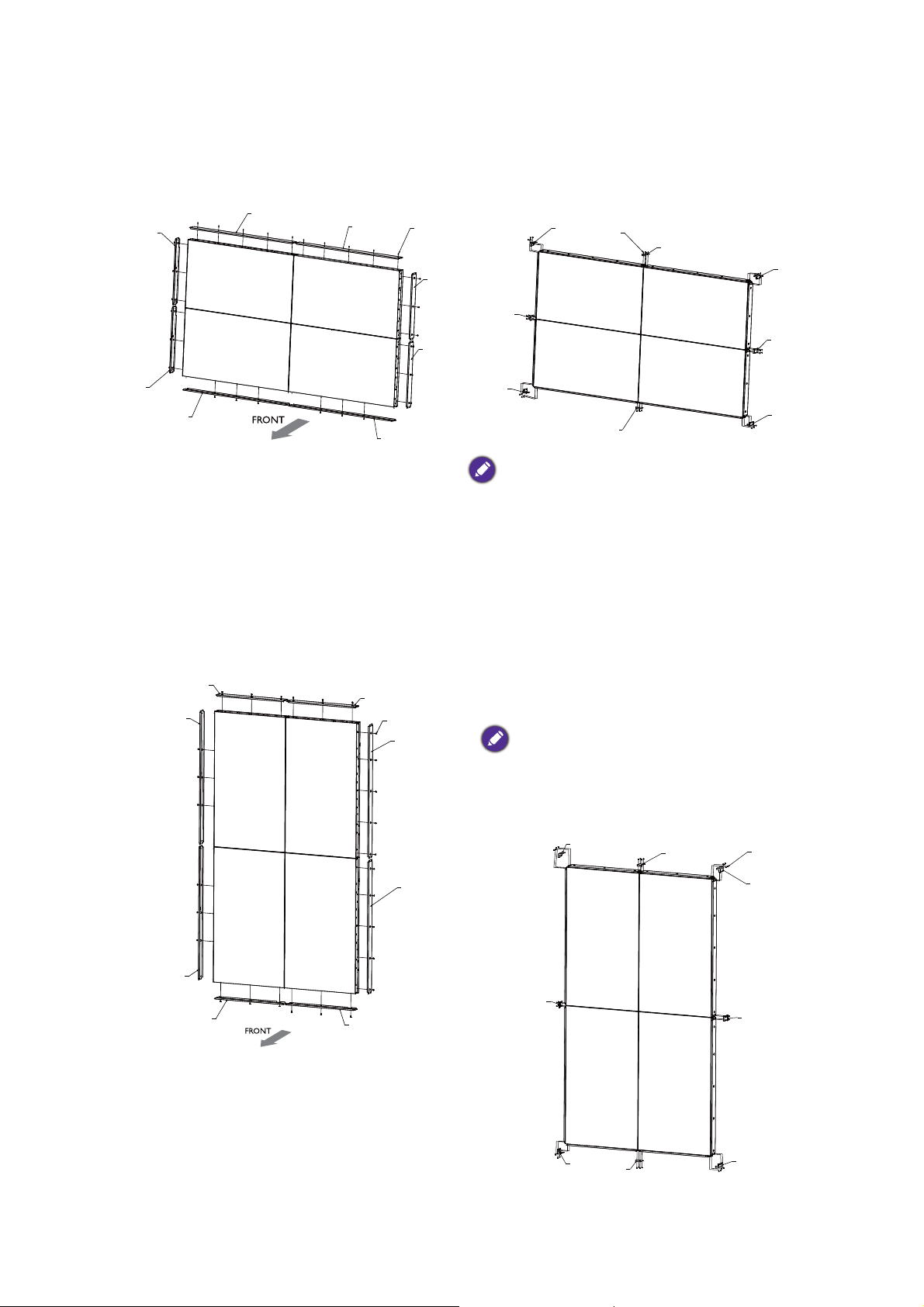
For a landscape video wall
A
A
H
D
D
B
B
C
C
F
E
G
F
E
F
E
F
E
C
H
A
A
D
D
B
B
C
F
E
F
E
F
E
F
E
G
1. Mount the cosmetic plates in their
respective places on the edge of your
display, and screw in to place using the
6mm M4 screws.
For a portrait video wall
2. On each corner, mount a corner enclosure
piece and fasten each one with 4 of the
5mm M3 screws. Where the displays meet,
use a flat enclosure piece, and fasten each
of these too with 4 of the 5mm M3 screws.
When mounting, make sure that all edge enclosure
pieces are fitted to the respective positions (i.e.
bottom to bottom, etc.)
1. Mount the cosmetic plates in their respective places on the edge of your display, and
screw in to place using the 6mm M4
screws.
2. On each corner, mount a corner
enclosure piece and fasten each one with
4 of the 5mm M3 screws. Where the
displays meet, use a flat enclosure piece,
and fasten each of these too with 4 of the
5mm M3 screws.
When mounting, make sure that all edge
enclosure pieces are fitted to the respective
positions (i.e. bottom to bottom, etc). When
rotating, the RIGHT side of the displays should be
on the bottom.
26 Video wall installation guide
Page 27
Making a daisy chain
X
Y
12
43
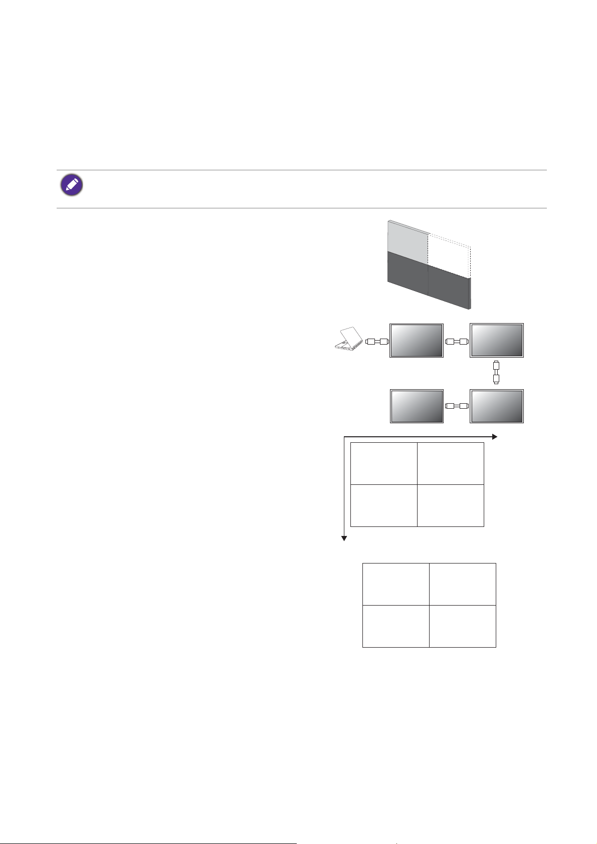
Once you have installed the video wall, you are ready to connect all displays serially as a daisy
chain for playback or centralized management.
Follow the steps below to form a daisy chain, and refer to the mentioned sections for more
information.
In this chapter, illustrations of 4 daisy chained displays are for your reference only. You can connect more displays
if needed, as long as it is within the limit of each daisy chain to ensure picture quality. See Number of daisy
chained displays on page 30 for more information.
1. Install the video wall. Follow the instructions in
Video wall installation guide on page 21.
2. Connect the video source (e.g. computer) and
loop all displays using the required cables. See
Cable connections on page 28 and Cable
extension guide on page 10 for more information.
3. Set the horizontal and vertical position of the
display wall matrix. This helps your computer
identify how many displays are connected and how
to display the image. See Setting the display
position on page 31 for more information.
4. Set the ID number of each display for video wall
management. See Setting the ID number of each
display: PL460/PH460/PL550/PH550 on page 34 for
more information.
27 Video wall installation guide
Page 28
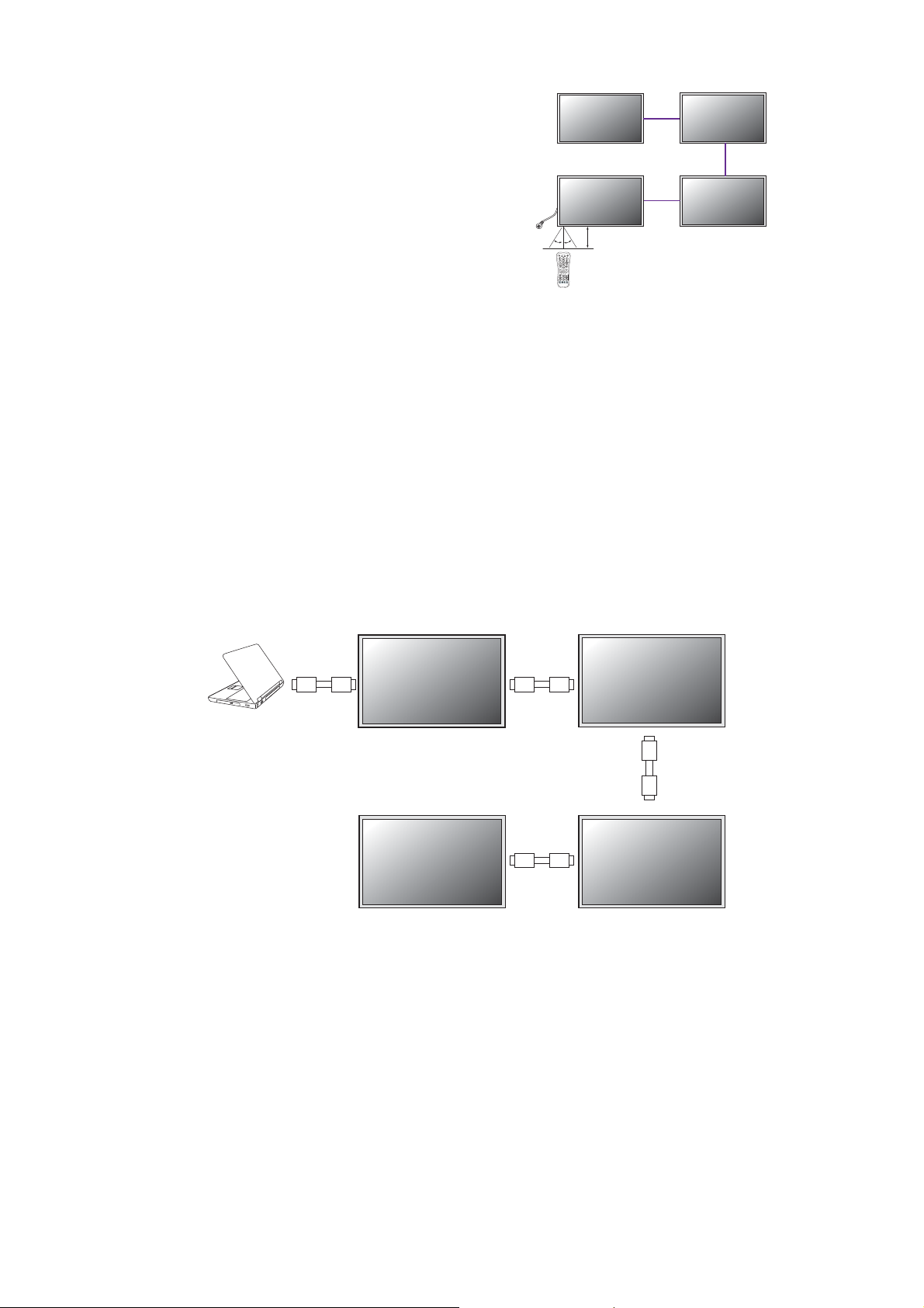
5. Decide the way to manage all the daisy chained
(in) (in)
(in)
(in)
(out)
(out)
(out)
displays. See Managing the daisy chain:
PL460/PH460/PL550/PH550 on page 35 for more
information.
30°30°
6. Change the display settings to optimize video wall
performance as suggested.See Optimizing the
video wall performance and management: PL460/
PH460/PL550/PH550/PL490/PL552/PL553/PH5501
/PH5502 on page 38 for more information.
Cable connections
1. Turn off all devices.
2. Connect the first display with the video source (e.g. computer).
3. Connect one end of the cable to the appropriate OUT port on the first display.
4. Connect the other end of the cable to the appropriate IN port on the second display.
Follow Step 2 ~ 3 to connect all displays.
Refer to the user manual of the purchased model for the location of all input and output
ports.
28 Video wall installation guide
Page 29
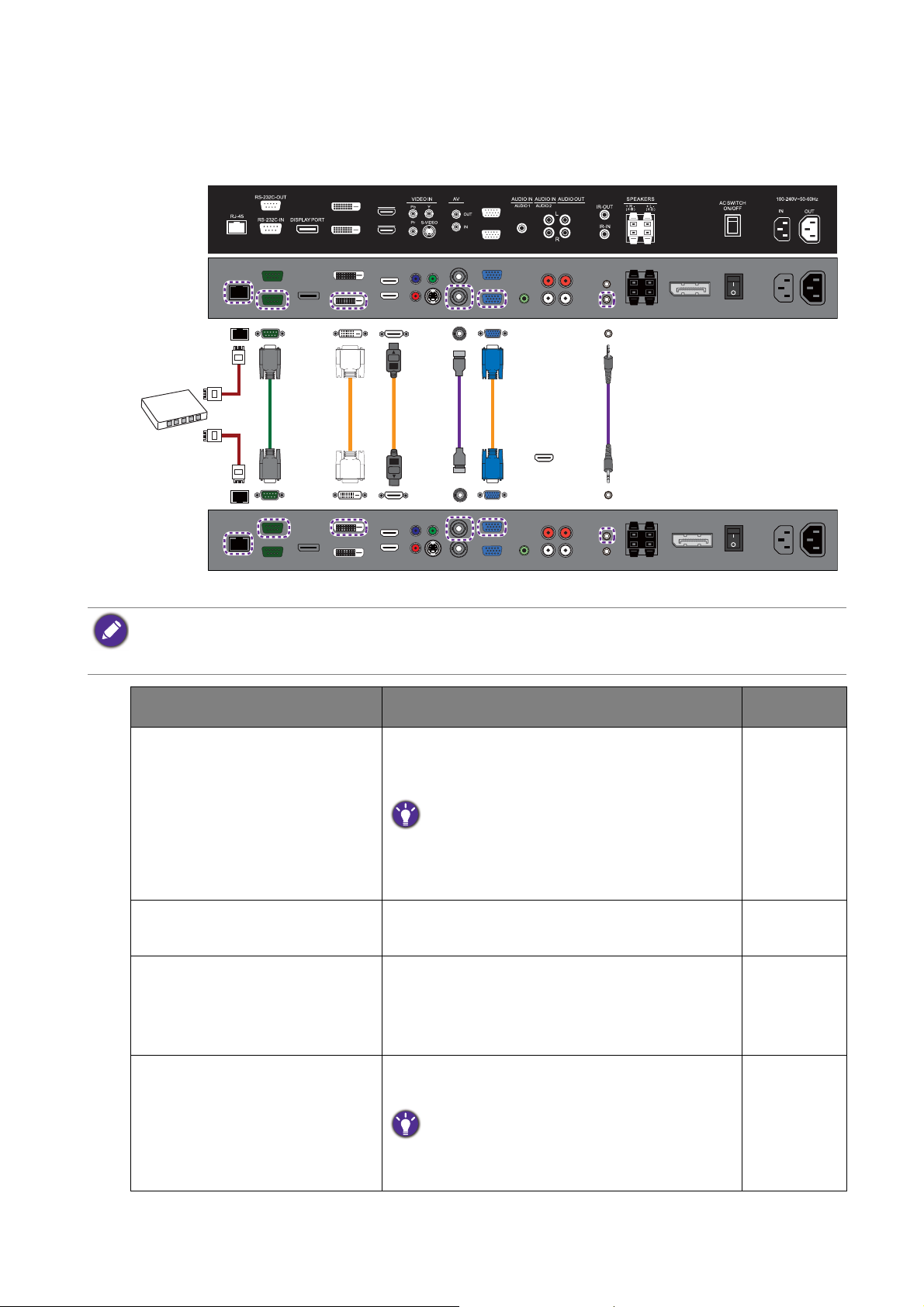
Different types of daisy chain
DVI-OUT
DVI-IN
HDMI-2
HDMI-1
VGAOUT
VGAIN
RS-232C
cable
DVI
cable
AV
cable
D-Sub
(15-pin)
cable
IR cable
The first display (connected to the OUT ports)
The second display (connected to the IN ports)
RJ45
cable
LAN
switch
HDMI
cable
Depending on your needs and input source, different cables should be connected properly.
• Not all cables and daisy chains are available for all models. Check the specifications of the purchased model for
the available connections.
• For cables that are not supplied with your product, you can purchase them separately.
Function Cables required for each display Reference
Video signal transmission • D-Sub/Composite cable for analog signals
Audio signal transmission
(selected models only)
OSD control or advanced
control of all displays via
remote control
(selected models only)
Control of all displays by
RS-232 commands
• DVI/HDMI/DP cable for digital signals
D-Sub, Composite, and DVI support daisy
chaining. If the video output is HDMI, you can use
an adapter to convert the signal into either DVI
or Composite before making the daisy chain.
Audio cable
IR cable Page 35
RS-232C cable.
Use an appropriate RS-232C cable. Refer to the
user manual or BenQ service for more
information.
Page 36
29 Video wall installation guide
Page 30
Function Cables required for each display Reference
Control of all displays through
RJ45 cable Page 36
Local Area Network (LAN)
Number of daisy chained displays
The number of displays you can loop out serially depends on the resolution and type of the
input signal. Refer to the following table for the recommended and maximum number of
displays for different daisy chains.
Input signal Recommended number of display
DVI-I (Analog) 4 9
DVI-I (Digital signal) 16 25
DP PL/PH series: 9
SL series: 16
If connection of more than the maximum number is required, use appropriate signal splitters to ensure stable
signal transmission, and you can loop up to 100 displays for PL460, PH460, PH550 and 225 displays for PL490,
PL550, PL552, PL553, SL490, SL550, PH5501, PH5502, PL5502.
The design of ID setting is different by models.
PL490/PL550/PL552/PL553/SL490/SL550/PH5501/PH5502/PL5502: 15 x 15
PL460/PH460/PH550: 10 x 10
Maximum number of display
(without a signal splitter)
PL/PH series: 12
SL series: 25
30 Video wall installation guide
Page 31
Setting the display position
Video sources
After all the displays are installed properly to a video wall, you need set the position of each
display to determine how to display the input image.
Without setting the display position, each display outputs the complete picture independently.
Once the position is set, the video source (e.g. computer) identifies the number of connected
displays and transfer part of the picture to each display accordingly. The video wall then outputs
one picture as a whole.
If you prefer to show different pictures on the displays of the video wall, you will need to have
independent video source for each display.
Though the video sources vary, you can still manage all displays via remote control, RS-232 commands, or LAN
control in this case.
31 Video wall installation guide
Page 32

Setting the display position in landscape mode: PL460/PH460/PL550/PH550
(H=1.V=1) (H+1.V=1)
(H+1.V+1)(H=1.V+1)
X
(Represented as H for
horizontal position.)
Y
(Represented as V for vertical position.)
(1.1)
(2.1)
(2.2)(1.2)
(1.1) (2.1) (3.1) (4.1)
(1.1)
(1.2)
(1.3)
(1.4)
(1.1) (2.1) (3.1)
(1.2) (2.2) (3.2)
(1.3) (2.3) (3.3)
If a landscape video wall has been installed, follow the procedures to set the display position.
1. Go to Screen > Display Wall > H. Monitors and V. Monitors on each display to set
the total number of displays counted horizontally and vertically.
2. Go to Screen > Display Wall > H. Position and V. P os i ti on on each display to set
the position. The position is defined by the X-Y matrix. Starting from the top left of the
video wall, the number increases as it goes down or goes to the right.
Different video wall layouts and display position setup
Set the display position carefully according to the video wall layout to ensure correct picture
output. Following are some examples for your reference.
32 Video wall installation guide
Page 33

Setting the display position in portrait mode
(H=1.V=1) (H+1.V=1)
(H+1.V+1)(H=1.V+1)
Y
(Represented as V for vertical position.)
X
(Represented as H for horizontal
position.)
(1.1) (2.1)
(2.2)(1.2)
(1.1) (2.1) (3.1) (4.1)
(1.3)
(1.2)
(1.1)
(2.3)
(2.2)
(2.1)
(3.3)
(3.2)
(3.1)
If a video wall in portrait mode is desired, follow the procedures and refer to the matrix and
examples for setup.
1. Rotate each display 90 degrees clockwise to install the video wall in portrait mode.
2. Rotate the picture 90 degrees counterclockwise from your video source (e.g. computer).
3. Rotate the OSD menu from each display. Go to Setting > Advanced > OSD Rotation
and set it to Portrait. Alternatively, wait until the IR loop is created, then change the
setting on one display to apply to all displays. See Management by remote control (selected
models only) on page 35 for more information.
4. Go to Screen > Display Wall > H. Monitors and V. M oni tor s on each display to set
the total number of displays counted vertically and horizontally.
5. Go to Screen > Display Wall > H. Position and V. Po si t io n on each display to set
the position. The position is defined by the X-Y matrix. Starting from the top left of the
video wall, the number increases as it goes down or goes to the right.
Different video wall layouts and display position setup
Set the display position carefully according to the video wall layout to ensure correct picture
output. Following are some examples for your reference.
33 Video wall installation guide
Page 34

Setting the ID number of each display: PL460/PH460/PL550/PH550
12
43
1234
1
2
3
4
123
456
789
Once you have installed the video wall, you need to set an ID number for each display to
identify one among the multiple displays easily. This is helpful for video wall management, such
as power management, OSD control, or color management. It is also helpful if additional
adjustment is required for a specific display.
To set the ID number, go to Setting > Set Monitor ID on each display for configuration. Pay
attention not to set the same ID number for different displays, as the commands for video wall
management would not be received correctly.
Set the ID number starting from 1 to 98, depending on the number of displays daisy chained.
There is no specific direction while going through all displays setting up the ID numbers.
Following are some examples for your reference.
To set the ID number of each display for PL490/PL552/PL553/PH5501/PH5502, adjust the ID number for
controlling the display via the RS232C connection. Each display must have a unique ID number when multiple sets
of this display are connected. Monitor ID number range is between 1 to 225. The default setting is 1.
All models of MDA only support from 1-98.
34 Video wall installation guide
Page 35

Managing the daisy chain: PL460/PH460/PL550/PH550
30°30°
IR cable
8M
Once the displays have been daisy chained and the position and ID numbers have been set, you
need to decide a way to control all displays centrally. The centralized management could be
done by remote control, RS-232 commands, or LAN control.
Management by remote control (selected models only)
1. Connect all displays using the IR cables (purchased separately if not supplied).
2. Connect the supplied IR extender to the IR-IN at the back of the first display.
3. Aim the supplied remote control at the IR extender just connected within the motion
range.
4. Go to Setting > Advanced > IR Out on each of the displays to create an IR loop. Now
you are ready to control all displays using the remote control. Refer to the user manual of
the purchased model for the operation of remote control.
5. Refer to Notes on using the remote control on page 8 for more information.
• RS232 daisy chain only supports up to 98.
• For PL490/PL552/PL553/PH5501/PH5502, RS232 daisy chain is only up to 98 and monitor ID number range is
between 1 to 225.
35 Video wall installation guide
Page 36

Management by RS-232 commands: PL460/PH460/PL550/PH550
RS-232C
cable
The video wall can be managed by receiving RS-232 commands from a computer.
1. Make sure the ID number has been set for each display. See Setting the ID number of each
display: PL460/PH460/PL550/PH550 on page 34 for more information.
2. Connect the computer to a display using a RS-232C serial null modem cable (purchased
separately if not supplied).
3. Connect all displays using the RS-232C serial null modem cables (purchased separately if
not supplied).
4. Go to Setting > Control Setting each display. Select RS-232C.
5. Refer to the RS-232 protocol document (downloaded from the BenQ local website) for
the commands.
• Use an appropriate RS-232C cable. Refer to the user manual or BenQ service for more information.
• For PL490/PL552/PL553/PH5501/PH5502, choose the RS232 control form Card OPS or embedded RS232 in
PD set.
Management by LAN: PL460/PH460/PL550/PH550
1. Connect the computer to a LAN switch or hub using a RJ45 cable (purchased separately if
not supplied).
2. Connect all displays separately to the same LAN switch or hub just connected with your
computer using RJ45 cables (purchased separately if not supplied). Now the computer and
all displays are within the same local area network.
3. Make sure the network connection is enabled.
36 Video wall installation guide
Page 37

4. Go to Setting > Control Setting each display. Select LAN. Refer to the user manual of
LAN switch
or hub
RJ45 cable
the purchased model for the detailed settings and the operation of LAN control.
For PL490/PL552/PL553/PH5501/PH5502, there is no need to select LAN as it is automatically enabled once the
device is connected.
37 Video wall installation guide
Page 38

Optimizing the video wall performance and management: PL460/
PH460/PL550/PH550/PL490/PL552/PL553/PH5501/PH5502
To optimize the video wall performance, change the OSD settings as suggested.
1. Make sure the displays have been looped by IR, RS-232, or RJ45 connection.
2. Go to Tiling > Frame Comp. and set it to On.
3. Go to General settings > LED and set it to Off.
4. Go to General settings > Monitor ID and set different ID for each display.
5. Go to General settings > Switch on delay and set Auto or delaying time.
• You are provided with BenQ software to fully utilize the video wall management. Visit the
BenQ local website for the software and the user manuals.
Software Description
Multi-Display
Administrator (MDA)
A software program that enables remote and centralized
management of a single or multiple BenQ digital signage displays
on a host computer. You can create and edit display groups, view
status of displays as well as change display settings.
Use an appropriate RS-232C cable. Refer to the user manual or BenQ
service for more information.
Contact the BenQ customer service center for demonstration videos if
needed.
Color Management A software program that enhances the image uniformity of all
displays in a video wall application. You can also adjust color
settings of each display easily on a host computer, or backup and
restore calibration data quickly.
Use an appropriate RS-232C cable. Refer to the user manual or BenQ
service for more information.
Contact the BenQ customer service center for demonstration videos if
needed.
38 Video wall installation guide
Page 39
Software Description
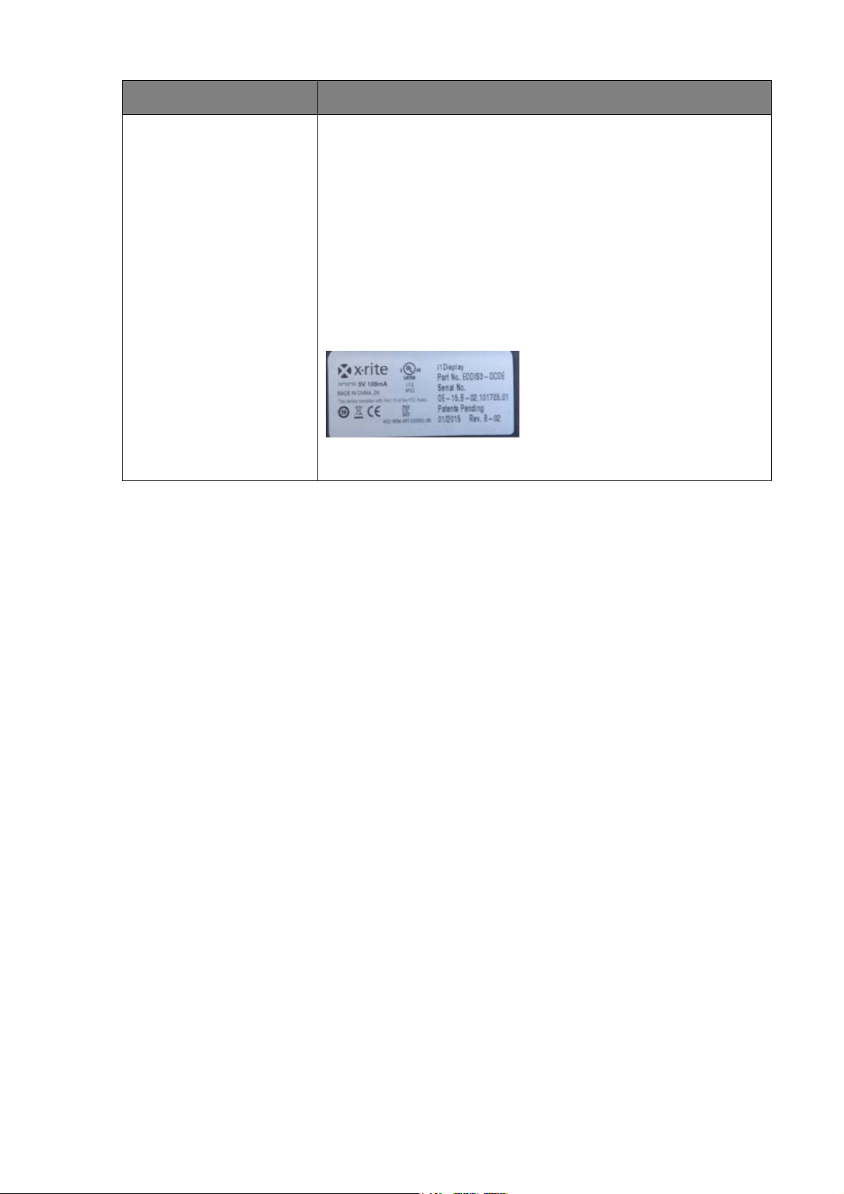
Color Meter x-rite, i1Display
Part Number:
• PL460/PH460/PL550/PH550: EODIS3-OEM
• PL490/PL552/PL553/SL490/SL550/PH5501/PH5502/PL5502:
EODIS3-DCOE
Software Version:
• PL490/PL552/PL553/PH5501/PH5502/PL5502: v.P.1.0.1
• SL490/SL550: v.S.1.0.1
PL490/PL552/PL553/SL490/SL550/PH5501/PH5502/PL5502
39 Video wall installation guide
Page 40
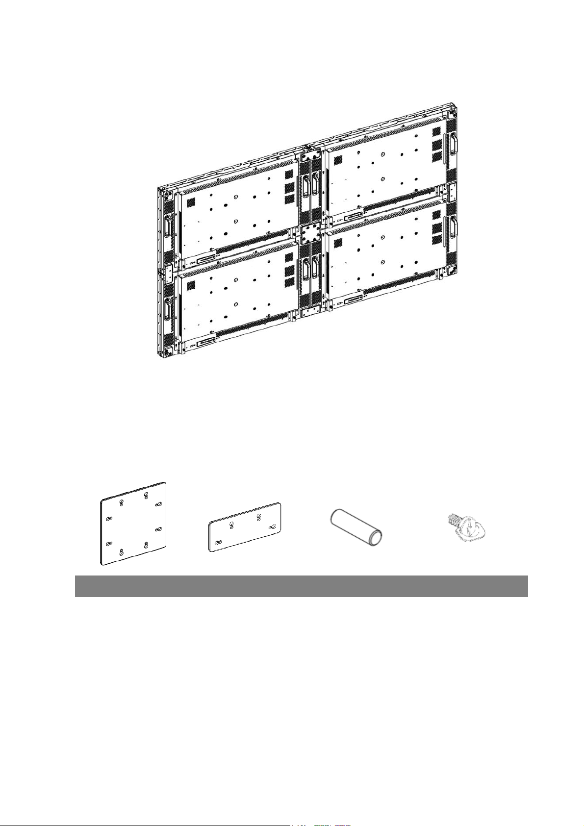
Operating Instructions of Edge Alignment Kit/Pin: PL490/PL552/PL553/PH5501/PH5502
Basic composition per set
1. Edge Alignment Kit-1: 1PCS
2. Edge Alignment Kit-2: 2PCS
3. Thumb Screw: 8PCS
4. Edge Alignment Pin: 2PCS
Edge Alignment Kit-1 Edge Alignment Kit-2 Edge Alignment Pin Thumb Screw
40 Video wall installation guide
Page 41

Function of Edge Alignment Kit/Pin
Without using edge alignment kit/pin.
Keep adjacent Displace at the same plane and uniform gap.
Installing Edge Alignment Kit
• Before install edge alignment kit, displays must be mounted to video wall frame correctly.
• Using “Thumb Screw” for easy installing.
• Using “Edge Alignment Kit-1” on adjacent four displays.
41 Video wall installation guide
Page 42

1. There are two loops of screw holes
(outer & inner), depend on the design of
each model. (Please check the user
manual for using loop information)
• Outer loop: Big screw holes for M6
screw.
• Inner loop: Small screw holes for M4
screw.
2.
Remark:
• M6 screw: for PL552/PL553/PH5501/
PH5502
• M4 screw: for PL490
• Using “Edge Alignment Kit-2” on adjacent two displays.
1. There are two loops of screw holes (outer
& inner), depend on the design of each
model. (Please check the user manual for
using loop information)
• Outer loop: Big screw holes for M6
screw.
• Inner loop: Small screw holes for M4
screw.
2. Remark:
M6 screw: for PL552/PL553/PH5501/
PH5502
42 Video wall installation guide
Page 43

Installing Edge Alignment Pin
• During mounting displays to video wall frame, using “Edge Alignment Pin” to secure the
flatness of adjacent displays.
• Don’t let edge alignment pin to touch the side surface of panel, panel will damage due to
incorrect installation.
• Using “Edge Alignment Pin” on adjacent displays.
There are 8 holes on the four corners of displays designed for plug-in the edge alignment pin.
43 Video wall installation guide
Page 44
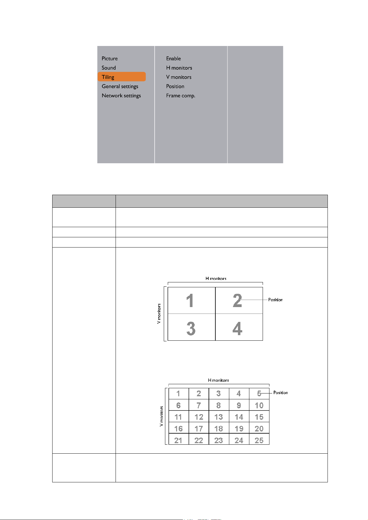
Tiling: PL490/PL552/PL553/PH5501/PH5502
With this function you can create a single large-screen matrix (video wall) that consists of up to
225 sets of this display (up to 15-sets on the vertical and 15-sets on the horizontal sides).
Te r m Description/explanation
Enable Choose to On or Off the Tiling function. If On, the display will apply
the settings in H monitors, V monitors, Position, and Frame comp.
H monitors Adjust displays on the horizontal side.
V monitors Adjust displays on the vertical side.
Position Adjust the position of this display in the screen matrix.
Example: 2 x 2 screen matrix (4 displays)
H monitors = 2 displays, V monitors = 2 displays
Frame comp. Choose to turn the frame compensation function on or off. If
44 Video wall installation guide
Example: 5 x 5 screen matrix (25 displays)
H monitors = 5 displays, V monitors = 5 displays
selected On, the display will adjust the image to compensate for the
width of the display bezels in order to accurately display the image.
Page 45

Setting the display position for special video wall layout
If a special layout is requested, you will need an additional software and device (purchased
separately) for advanced settings. Refer to the user manual of the purchased software for more
information.
45 Video wall installation guide
Page 46

Special signage installation guide
Front Side Back Side
Remote control
sensor
The barcode
is near the
front side.
D series Full HD 55-inch dual-side display
This guide provides additional information about how to install D series Full HD 55-inch
dual-side display. The dual-side display offers users access to information from both sides of the
panel. They can be hung from a ceiling, built into walls, or suspended.
Installation notice
• Identify the FRONT SIDE by finding the barcode. The barcode is near the front side.
• To make the input source work, the front side should always be connected FIRST before the
back side.
Playing the display
1. Always set the front side the display 1 and the back side the display 2.
2. There are two ports for media players. Try the other side of the display if the player
doesn’t start.
3. When using a computer, set the display to extension mode.
4. You need two different player software to have both sides of the display work at the same
time (e.g.,Windows Media Player and RealOne Player). Each side needs a different player.
46 Special signage installation guide
Page 47

Connecting HDMI cables and connectors
HDMI
HDMI
Back side Front side
Power box
AC in/switch
Plug two HDMI cables into the cabinet, and ensure that all cable plugs are firmly fitted into the
jacks.The main signal input source is HDMI 1. Make sure HDMI 1 is well connected before
connecting HDMI 2.
Connecting the power cord
Plug in the power cable and turn on the AC power switch.
47 Special signage installation guide
Page 48

Connecting the cables
If the display doesn’t work, unplug and re-plug the cables. Make sure the cables are plug-in
HORIZONTALLY and COMPLETELY.
48 Special signage installation guide
Page 49

Mounting installation
For DH551F, three mounting options are available: Ceiling Mount on page 49, U-Mount on page
54, and H-mount on page 58.
Ceiling Mount
Tools needed
Power drill Drill head Hammer Wrench 12mm
Allen wrench 5mm/
6mm
Phillips Pencil
Secure bracket to ceiling
1. Identify types of the target ceiling: Concrete or wood.
DO NOT secure the bracket to any decorative post or plasterboard for wood ceiling.
2. Drill holes of diameter 10mm and depth 55mm in concrete ceiling with power drill. Please
select expansion screws according to types of the ceiling. The expansion screws (B) come
with your product are designed for cement wall only. Screws for wood ceiling installation
shall feature adequate strength and validated by qualified technicians.
3. Hammer the expansion screws (M8xL60) (B) in the holes drilled earlier and tighten their
nuts.
49 Mounting installation
Page 50

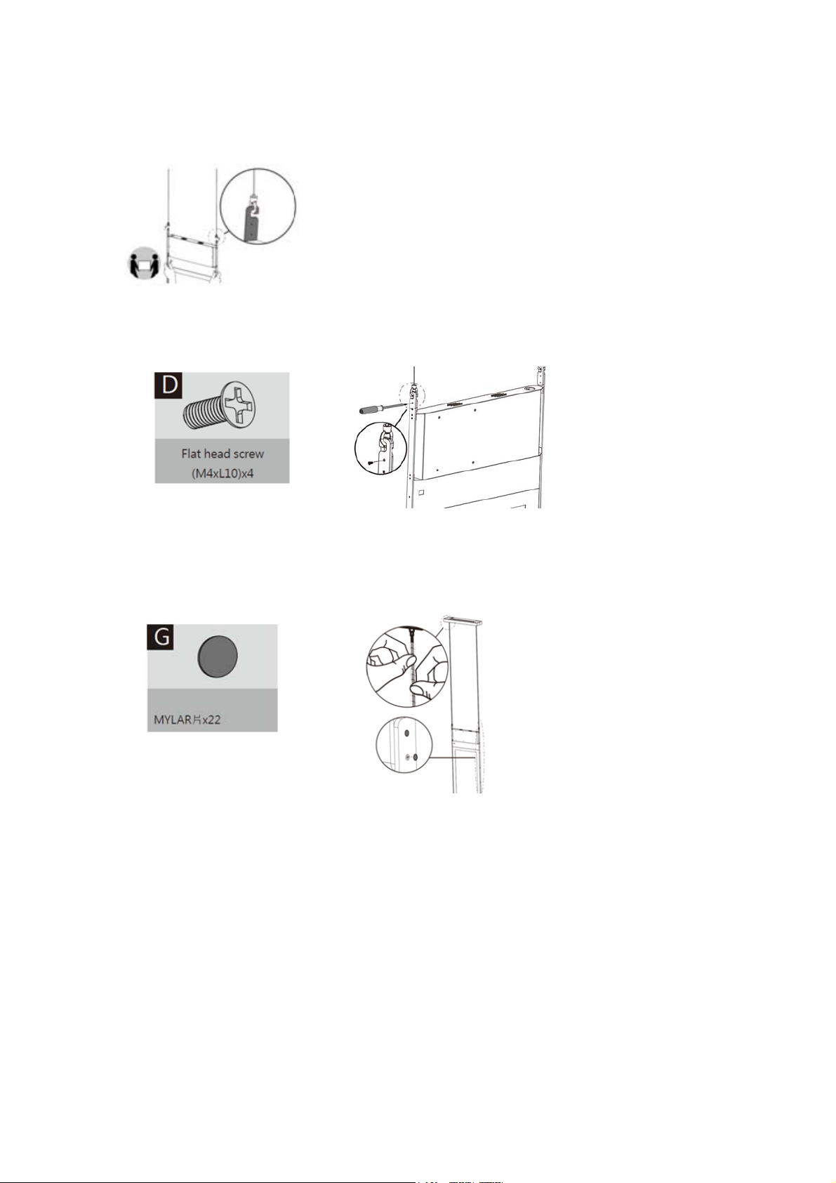
4. Remove the flat head screws (M3xL8) (C) with a Phillips screwdriver before pulling open
the plastic cover to the left and right.
5. Remove the spring washer and nut from the expansion screw and secure the bracket (A)
to the ceiling.
Places washers in sequence as shown below when securing the bracket to ceiling: Bracket (A)=> spring washer
=> nut
Install panel display to the bracket
Secure the display frame (E) to the display with the included flat head screws (M4xL10) (D) by a
Phillips screwdriver.
Secure device box to the bracket
1. Remove flat head screws (M3xL8) (C) with a Phillips screwdriver before removing the front
cover of the device box (F).
2. Secure the display box (F) to the display with the included flat head screws (M3xL8) (C) by
a Phillips screwdriver.
50 Mounting installation
Page 51

3. Lead cables out of outlet at bottom of device box for cabling.
4. Secure the front cover of the device box (F) to the later with the included flat head screws
(M3xL8) (C) by a Phillips screwdriver.
Adjust cable length
1. Leave appropriate cable length by winding the excessive section around the cable slot.
2. Replace the plastic covers to the left and right of the bracket before securing them with
the included flat head screws (M3xL8) (C) by a Phillips screwdriver.
51 Mounting installation
Page 52
Secure panel display to the bracket
1. Secure panel display to the bracket.
2. Secure the bracket to the panel display with the included flat head screws (M4xL10) (D) by
a Phillips screwdriver.
Protect with spiral wraps
Shield cables with spiral wraps.
Notice
1. Always set the front side the display 1 and the back side the display 2.
2. When using a computer, set the display to extension mode.
3. You need two different player software to have both sides of the display work at the same
time (e.g.,Windows Media Player and RealOne Player). Each side needs a different player.
4. Due to the size and weight of this display, it is recommended to move it with at least two
persons.
5. Power function of the remote controller works only when pointing to the front side of the
display; the other functions work at either side.
52 Mounting installation
Page 53

6. When turning off the display by disconnecting the power cable or DC power cord, wait
for 6 seconds before reconnecting the power cable or DC power cord for normal
operation.To protect your display from possible damage, do not put excessive pressure on
the display.
7. Don’t block the ventilation holes on the power box. It is prohibited to turn the ventilation
hole of Power Box upside down. It is prohibited to place tilt.
8. Ensure the use of an approved power cord provided by BenQ at all times. If your power
cord is missing, please contact your local service center.
9. Provide an earthing connection before the mains plug is connected to the mains. And,
when disconnecting the earthing connection, be sure to disconnect after pulling out the
mains plug from the mains.
10. Unplug the display if you are not going to use it for an extensive period of time.
11. Unplug the display if you need to clean it with a slightly damp cloth. The screen may be
wiped with a dry cloth when the power is off. However, never use organic solvent, such as,
alcohol, or ammonia-based liquids to clean your display.
12. If a foreign substance or water gets in your display, turn the power off immediately and
disconnect the power cord. Then remove the foreign substance or water.
13. Don’t store or use the display in locations exposed to heat, direct sunlight, or extreme
cold.
14. > 4.5m height is recommended, otherwise will be crowded.
15. Drawing of Ceiling Mount
53 Mounting installation
Page 54

U-Mount
To o l s n e e d e d
Power drill Drill head Hammer
Phillips screwdriver Pencil
Pre-action: secure bracket to a wall
1. Please identify the type of the target wall: Concrete or wood.
2. Please drill holes of diameter 10mm and depth 55mm in concrete walls with power drill at
locations you have marked earlier. Please select screws according to the type of the wall.
The expansion screws (B) that come with your product are designed for cement walls only.
Screws for wood wall installation shall feature adequate strength and be validated by
qualified technicians.
3. Hammer the expansion screws (M8xL60) (B) in the holes drilled earlier and tighten their
nuts.
• DO NOT secure the bracket to any decorative post or plasterboard for wood walls.
• Before drill the hole, use Pipe TOP and BOT to mark hole location on center line by pencil.
54 Mounting installation
Page 55

Installation steps
Step 1: Threading the cables through Pipe TOP and Frame
1. Shielding two power cables and also 2 HDMI cables
2. Threading the HDMI & Power cables through 2 Pipe TOPs (mark blue)
3. Threading the cables through the frame (mark orange)
Step 2: Set-up the display for installation
1. Putting the display front side up
2. Removing I/O covers at the sides
3. Removing the downside cover
55 Mounting installation
Page 56

Step 3: Connecting the Power cables & HDMI cable with double sided panel
1. Connecting the Power cables
2. Connecting the HDMI cables
3. Screwing the downside cover back
Step 4: Fixing the double sided display with Frame
1. Putting the double sided display into the Frame
2. Then, fixing them by screws
56 Mounting installation
Page 57

Step 5: Installing both Bracket L and Bracket corner on the frame at four corners
1. Installing Bracket L
2. Installing Bracket corner
3. Repeating the same actions at four corners
Step 6: Assemble Pipe TOP and Pipe BOT
1. Assemble Pipe TOP and Pipe BOT
2. Fix 4 Cover plates
57 Mounting installation
Page 58

H-mount
For tools needed, pre-action, and installation steps 1-5 of H-mount, please refer to U-Mount on
page 54. For steps 6-7 of H-mount, please read the following.
Step 6: Assemble Pipe TOP and Pipe BOT
1. Assemble Pipe TOP and Pipe BOT
2. Fix 4 Cover plates
Step 7: Mounting Pipe TOP and Pipe BOT with ceiling and ground
58 Mounting installation
Page 59
Digital Signage Bar-Type Series
The bar type display panel is a long structured design panel. Designed with a slim form factor,
the display panel can be used in small or large spaces to display everyday information.
Installation notice
• When the display is connected to the PCs or laptop, it is at its native resolution.
Model Native Resolution (pixels)
BH2401/BH2401T 1920 x 190
BH3501/BH3501T 1920 x 130
BH280/BH281/BH2801/BH2801N 1920 x 360
BH380 1920 x 545
BH3801/BH3801N/BH3801D 1920 x 600
• Set the display to the projector mode. The picture will be displayed with full screen.
• If the aspect ratio of the picture is the same as that of the display, the picture can be fully
shown without distortion.
Position Description
Top The window is positioned to the top 1/3 of the screen.
Bottom The window is positioned to the bottom 1/3 of the screen.
Middle The window is positioned to the middle 1/3 of the screen.
Zoom Out The full screen is compressed into the window.
Zoom In • When the window is positioned to the top 1/3 of the screen,
the input image zooms in 3%.
• When the image is on the top and does not fill the screen, you
can choose this position to present the best effect.
Adjusting the OSD setting: For BH280/BH281/BH380
The resolution can be adjusted to 1920x1080. You can make the following display effects by
adjusting the OSD setting.
• If the input source is not1920x1080, only Zoom Out can be selected.
• Frequency : Frequency narrows or widens the screen.
59 Digital Signage Bar-Type Series
Page 60

BH series HDMI connetion (EXCEPT BH280/BH281/BH380)
HDMI in connection
Connect the BH series with PCs or laptop, go to Windows Setting > Display and choose
the BH series as an extension display. In the following methods, we use BH3801 (1920 x 600) as
an example.
BH2401/BH3501 are only applicable with method 2.
Method 1: Content is customized to the corresponding resolution 1920 x 600.
1. In Windows Setting > Display > Advanced display setting, select the BH3801 and
choose 1920 x 600 as resolution setting.
2. On BH3801, users can either choose Full or 1:1 in Display > Zoom mode.
If the 1920 x 600 content is not allocated at the right ratio, it is caused by frequently switching
between resolutions, and the setting in the video graphics card goes wrong.
1. Please go to Windows Setting > Display > Advanced display setting > Display
adapter properties.
60 Digital Signage Bar-Type Series
Page 61

2. Change the screen refresh rate to 60Hz in Monitor section. The content should be
allocated at the right ratio.
Method 2: Content is in the upper section of 1920 x 1080
1. In Windows Setting > Display > Advanced display setting, select the BH3801 and
choose 1920 x 1080 as resolution setting.
2. On BH3801, choose 1:1 in Display > Zoom mode to correctly display the content.
3. To proceed further Windows control, choose Full in Display > Zoom mode to gain full
screen access on BH3801.
61 Digital Signage Bar-Type Series
Page 62

Troubleshooting
Audio cable
DVD player/VCR
Component
video cable
Audio cable
DVD player/VCR
AV cableS-Video cable
Connections
The input and output ports illustrated here are for your reference only. The availability and
layout of all ports may vary by model.
How to connect a DVD player to the display?
You can use either Component or S-Video for connection.
DVI-OUT
HDMI-2
DVI-IN
HDMI-1
VGAOUT
VGAIN
DVI-OUT
HDMI-2
DVI-IN
HDMI-1
VGAOUT
VGAIN
62 Troubleshooting
Page 63

How to connect a computer to the display?
D-Sub (15-pin) cable Audio cable
Computer
Analog signal
DVI-OUT
DVI-IN
HDMI-2
HDMI-1
VGAOUT
VGAIN
Audio cable
Computer
DVI-D cable
HDMI
cable
DisplayPort cable
Digital signal
You can connect a computer to the display through D-Sub (VGA)/DVI/HDMI/VGA as desired.
DVI-OUT
HDMI-2
DVI-IN
HDMI-1
VGAOUT
VGAIN
63 Troubleshooting
Page 64

How to connect to external speakers?
External speakers
While the display is turned off, connect external speakers to the SPEAKERS (R/L) jacks on
the display via an appropriate audio cable. And then turn on the display.
DVI-OUT
HDMI-2
DVI-IN
HDMI-1
VGAOUT
VGAIN
64 Troubleshooting
Page 65

Picture/video
No picture is displayed.
Possible causes Possible solutions
The power cord is not connected. Re-connect the power cord.
The main power switch on the
back of the displayed is not
switched on.
The selected input is not
connected.
The display is in Standby mode
when the input source is D-Sub
(VGA).
Incorrect cable connection.
The main board could be
damaged.
Make sure the power switch is switched on.
Depending on the selected input, connect the display with
the input source using the appropriate cable(s).
Check the cable connection. See the user manual for
details.
Press any of the control panel (keypad) buttons and check
if the OSD menu could be displayed. If yes, the problem lies
somewhere else.
Try with another display resolution or another graphic card
(GPU).
Restore the display to the default factory settings.
Contact the BenQ authorized service partner for
replacement.
Screen interference is observed or noise is heard.
Possible causes Possible solutions
This could be caused by other
appliances, traffic, or fluorescent
lights in the surroundings.
Poor quality cable is used for
signal input.
The image has a faulty coloration.
Possible causes Possible solutions
The video cable is not connected
properly.
• Go to Picture > Noise Reduction.
• Move the display to another location to see if the
interference is reduced.
Try with another video cable.
Make sure the video cable is connected firmly to the
display.
65 Troubleshooting
Page 66

The picture is distorted with strange patterns.
Possible causes Possible solutions
The video cable is not connected
properly.
The image format is not
supported by your display.
Make sure the video cable is connected firmly to the
display.
Check the specifications to verify the display’s supported
formats.
The picture does not fill up the full screen when the input source is D-Sub (VGA).
Possible causes Possible solutions
Go to Screen > Aspect > Wide Zoom or Zoom to
adjust the display’s geometry and time frequency
The picture is not properly
zoomed.
parameters. Refer to the user manual for more
information on the menu options.
Note the picture may be distorted or stretched if fitted to
the screen.
You are running the display at its native resolution, but the image is still distorted.
Possible causes Possible solutions
Images from different input
sources may appear distorted or
stretched on the display running at
Go to Screen > Aspect to set a proper aspect ratio for
the input source.
its native resolution.
Sound can be heard but no image is displayed.
Possible causes Possible solutions
The video cable is not connected
properly.
Make sure the video cable is connected firmly to the
display.
(If the input is HDMI)
Try with another HDMI cable.
Poor cable quality.
66 Troubleshooting
Page 67

The picture unstable, unfocused, or swimming.
• Make sure the video cable is connected firmly to the display.
• Go to Screen > Adjust Screen to focus and adjust the display. Try with Auto
Adjustment first to adjust the settings automatically. If it does not help, you can make
adjustment manually. Once the display mode is changed, you may need to adjust the screen
again.
• Check if a supported timing is set. On your display, press INFO on the remote control to
find out the current resolution and timing. Alternatively, you can check the information from
your computer. The way to check the timing may differ by operating system. Refer to the
help document of your operating system for details.
• Try with another video cable.
Does my display support PIP (Picture in Picture) function?
Yes, but the availability of PIP function also depends on the video sources. Refer to
Supported PAP input signal combination in the user manual of the purchased model
for details.
The PIP function will be disabled if the video wall or the touch function is in use.
The picture is not displayed in the center of the screen when the input source is D-Sub (VGA).
Go to Screen > Adjust Screen to make adjustment.
For advanced setting, change the setting under H. Position and V. P os it i on . See the user
manual of the purchased model for more information.
In H. Position, press /+ on the control panel to move the picture to the right; press /- to
move the picture to the left.
In V. Po sit io n , press /+ on the control panel to move the picture up; press /- to move the
picture down.
What are the supported resolutions of my display?
The supported resolutions may differ by model. Refer to Supported input signal
resolution in the user manual of the purchased model for details.
What is the recommended refresh rate?
The recommended refresh rate for your display is 60 Hz.
67 Troubleshooting
Page 68

The display flickers when I launch or close a program.
• The signal may not be stable. Check the cable connection or try with another video cable.
• The panel backlight may be unstable. Contact the BenQ authorized service partner for
replacement.
Audio
The image is displayed but no sound is heard.
Possible causes Possible solutions
Your graphic card driver is not
installed or updated.
The audio cable is loose.
Not external speakers are
connected.
The audio output device is not
consistent with the display setting.
Either the display’s or PC’s
Speaker has been muted.
The main board could be
damaged.
(If the signal source is HDMI/DP)
The Speakers in your OS is not
set properly.
Your display’s audio input is not
set to DisplayPort or HDMI.
Update the driver through Windows Update (for
Windows Operating Systems) or the graphic card’s
manufacturer.
Power off the display and re-connect the audio cable.
Power on the display again.
Connect external speakers to the display and adjust the
volume appropriately.
Make sure the setting in Speaker on your display is the
same with the audio output device.
Disable mute by pressing the MUTE button on the remote
control.
Contact the BenQ authorized service partner for
replacement.
Set DisplayPort or HDMI as the default speaker in your
operating system and launch the media player again.
Set the Audio Source of your display to DisplayPort or
HDMI.
Remote control
The remote control does not work.
Possible causes Possible solutions
The remote control does not
work.
The battery drained out. Replace with a new battery.
The remote control is damaged. Try with a new remote control.
The IR receiver could be damaged.
It is out of the IR remote control
range.
68 Troubleshooting
Refer to Notes on using the remote control on page 8.
Check if the LED indicator of the IR receiver lights red or
does not light up. If so, contact the BenQ authorized
service partner for replacement.
Check the specifications and adjust the distance between
the remote control and the display.
Page 69

Touch function (selected models only)
The touch function does not work.
Possible causes Possible solutions
The touch function is not
supported by your OS.
The touch driver is not installed.
No stable or enough power
supplied for your computer.
The touch sensor is covered by
dust.
Check the user manual for the supported operating
systems.
Visit the BenQ local website for the appropriate driver
files.
The touch module needs to get enough power supply from
your computer to work well.
• Try with another computer.
• Disconnect all the other USB peripherals.
• Add a power hub that helps supply more power to your
computer.
Clean the touch sensor properly.
1. Be sure to turn off the display and unplug the power
cord before you clean the screen.
2. Remove dust or dirt from the screen and the infrared
plastic filter periodically. It is suggested using a small
amount of alcohol to clean the infrared plastic filter.
3. Moisten a clean, soft, lint-free cloth with a neutral
detergent and then clean the touch screen.
Use a neutral detergent to clean the touch screen. Avoid using
detergents with erosive substance, such as banana oil or
ammonia. To avoid damage to the screen, never use any type of
abrasive materials to wipe the screen.
• Check if the USB cable has been connected properly, or
try with another USB cable.
• Connect the computer with your display only; remove
Poor USB connection.
other USB peripherals.
• Connect a computer with the display through USB cable
directly without any extension (e.g. faceplate or USB
extension cable) to ensure the touch function works.
The drawing is not displayed correctly (e.g., double lines, spiking, etc.).
Possible causes Possible solutions
An inappropriate stylus
(particularly too thin) is used.
Try with a thicker stylus. Refer to the following stylus
specifications.
69 Troubleshooting
Page 70

Touch vendor Stylus dimensions Accuracy Applicable models
NextWindow < 47" diameter: Ø6,
± 3mm ≤ 55"
T420/T650/TL550/TL650/
RP650/RP650+
65": Ø9
5mm > 55"
Nexio 42"/45"/55": Ø8 ± 2.5mm IL420/IL460
IRTouch 65" diameter: Ø8 ± 1.5mm in center,
IL650/RM650
± 2.5mm near
border
CVTTouch 6mm for single touch
8mm for multi touch
+/-2.0mm (Over
90% of touchable
area)
RP551/RP651/RP700/RP701/
RP552/RP652/RP702/RP705/
RP790/RP840G/RP553K/
RP653K/RP654K/RP704K/
RP750K/RP860K/RP860S/
IL430/IL490/IL550
IST U 3mm for single touch
6mm for multi touch
IST X 2mm for single touch
5mm for multi touch
+/-1.0mm (over
90% of touchable
area)
+/-1.0mm (over
90% of touchable
area)
RM5501K/RM6501K/
RM7501K/RM8601K
RP6501K/RP7501K/RP8601/
RM5502K/RM6502K/
RM7502K/RM8602K
CVTE P-Cap 6mm for passive
2mm for active
IRTouch HE
>2mm +/- 1mm (over 90%
series
IRTouch MD
>3mm +/- 1mm (over 90%
series
Strong light reflection.
The interactive software
(purchased and installed separately
by user) may not be compatible
with the system.
Poor USB connection.
+/- 1.5mm (over
CP6501K/CP8601K
90% of touchable
area)
RP6502, RP7502, RP8602
of touchable area)
RP6502, RP7502, RP8602
of touchable area)
Re-direct the lights or move the display to another location
to avoid unwanted reflections from light sources.
• Try with a different version of interactive software.
• Try with the basic drawing program pre-installed on your
computer. (e.g. Microsoft Paint in Windows).
Check if the USB cable has been connected properly, or
try with another USB cable.
70 Troubleshooting
Page 71

OSD menu/control panel/power button
The OSD menu does not work.
Possible causes Possible solutions
The control panel (keypad) could
be damaged.
Contact the BenQ authorized service partner for
replacement.
The keypad or IR (remote control) does not work.
The keypad or IR could be locked. Please check the following to unlock it.
Model/Function
RP654K, RP704K,
RP750K, RP860K
Keypad
Lock/unlock
1. Press green
button on
the remote
control.
IR (remote
control)
lock/unlock
OSD setting Press red
Lock/unlock
keypad and
touch
1. The Key Lock and
button on the
remote
control.
RP552, RP552H,
RP653, RP703,
RP840G
2. OSD setting
OSD setting OSD setting Press red
button on the
remote
2. Lock/unlock
control.
RP553K, RP653K,
ST430K, ST550K,
ST650K, RM5501K,
RM6501K,
1. Press and
hold [CH+]
button.
2. OSD setting
1. Press and
hold [CH+]
button.
2. OSD setting
RM7501K,
RM8601K
IL430, IL490, IL550,
SL490, SL550
1. Press both +
and
of
remote control buttons
and hold for
more than 3
seconds.
2. OSD setting
1. Lock - OSD
setting
2. Unlock press and
hold
[i]INFO
button on
the remote
control for
6 seconds.
PL490, PL552,
PL553, PH5501,
PH5502
1. Press
and 1998 on
the remote
control.
1. Press
and 1998 on
the remote
control.
Remark
IR Lock functions
cannot be enabled
at the same time.
touch - yellow
button on remote
control.
2. OSD setting
2. OSD setting
71 Troubleshooting
Page 72

ST4301K, ST5501K,
ST6501K
RP6501K,
RP7501K, RP8601K
RM5502K,
RM6502K,
RM7502K,
RM8602K,
CP6501K,
CP8601K
SL4302K, SL5502K,
SL6502K, SL7502K,
SL8602K, SL9802K
BH2401, BH2401T,
BH3501, BH3501T,
BH2801, BH2801N,
BH3801, BH3801N,
BH3801D, ST4302,
ST5502, ST6502,
ST7502, ST8602
RE6501, RE7501,
RE8601, RP6502,
RP7502, RP8602
OSD setting OSD setting Key lock and IR lock
functions cannot be
enabled at the same
time.
OSD setting OSD setting Unlock only:
Lock/unlock touch OSD setting
1. MENU
[V+] [V+]
[V-] (before
FW
v1.0.0.8)
2. Press
on the
remote
control for
five
seconds
(after FW
v1.0.0.8).
OSD setting OSD setting Unlock only:
Lock/unlock touch OSD setting
Press on
the remote
control for five
seconds.
OSD setting OSD setting Key lock and IR lock
functions can be
enabled at the same
time.
1. OSD setting
2. Vol+ up left
down right
OSD setting OSD setting
1. OSD setting
2. Vol+ up left
down right
1. Press
on the
Lock/unlock touch OSD setting
remote
control for
five seconds.
72 Troubleshooting
2. Press
on the
keypad for
five
seconds.
Page 73

Some of the OSD menu options are grayed out. When are those items available for setup?
Available menu options may vary depending on the input sources, functions and settings.
The power button does not respond.
Possible causes Possible solutions
Power cord is not connected
properly.
The control panel could be
damaged.
Re-connect the power cord.
Contact the BenQ authorized service partner for
replacement.
LED indicators
The LED indicator of control panel (keypad) or IR receiver flashes red quickly.
Possible causes Possible solutions
The main board could be
damaged.
Contact the BenQ authorized service partner for
replacement.
Power
The display can’t be powered on.
Possible causes Possible solutions
No power is supplied to the
display.
One of the key components of the
display could be damaged.
• Re-connect the power cord.
• Check if the power outlet works.
Contact the BenQ authorized service partner for
replacement.
73 Troubleshooting
Page 74

System: PL460/PH460/PL550/PH550
How to restore the factory default settings?
Go to Setting > All Reset. All except the settings under the Picture and Sound menus
will be restored back to the factory default settings.
To reset all settings in Picture, go to Picture > Reset.
To reset all settings in Sound, go to Sound > Reset.
How to set time and date?
Go to Setting > Schedule.
Press the control panel buttons to adjust the system clock. Refer to the user manual for more
information.
What to do if the Out of Range message is prompted?
The resolution currently set is not supported. Refer to Supported input signal
resolution in the user manual of the purchased model for the supported timings.
What are the supported resolutions of my display?
The supported resolutions may differ by model. Refer to Supported input signal
resolution in the user manual of the purchased model for details.
Vapor or mist is observed inside the glass.
Under certain circumstances, condensation may occur on the inner side of the cover glass, it's
a natural phenomenon and will not affect the operation of the display. This condensation will
usually disappear after around 2 hours of normal operation.
How to check the version of system software?
Go to Setting > Information > Software Version to find out the software version.
74 Troubleshooting
Page 75

Troubleshooting: PL490/PL552/PL553/PH5501/PH5502
Symptom Possible Cause Remedy
No picture is displayed. 1. The power cord is discon-
nected.
2. The main power switch on the
back of the display is not
switched on.
3. The selected input has no
connection.
4. The display is in standby mode.
Interference displayed
on the display or
Caused by surrounding electrical
appliances or fluorescent lights.
audible noise is heard.
Color is abnormal. The signal cable is not connected
properly.
Picture is distorted
with abnormal
patterns.
1. The signal cable is not connected properly.
2. The input signal is beyond the
capabilities of the display.
1. Plug in the power cord.
2. Make sure the power
switch is switched on.
3. Connect a signal
connection to the display.
Move the display to another
location to see is the
interference is reduced.
Make sure that the signal cable
is attached firmly to the back
of the display.
1. Make sure that the signal
cable is attached firmly.
2. Check the video signal
source to see if it is
beyond the range of the
display. Please verify its
specifications with this
display’s specification
section.
Display image doesn’t
fill up the full size of
the screen.
Can hear sound, but
no picture.
Can see picture but no
sound is heard.
1. The zoom mode is not set correctly.
2. Scan Mode may be set
incorrectly to underscan.
3. If the image exceeds the screen
size, Scan Mode may need to
be set to Underscan.
Improperly connected source
signal
cable.
1. Improperly connected source
signal cable.
2. Volume is turned all the way
down.
3. Mute is turned on.
4. No external speaker
connected.
Use the Zoom mode or
Custom zoom function in the
Screen menu to fine tune
display geometry and time
frequency parameter.
Make sure that both video
inputs and sound inputs are
correctly connected.
1. Make sure that both video
inputs and sound inputs are
correctly connected.
2. Press or button to
hear sound.
3. Switch MUTE off by using
the button.
4. Connect external speakers
and adjust the volume to a
suitable level.
75 Troubleshooting
Page 76

Symptom Possible Cause Remedy
Some picture elements
do not light up.
After-Images can still
be seen on the display
after the display is
powered off. (Examples
of still pictures include
logos, video games,
computer images, and
images displayed in 4:3
normal mode)
Some pixels of the display may not
turn on.
A still picture is displayed for an
over extended period of time.
This display is manufactured
using an extremely high level of
precision technology: however,
sometimes some pixels of the
display may not display. This is
not a malfunction.
Do not allow a still image to be
displayed for an extended
period of time as this can
cause a permanent after-image
to remain on the display.
76 Troubleshooting
Page 77

Wall mounting/video wall
Is wall mounting kit available?
The wall mounting kit should be purchased separately, though the screws needed for wall
mounting are included in the product.
The mounting interface should comply with the UL1678 standard in North America. The mounting means
should be strong enough to bear the weight of the display.
What to do if colors among all displays do not match?
Re-connect a cable from one computer to another to check if it is the video output that went
wrong.
Re-connect a cable from one display to another to check if it is the display that went wrong.
If it is the video input that went wrong, check the following:
• Make sure that the signal is output from the same source (e.g. D-Sub).
• It is recommended to use cables of equal length for connection.
• Do not use more than 2 splitters to produce video wall.
• If the total fitment width of the video wall is more than 10 meters, use an amplifier or
resistance wire avoid signal attenuation during transmission.
• If the signal came from more than one computer, make sure that all computers use the same
type of graphic card.
If it is the display that went wrong, check the following:
• Check if all the settings of the following options in the Picture menu on all displays are
identical.
- Picture Mode (Standard mode is recommended)
- Backlight
- Contrast
- Brightness
- Chroma
- Phase
- Sharpness
- Color Temp.
• Check if the settings of Adaptive Contrast and Ambient Light Sensor in Setting >
Advanced on all displays are identical.
• Adjust the colors by calibration tools (purchased separately).
I, _____________________ hereby confirm that I have read this document and understand
its content.
77 Troubleshooting
Page 78

Preventing afterimage burn-in
If you leave the screen fixed on a stationary image for an extended period of time, afterimage
burn-in or defective pixels may occur. Power-saving mode or a dynamic screen saver should be
activated in case you will not be using the product for an extended period of time.
When the LCD panel is not operating normally, afterimage burn-in may occur.
Normal operation means a consecutively changing video pattern. If the LCD panel shows a
fixed pattern for an extended period of time, a little voltage difference may occur between the
electrodes in pixels controlling the liquid crystals.
The voltage difference between electrodes may increase with time. This can cause the liquid
crystals to get thinner. A previous image can stay on the screen as the pattern changes. To avoid
this situation, the compiled voltage difference should be diminished.
To avoid afterimage burn-in, turn off the power or set the PC or system to run a screen saver
when not in use. Warranty service may be restricted relying on the instruction guide.
Power saving mode
• After using the product for 12 hours, turn it off for 2 hours.
• Power saving mode may vary by models. Please refer to user manuals for more information.
• Use a recommended screen saver. A single-color or moving-image screen saver is the best.
Regular color change
• Switch between 2 colors every 30 minutes.
• Avoid mixing a text color and background color of contrasting brightness.
• Prevent using grey as it may cause afterimage burn-in.
• Prevent using colors of contrasting brightness, e.g., black and white.
Regular text color change
Use bright colors of similar brightness and regularly show a moving image along with a logo.
• Change text color and background color every 30 minutes.
• Show a moving image along with a logo for 60 seconds after using for 4 hours.
78 Preventing afterimage burn-in
Page 79
Appendix 1: Installation Checklists
Check the following one by one for a new installation. Contact the BenQ local customer
service center with the checking results if any severe damages is found before a new
installation.
Before installation
No. Check items
1. The Installation Handbook has been read through carefully.
2. • For certain models, there may be void labels or additional
packing tapes on the carton. Check whether the labels or tapes
are broken. If broken, take the photos and contact BenQ for
further assistance.
• If the unit is packed in the pallet, please identify where the unit
is placed in the pallet.
Checking
results
Ye s No
Location &
description
of problem
3. Check if the shock indicator (if available) on the carton has
changed its color from white to red.
4. Check if there is any serious damage to the carton, especially to
the edges and surface area.
5. Check if there is any serious scratches, marks or damages caused
by collision to the inner side of the carton.
6. Check if the cushions or PE bags are broken or distorted.
7. Check if there is any serious damage (i.e. scratches, cracks,
bends) to the bezel, metal frame, rear cover, and the accessories
8. Check if any accessory is missing.
9. Check if the panel is damaged (i.e. scratched or cracked).
10. Power on the display and check if the screen is normal.
79 Appendix 1: Installation Checklists
Page 80

After installation
No. Check items
1. Check if there is any damage to the panel (scratches or cracks) or
to the bezel (scratched or faded paint).
2. Check if all cables have been connected properly.
3. (For video wall) Check if all displays have been installed on a
(horizontal/vertical) level surface.
4. (For video wall) Check if there is enough space (0.5 mm as
recommended) between two displays.
5. Connect your video source (e.g. computer) and power on the
display to check if the screen is normal.
Checking
results
Ye s No
Location &
description
of problem
80 Appendix 1: Installation Checklists
Page 81

Warranty information
I, _____________________ hereby confirm that I have read this document and
checked the items mentioned above.
BenQ warranty does not cover the damages caused by improper installation, operation, or
storage of the product, including but not limited to the following:
1. Damages to the packaging or product after re-packing. This includes but not limited to the
color change of shock indicator (if available), serious scratches on the package, and/or broken cushions or PE bags. Please make sure to check the product and all the supplied items
once the original package is unsealed.
2. Panel bending and/or distorted corner(s) of panel caused by improper installation or
storage, or inappropriate way to move the display.
3. Scratches, cracks, faded paint, and/or other physical damages to the panel, bezel, metal
frame, rear cover, and accessories.
4. Abnormal display (lines, mura, or light leakage) caused by the collision or excessive force
during installation.
5. Missing accessories during installation.
6. Any damages or performance failure caused by not following the instructions in the
Installation Handbook.
7. LCD screens, like plasma (PDP) and conventional CRT (Cathode Ray Tube) screens, are
also susceptible to 'screen burn-in' or 'image retention' which can be found on the screen
as visible fixed lines and shades. To avoid such damage to the screen, avoid displaying still
images (like On-Screen Display menus, TV station logos, fixed/inactive text or icons) for
more than two hours. Change the aspect ratio from time to time. Fill the entire screen
with the image and eliminate the black bars whenever possible. Avoid displaying images in
4:3 aspect ratio over a long period of time, otherwise there may be visible burn marks on
the screen as two vertical lines.
• It is the sole responsibility of the user if problems (e.g. system failure) occurred due to non-factory installed
parts and/or non-original accessories.
• Under certain circumstances, condensation may occur on the inner side of the cover glass, it's a natural
phenomenon and will not affect the operation of the display. This condensation will usually disappear after
around 30 minutes of normal operation.
81 Appendix 1: Installation Checklists
Page 82

Appendix 2: Basic Troubleshooting Checklists for IFP & IL series
Dear Customer,
In order to avoid unnecessary delays and a volley of questions back and forth may we ask, kindly
fill in the form below. The more comprehensive information we have the faster our response
will be.
Part I: customer feedback form (customer information and description of problem)
Onsite contact person:
Phone number:
E-mail address:
Address of unit:
Model name:
Quantity on site: ______ unit(s).
Quantity affected: ______ unit(s).
Problem frequency: Constantly Intermittently After a while
Problem type: Touch Power Display Android/APP Other
Short problem description
Connections visible: HDMI
(Figure 1)
Question Ye s No
D-Sub (VGA)
(Figure 2)
USB
(Figure 3)
DVI
(Figure 4)
DisplayPort
(Figure 5)
Not
certain
Are the affected units connected to a faceplate (Figure 6)?
Are the cables passing though any wall or floor trunking?
Is the original USB cable (Figure 3) provided by BenQ
being used?
82 Appendix 2: Basic Troubleshooting Checklists for IFP
Page 83

Question Ye s No
Are there any extensions being used with the USB cable
(Figure 3)?
Are there any USB-powered hubs (Figure 7) being used?
Are there any USB-CAT5 converters (Figure 8) being
used?
Do you know what version of Smart Notebook Software
(if provided) is installed in your computer?
Please specify your computer operating system and
version.
Not
certain
What is the main device (video source) connected to the
display? Please specify the brand and the model name.
(Skip this question if no laptop is being used.)
If the video source is a laptop, is it plugged into a powered
wall socket?
What is the USB cable (Figure 3) length, including trunking
in wall?
What is the signal cable (HDMI, DVI, VGA, etc.) length,
including trunking in wall?
Who installed these units for you?
Please provide the installer's contact name & phone
number.
Are there any non-BenQ preloaded APP?
Please specify the name of APP which having the issue.
Desktop Laptop Other
_______ meters.
_______ meters.
Additional information
Provide photo/video link
83 Appendix 2: Basic Troubleshooting Checklists for IFP & IL
Page 84

Part II: problem resolving attempt & troubleshooting
The following checklist helps you identify the problem and resolve it quickly. In case a specific
problem occurs, refer to its related section and follow the check items to resolve the problem.
Contact the service provider if the problem cannot be resolved as instructed in this checklist.
Possible problems are:
• Power • Touchscreen • Intermittent touch signal loss
• Ghost touch • Flickering picture • Condensation
• Failed calibration • Add extender/repeater • Noise/interference
• Compatibility - Cannot
detect IFP/DS
Power
Try the following if the display cannot be powered up.
• Android/APPs • OTA
Check item
Check if
completed
Does the
problem still
exist?
Please try replace the power cord.
Check if the power cable has been properly connected.
Please try to connect the display to a different power outlet.
Make sure the power switch (usually located at the rear of the
display) is switched on.
Check the status of the power indicator – what color is it?
Touchscreen
Check item
Check if
completed
Ye s No
Does the
problem still
exist?
Please try with another USB cable (Figure 3).
84 Appendix 2: Basic Troubleshooting Checklists for IFP
Ye s No
Page 85

Check item
Please try with another USB port on the video source (e.g.
computer).
Please try to connect the display to another video source (e.g.
computer).
Please try to connect the display to the video source (e.g.
computer) directly without any extension/trunking/faceplate.
Try to un-install the Smart Notebook software (if provided), and
install an earlier version. Contact the service provider for an
earlier version if needed.
Try with Windows Paint (for Windows operating systems).
Try with a thicker touch pen (6 mm as recommended, Figure 9)
for drawing on the touchscreen.
Check if
completed
Does the
problem still
exist?
Ye s No
Use USB cable shorter than 5m or use extender if longer than
5m.
If the touch is not working only under Android, please connect to
the external device to confirm.
Intermittent touch signal loss
Check item
Please try with a different video source (e.g. computer).
Please try with a shorter USB cable (Figure 3).
Please try with another USB port on the video source (e.g.
computer).
Please try use a USB-powered hub (Figure 7) to connect the
video source (e.g. computer) and your display.
Check if
completed
Does the
problem still
exist?
Ye s No
Use USB cable shorter than 5m or use extender if longer than
5m.
85 Appendix 2: Basic Troubleshooting Checklists for IFP & IL
Page 86

Ghost touch
Check item
Moisten a clean, soft, lint-free cloth with a neutral detergent and
then clean the frame and the touchscreen carefully.
Please try to draw the lines in Windows Paint (for Windows
operating systems).
Make sure that only the tip of the touch pen touches the screen.
Keep your hand away from the touchscreen, as the detectors may
detect your hand even it does not touch the screen surface.
Check if
completed
Does the
problem still
exist?
Ye s No
Flickering picture
Check item
Please try with another video signal cable (HDMI/D-Sub/DVI/
DP).
Please try with another video input. For example, change from
D-Sub to HDMI or DVI.
Please try with another video source. For example, change a
computer.
Check if all cables are connected properly.
Un-plug the USB cable (if connected, Figure 3).
Please try with a D-Sub cable with a thicker EMI core (ferrite
filter, Figure 10), which suppresses more high frequency noise.
Check if
completed
Does the
problem still
exist?
Ye s No
Please try to connect the display to a different power outlet.
86 Appendix 2: Basic Troubleshooting Checklists for IFP
Page 87

Does the
problem still
exist?
Ye s No
Check item
Check the timing using is supported by the device.
Check if
completed
Condensation
Condensation on the inner side of the glass is a natural phenomenon when the temperature
and humidity of the air change quickly. Condensation may occur if the display is powered on
after not being used for a long time, or if the heating system of the room is switched on. And it
may last for hours.
Does the
problem still
exist?
Ye s No
Check item
Keep the display powered on for at least 24 hours.
Check if
completed
Keep the display away from the window.
Failed calibration
Check item
Please try with the built-in calibration tool on the Windows
operating system.
Contact the service provider to see if a calibration software is
available.
Add extender/repeater
Check item
Check if
completed
Check if
completed
Does the
problem still
exist?
Ye s No
Does the
problem still
exist?
If the touch is not working, please add a USB hub/extender.
If there is no display, please add the display port repeater
(ex.HDMI repeater).
Ye s No
87 Appendix 2: Basic Troubleshooting Checklists for IFP & IL
Page 88

Check item
Try with shorter cables (shorter than 3M for display cable/1.8M
for touch USB cable). If the problem is solved, please try to add
the repeater.
Noise/interference
Check item
Unplug the USB cable.
If unplugging the USB cable can solve the problem, please use the
digital signal (ex. HDMI or DVI) with the touch USB cable.
Check if
completed
Check if
completed
Does the
problem still
exist?
Ye s No
Does the
problem still
exist?
Ye s No
Try to use another AC socket.
Try to use the AC jack without ground.
Compatibility - Cannot detect IFP/DS
Check item
Try another PC/NB (different brand/model).
Try to add the repeater to boost the signal.
Android/APPs
Check item
Check if
completed
Check if
completed
Does the
problem still
exist?
Ye s No
Does the
problem still
exist?
Uninstall any other non-BenQ authorized/preloaded APPs.
Clear the APP data (setting>Application>clear data).
Restore the setting under Android Setting.
88 Appendix 2: Basic Troubleshooting Checklists for IFP
Ye s No
Page 89

OTA
Does the
problem still
exist?
Ye s No
Check item
Make sure the internet connection is extranet.
Try another internet connection (ex. Use hotspot from mobile).
Check if
completed
Pictures for reference
The following pictures are for your reference only. The cables or connectors may be different
depending on the products available in your country/region.
Figure 1
HDMI cable
Figure 5
DisplayPort cable
Figure 2
D-Sub (VGA) cable
Figure 6
Wall Faceplate (with
USB type-A port)
Figure 3
USB cable
Figure 7
USB-powered hub
(Must be powered by
an adaptor and
plugged into a wall
socket.)
Figure 4
DVI cable
Figure 8
USB-CAT5 converter
Figure 9
Touch pen
Figure 10
VGA cable with
thicker EMI core
89 Appendix 2: Basic Troubleshooting Checklists for IFP & IL
Page 90

Appendix 3: Basic Troubleshooting Checklists for Video Wall
Dear Customer,
In order to avoid unnecessary delays and a volley of questions back and forth may we ask, kindly
fill in the form below. The more comprehensive information we have the faster our response
will be.
Part I: customer feedback form (customer information and description of problem)
Onsite contact person:
Phone number:
E-mail address:
Address of unit:
Model name:
Serial number:
Scalar FW version:
LAN FW version:
Quantity on site: ______ unit(s). H ______ units V ______ units
Quantity affected: ______ unit(s).
Usage time: _______ months/days/hours
Problem frequency: Constantly Intermittently After a while
Problem type: Picture Power Uniformity
(color, etc.)
Short problem description
External
device(s)
Other
Connections: HDMI D-Sub (VGA) DVI Display Port Others
90 Appendix 3: Basic Troubleshooting Checklists for
Page 91

Daisy Chain: HDMI D-Sub DVI IR RS232 Display
Port
No daisy
chain
Question Ye s No
Are the affected units connected to a faceplate?
Are the cables passing though any wall or floor trunking?
Is the original cable provided by BenQ being used?
Are the affected units connected through splitter, matrix
or other video wall controller?
Please specify your computer operating system and
version.
What is the main device (video source) connected to the
display? Please specify the brand and the model name.
What is the signal cable (HDMI, DVI, VGA, etc.) length,
including trunking in wall?
Please provide the installer's contact name & phone
number.
Not
certain
Desktop Laptop Other
_______ meters.
Additional information
Provide photo/video link
91 Appendix 3: Basic Troubleshooting Checklists for Video
Page 92

Part II: problem resolving attempt & troubleshooting
The following checklist helps you identify the problem and resolve it quickly. In case a specific
problem occurs, refer to its related section and follow the check items to resolve the problem.
Contact the service provider if the problem cannot be resolved as instructed in this checklist.
Possible problems are:
• Power • Video Wall • Compatibility
• Pictures • Color Management
Power
Try the following if the display cannot be powered up.
Does the
problem still
exist?
Ye s No
Check item
Check if
completed
Please try replace the power cord.
Check if the power cable has been properly connected.
Please try to connect the display to a different power outlet.
Please confirm that the power supply is enough to support the
power for all displays.
Make sure the power switch (usually located at the rear of the
display) is switched on.
Video Wall
Check item
Check if
completed
Does the
problem still
exist?
Please use the line-interactive RS232 cable (if applicable).
Please upgrade the firmware if it is not the latest version.
Please check if all cables are working properly.
92 Appendix 3: Basic Troubleshooting Checklists for
Ye s No
Page 93

Check item
Please check if the settings in the OSD are the same for all
displays.
Please confirm the total units are not exceeded the suggested
daisy chain Q'ty:
VGA: Suggested 4 units; Max. 9 units
DVI/HDMI/Display Port: Suggested 12 units; Max. 16 units
Try to connect to our display directly if splitter/matrix/video wall
controller is used.
Compatibility
Check item
Check if
completed
Check if
completed
Does the
problem still
exist?
Ye s No
Does the
problem still
exist?
Please change another signal cable and check if this problem is
related to signal cable (better quality & shielding cable is
recommended).
Please connect the Pattern generator (PC/Notebook/media
player) and display at the same power source, and make sure the
power cable has ground pin to avoid the noise interference.
Please connect the Pattern generator (PC/Notebook/media
player) and display at different power source, and make sure the
power cable has ground pin to avoid the noise interference.
Check if the display name could be shown. If it is not shown,
please press detect button again.
Ye s No
Please make sure the graphic card driver is the latest version.
93 Appendix 3: Basic Troubleshooting Checklists for Video
Page 94

Check item
Please use the suggested resolution (1920x1080).
Please try with another input source (laptops, desktops…etc).
Pictures
Check item
Use the Windows desktop with full screen picture (could not be
black screen), and select the auto-adjustment again. Check if the
picture could show correctly after auto adjustment.
If using VGA signal, please adjust the screen under OSD setting,
and check if the picture could be adjusted as normal picture.
Check if
completed
Check if
completed
Does the
problem still
exist?
Ye s No
Does the
problem still
exist?
Ye s No
Please check the resolution setting of graphic card, and see if the
setting is extended to full screen with 1080p output.
Check if the Picture Settings in the OSD menu are the same.
If the problem could not be solved by the above actions, please
record the resolution setting/graphic card information/driver
version/detected resolution by display and take a picture for
abnormal picture.
Color Management
Check item
Please confirm the input source (VGA or HDMI or DVI or
Display Port).
The value should be default for R/G/B Gain and Offset.
Check if
completed
Does the
problem still
exist?
Ye s No
If the color does not match after installing the video wall, please
adjust the R/G/B value manually. If it does improve, please check
the quality of the cables.
Please use X-Rite Sensor to measure the center of the calibration
unit and confirm if the abnormal unit is in spec or not (Color
temperature deviation over +/- 0.5% & brightness over 15 nits).
94 Appendix 3: Basic Troubleshooting Checklists for
Page 95

Check item
Make sure that you had warmed up the unit over an hour before
starting the color calibration.
Check if
completed
Does the
problem still
exist?
Ye s No
95 Appendix 3: Basic Troubleshooting Checklists for Video
Page 96

Appendix 4: Basic Troubleshooting Checklists for X-Sign
Dear Customer,
In order to avoid unnecessary delays and a volley of questions back and forth may we ask, kindly
fill in the form below. The more comprehensive information we have the faster our response
will be.
Part I: customer feedback form (customer information and description of problem)
Onsite contact person:
Phone number:
E-mail address:
Address of unit:
Model name:
Quantity on site: ______ unit(s).
Quantity affected: ______ unit(s).
Unit F/W version:
X-Sign player version:
X-Sign designer version:
Problem frequency: Constantly Intermittently After a while
Problem type: Installation Connection Content
display
Short problem description
Scheduling Other
Connections visible: HDMI USB
96 Appendix 4: Basic Troubleshooting Checklists for
Page 97

Question Ye s No
Are the affected units connected to a network?
Are the cables passing though any wall or floor trunking?
Please specify your computer operating system and
version.
Not
certain
What is the main device (video source) connected to the
display? Please specify the brand and the model name.
(Skip this question if no laptop is being used.)
If the video source is a laptop, is it plugged into a powered
wall socket?
Who installed these units for you?
Additional information
Desktop Laptop Other
Provide photo/video link
97 Appendix 4: Basic Troubleshooting Checklists for X-Sign
Page 98

Part II: problem resolving attempt & troubleshooting
The following checklist helps you identify the problem and resolve it quickly. In case a specific
problem occurs, refer to its related section and follow the check items to resolve the problem.
Contact the service provider if the problem cannot be resolved as instructed in this checklist.
Possible problems are:
• Installation/update • Touchscreen (if device
support)
• Content display • Scheduling • Content design
• Others •
• Network Connection
Installation/update
Try the following if X-Sign Designer cannot be installed on a laptop or if X-Sign Player is unable
to update on a digital signage.
Does the
problem still
exist?
Ye s No
Check item
[Designer] Please check if Windows version is 64 bit (not support
32bit).
[Player] Please check if the network port & DNS is blocked by ITS
(check by PortTester).
• Port No. should be 443.
Check if
completed
• Cloud server should be:
https://Relay.benq.com
https://Apiservice.benq.com
https://X-Sign.benq.com
[Player] Please launch browser to check the WAN status if the
dialog shows “No internet connection” or “update failed”.
[Cannot pair device] Please check if the available (not expired)
license is existed on the license list.
If problems cannot be solved after performing the above actions,
please re-flash the system firmware.
98 Appendix 4: Basic Troubleshooting Checklists for
Page 99

Touchscreen (if device support)
Check item
[Cannot touch icon] Check if the interactive content tier is up to
2+ layer.
If problems cannot be solved after performing the above actions,
please re-flash the system firmware.
Network Connection
Check item
Check if
completed
Check if
completed
Does the
problem still
exist?
Ye s No
Does the
problem still
exist?
Ye s No
Please check WAN connection if X-Sign player shows “Internet
connection available”.
• Port No. should be 443.
• Cloud server should be:
https://Relay.benq.com
https://Apiservice.benq.com
https://X-Sign.benq.com
Please check if the port & DNS is blocked by ITS.
• Port No. should be 443.
• Cloud server should be:
https://Relay.benq.com
https://Apiservice.benq.com
https://X-Sign.benq.com
If problems cannot be solved after performing the above actions,
please re-flash the system firmware.
Content display
Check item
[Webview] If a webpage cannot show correctly (ex. animation,
picture...etc), please use the embedded browser in the display and
check if it can show correctly.
Check if
completed
Does the
problem still
exist?
Ye s No
99 Appendix 4: Basic Troubleshooting Checklists for X-Sign
Page 100

Check item
[Content display abnormal] Please try to use another
video/picture format and upload it again.
[Cannot play after inserting a USB flash drive in standalone mode]
Please check if X-Sign mode on player is changed to “Standalone
Mode”.
[Cannot play after inserting a USB flash drive in standalone mode]
Please check the file name and file path.
[Content cannot displayed] Please launch a template on X-Sign
Designer, and check if the play mode “Repeat” is on.
Check if
completed
Does the
problem still
exist?
Ye s No
If problems cannot be solved after performing the above actions,
please re-flash the system firmware.
Scheduling
Check item
[Content not showing] If the screen shows X-Sign wall paper,
please check if the content schedule is on-time or not.
[Content not showing] Please check if the storage size is larger
than content type.
[Stop playing in scheduling] Check if the schedule is “every date”
or “specific date”.
If problems cannot be solved after performing the above actions,
please re-flash the system firmware.
Check if
completed
Does the
problem still
exist?
Ye s No
100 Appendix 4: Basic Troubleshooting Checklists for
 Loading...