

Page 1
L8542054
02/2013 rev 6
ZED / ZED.E
UNIONE NAZIONALE COSTRUTTORI
AUTOMATISMI PER CANCELLI, PORTE
SERRANDE ED AFFINI
Page 2
650 (AU.65)
1250 (AU.125)
2000 (AU.20)
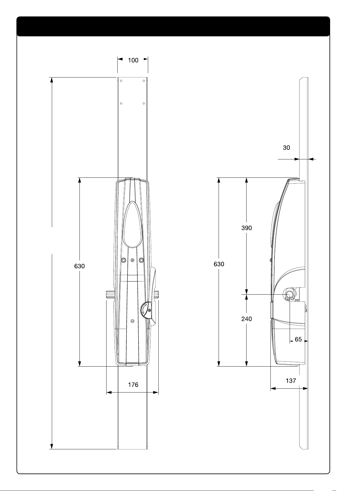
Dimensioni d’ingombro / Overall dimensions / Abmessungen
Dimensions d’encombrement / Dimensiones exteriores / Wymiary gabarytowe
2
Page 3
Braccio del basculante
Arm of the tilting mechanism
Arm des Schwingtors
Bras de la porte basculante
Brazo de la puerta basculante
Ramię bramy uchylnej
1
Curare l’allineamento dei due motori.
Take care to align the two motors.
Die beiden Motoren sorgfältig miteinander fluchten.
Veiller à l’alignement des deux moteurs.
Prestar atención a la alineación de los dos motores.
Ustawianie na osi dwóch siłowników.
Braccio del basculante
Arm of the tilting mechanism
Arm des Schwingtors
Bras de la porte basculante
Brazo de la puerta basculante
Ramię bramy uchylnej
Curare l’allineamento dei due motori.
Take care to align the two motors.
Die beiden Motoren sorgfältig miteinander fluchten.
Veiller à l’alignement des deux moteurs.
Prestar atención a la alineación de los dos motores.
Ustawianie na osi dwóch siłowników.
2 3
3
Page 4
Mettere a livello
Set level
Gerade ausrichten
Mettre de niveau
Nivelar
Wypoziomowanie
Saldare su tutto il contorno
Weld all round the border
Entlang der gesamten Außenlinie schweißen
Souder sur tout le pourtour
Soldar en todo el contorno
Spawać na całym konturze
Mettere a livello
Set level
Gerade ausrichten
Mettre de niveau
Nivelar
Wypoziomowanie
Fissare con n° 4 viti autofilettanti Ø4.8 o con viti M5 o con rivetti Ø4.8.
Secure with 4 self-tapping screws Ø4.8 or with M5 screws or with rivets Ø4.8.
Mit 4 selbstschneidenden Schrauben Ø4.8, mit Schrauben M5 oder Nieten
Ø4.8 befestigen.
Fixer avec n° 4 vis autotaraudeuses Ø 4,8 ou avec vis M5 ou avec rivets Ø 4,8.
Fijar con 4 tornillos de autorrosca Ø4.8 o con tornillos M5 o con remaches Ø4.8.
Mocować za pomocą 4 śrub samogwintujących o Ø 4.8, śrub M5 lub naciętych
gwoździ dwułebkowych o Ø 4.8.
Regolare per ottenere il parallelismo del tubo con la porta basculante
Regulate to obtain parallel positioning of the tube with respect to the overhead door
So regulieren, dass ein perfekter Parallelismus des Rohrs mit dem Schwingtor erhalten wird.
Régler pour obtenir le parallélisme du tube avec la porte basculante
Regular para que el tubo esté paralelo a la puerta basculante
Regulować do momentu równoległego ustawienia rurki z bramą uchyln
Braccio curvo
Curved arm
Gebogener Arm
Bras courbe
Brazo curvo
Ramię zakrzywione
Braccio diritto
Straight arm
Gerader Arm
Bras droit
Brazo recto
Ramię proste
Saldare su tutto il contorno
Weld all round the border
Entlang der gesamten Außenlinie schweißen
Souder sur tout le pourtour
Soldar en todo el contorno
Spawać na całym konturze
Mettere a livello
Set level
Gerade ausrichten
Mettre de niveau
Nivelar
Wypoziomowanie
4 5
6
4
Page 5
Tagliare
Cut
Schneiden
Couper
Cortar
Odciąć
Tubo del braccio diritto
Tube of the straight arm
Rohr des geraden Arms
Tube du bras droit
Tubo del brazo recto
Rurka ramienia prostego
Tagliare
Cut
Schneiden
Couper
Cortar
Odciąć
Piatto del braccio diritto
Flat part of the straight arm
Teller des geraden Arms
P
lat du bras droit
Plato del brazo recto
Listwa prowadnicza ramienia prostego
Saldare su tutto il contorno
Weld all round the border
Entlang der gesamten Außenlinie schweißen
Souder sur tout le pourtour
Soldar en todo el contorno
Spawać na całym konturze
Tagliare
Cut
Schneiden
Couper
Cortar
Odciąć
7
8
5
Page 6
9
10
Per evitare che sporga, il motore può essere montato con la lampada di cortesia verso il basso.
To prevent it protruding, the motor must be fitted with the courtesy light pointing downwards.
Damit der Motor nicht übersteht, kann er so montiert werden, dass die Notbeleuchtung nach unten zeigt.
Pour éviter qu’il dépasse, le moteur peut être monté avec l’éclairage automatique vers le bas.
Para que el motor no sobresalga, se puede montar con la lámpara de cortesía hacia abajo.
By zapobiec wychylaniu się siłownika, można go montować z lampą tylną skierowaną do dołu.
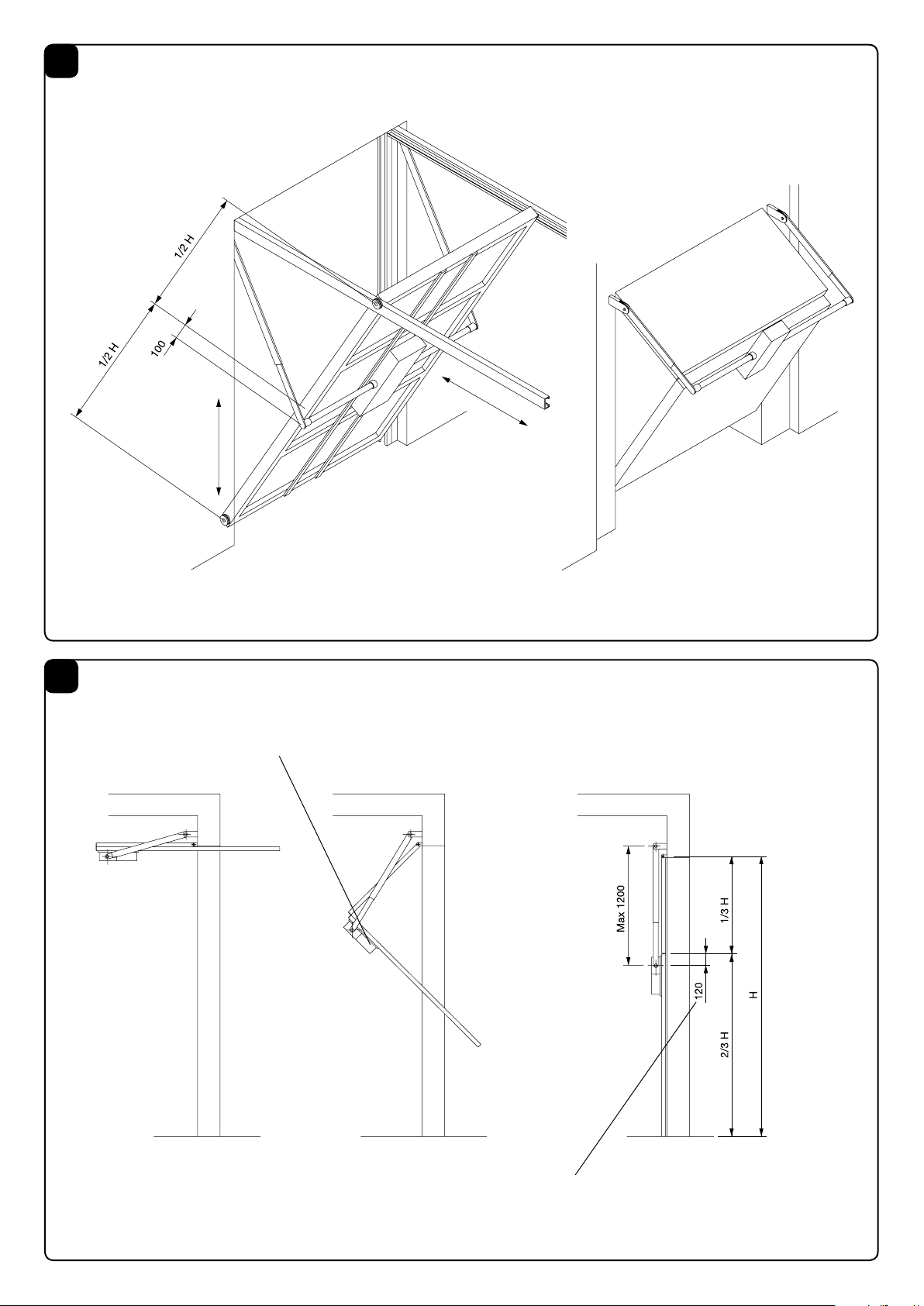
La quota 100 sulle porte basculanti normali diventa 120 dallo snodo del telo basculante all’asse motore.
The height 100 on normal overhead doors becomes 120 from the articulation of the tilting sheet to the motor axis.
Die Quote 100 an normalen Schwingtoren wird zu 120 ab dem Gelenkteil des Schwingtorblatts bis zur Motorachse.
La hauteur 100 sur les portes basculantes normales devient 120 de l’articulation du tablier basculant à l’axe moteur.
La cota 100 en las puertas basculantes normales será de 120 desde la articulación del panel basculante hasta el eje del motor.
Poziom odpowiadający liczbie 100 w przypadku bram uchylnych zwyczajnych dochodzi do 120, odległość od przegubu pancerza uchylnego do wału silnika.
6
Page 7
11
Sblocco per manovra manuale
Release for manual manoeuvring
Entriegelung zur manuellen Bedienung
Déblocage pour manoeuvre manuelle
Desbloqueo para maniobra manual
Rozsprzęglanie dla manewru ręcznego
Funzionamento Automatico
Automatic operation
Automatikbetrieb
Fonctionnement automatique
Funcionamiento automático
Funkcjonowanie automatyczne
Sblocco per manovra manuale
Release for manual manoeuvring
Entriegelung zur manuellen Bedienung
Déblocage pour manoeuvre manuelle
Desbloqueo para maniobra manual
Rozsprzęglanie dla manewru ręcznego
12
Funzionamento Automatico
Automatic operation
Automatikbetrieb
Fonctionnement automatique
Funcionamiento automático
Funkcjonowanie automatyczne
Sblocco per manovra manuale
Release for manual manoeuvring
Entriegelung zur manuellen Bedienung
Déblocage pour manoeuvre manuelle
Desbloqueo para maniobra manual
Rozsprzęglanie dla manewru ręcznego
Registro
Register
Register
Vis de réglage
Tornillo de regulación
Rejestr
Registro
Register
Register
Vis de réglage
Tornillo de regulación
Rejestr
Morsetto
Clamp
Klammer
Serre-câble
Terminal
Zacisk
Rosetta
Washer
Scheibe
Rondelle
Arandela
Podkładka
Vite
Screw
Schraube
Vis
Tornillo
Sruba
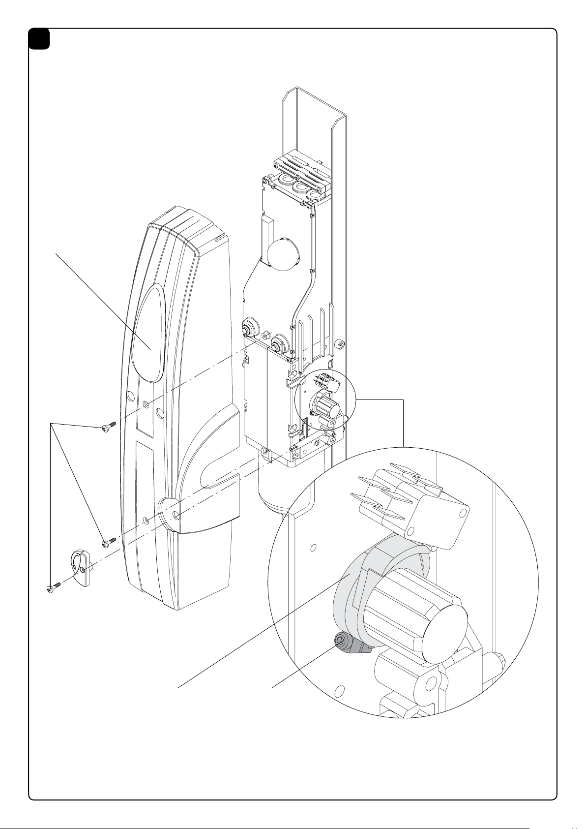
Maniglia con piastra
Handle with plate
Handgriff mit platte
Poignée avec plaque
Manilla con placa
Uchwyt z płytą
Morsetto
Clamp
Klammer
Serre-câble
Terminal
Zacisk
7
Page 8
13
14
15
8
Page 9
16
C
V
AG
9
Page 10

AVVERTENZE
E' vietato l'utilizzo del prodotto per scopi o con modalità non previste nel presente manuale. Usi non corretti possono essere causa
di danni al prodotto e mettere in pericolo persone e cose.
Si declina ogni responsabilità dall'inosservanza della buona
tecnica nella costruzione dei cancelli, nonché dalle deformazioni
che potrebbero verificarsi durante l'uso.
Conservare questo manuale per futuri utilizzi.
L'installazione deve essere effettuata da personale qualificato
nel pieno rispetto delle normative vigenti.
I materiali dell'imballaggio non devono essere lasciati alla portata
dei bambini in quanto fonte di potenziale pericolo. Non disperdere
nell'ambiente i materiali di imballo, ma separare le varie tipologie
(es. cartone, polistirolo) e smaltirle secondo le normative locali.
L’installatore deve fornire tutte le informazioni relative al funzionamento automatico, manuale e di emergenza dell'automazione, e
consegnare all’utilizzatore dell’impianto le istruzioni d’uso.
WARNING
The product shall not be used for purposes or in ways other than
those for which the product is intended for and as described in
this manual. Incorrect uses can damage the product and cause
injuries and damages.
The company shall not be deemed responsible for the noncompliance with a good manufacture technique of gates as well
as for any deformation, which might occur during use.
Keep this manual for further use.
Qualified personnel, in compliance with regulations in force, shall
install the system.
Packaging must be kept out of reach of children, as it can be
hazardous. For disposal, packaging must be divided the various
types of waste (e.g. carton board, polystyrene) in compliance
with regulations in force.
The installer must supply all information on the automatic, manual
and emergency operation of the automatic system and supply
the end user with instructions for use.
Prevedere sulla rete di alimentazione un interruttore/sezionatore onnipolare con distanza
•
Verificare che a monte dell’impianto elettrico vi sia un interruttore differenziale e una protezione di sovracorrente adeguati.
Alcune tipologie di installazione richiedono il collegamento
dell'anta ad un impianto di messa a terra rispondente alle vigenti
norme di sicurezza.
Durante gli interventi di installazione, manutenzione e riparazione,
togliere l’alimentazione prima di accedere alle parti elettriche.
Le descrizioni e le illustrazioni presenti in questo manuale non
sono impegnative. Lasciando inalterate le caratteristiche essenziali del prodotto il fabbricante si riserva il diritto di apportare
qualsiasi modifica di carattere tecnico, costruttivo o commerciale
senza impegnarsi ad aggiornare la presente pubblicazione.
•
Make sure that before wiring an adequate differential switch and
an overcurrent protection is provided.
Pursuant to safety regulations in force, some types of installation
require that the gate connection be earthed.
During installation, maintenance and repair, cut off power supply
before accessing to live parts.
Descriptions and figures in this manual are not binding. While
leaving the essential characteristics of the product unchanged,
the manufacturer reserves the right to modify the same under the
technical, design or commercial point of view without necessarily
update this manual.
d’apertura dei contatti uguale o superiore a 3 mm.
An omnipolar switch/section switch with remote contact opening equal to, or higher than 3mm
must be provided on the power supply mains..
HINWEISE
Das Produkt darf nicht für andere Zwecke oder auf andere Weise
verwendet werden, als in der vorliegenden Anleitung beschrieben.
Ein ungeeigneter Gebrauch kann das Produkt beschädigen und
eine Gefahr für Personen und Sachen darstellen.
Wir übernehmen keinerlei Haftung für Schäden, die sich aus einer
unsachgerechten Montage der Tore und aus daraus folgenden
Verformungen ergeben können.
Bewahren Sie dieses Handbuch für Nachschlagzwecke auf.
Die Installation darf nur von qualifizierten Fachleuten laut den
geltenden Vorschriften vorgenommen werden.
Das Verpackungsmaterial fern von Kindern halten, da es eine
potentielle Gefahr darstellt. Das Verpackungsmaterial nicht ins
Freie werfen, sondern je nach Sorte (z.B. Pappe, Polystyrol) und
laut den örtlich geltenden Vorschriften entsorgen.
Der Installateur hat dem Benutzer alle Informationen über den
automatischen, manuellen Betrieb sowie den Not-Betrieb der
Automatik zusammen mit der Bedienungsanleitung zu liefern.
10
Das Stromnetz muss mit einem allpoligen Schalter bzw.
Trennschalter ausgestattet sein, dessen Kontakte einen
•
Kontrollieren, ob der elektrischen Anlage ein geeigneter Differentialschalter und ein Überspannungsschutzschalter vorgeschaltet sind.
Einige Installationstypologien verlangen den Anschluss des
Flügels an eine Erdungsanlage laut den geltenden Sicherheitsnormen.
Während der Installation, der Wartung und der Reparatur, die
Anlage stromlos machen bevor an den elektrischen Teilen gearbeitet wird.
Die in diesem Handbuch enthaltenen Beschreibungen und Abbildungen sind nicht verbindlich. Ausgenommen der Haupteigenschaften des Produkts, behält sich der Hersteller das Recht vor
eventuelle technische, konstruktive oder kommerzielle Änderungen vorzunehmen ohne dass er vorliegende Veröffentlichung auf
den letzten Stand bringen muss.
Öffnungsabstand gleich oder größer als 3 aufweisen..
Page 11

REGLES DE SECURITE’
Il est interdit d’utiliser ce produit pour l’utilisation du produit ou
avec des finalités ou modalités non prévues par le présent manuel.
Toute autre utilisation pourrait compromettre l’intégrité du produit
et présenter un danger pour les personnes ou pour les biens.
Le fabricant décline toute responsabilité en cas d’utilisation
impropre ou d’inobservation de la bonne technique dans la construction des portails, ainsi que de toute déformation qui pourrait
avoir lieu lors de son utilisation.
Toujours conserver la notice pour toute autre consultation future.
L’installation doit être faite uniquement par un personnel qualifié
dans le respect total des normes en vigueur.
Tenir à l’écart des enfants tous les matériaux d’emballage car ils
représentent une source potentielle de danger. Ne pas disperser
les matériaux d’emballage dans l’environnement, mais trier selon
les différentes typologies (i.e. carton, polystyrène) et les traiter
selon les normes locales.
L’installateur doit fournir toutes les informations relatives au
ADVERTENCIAS
Está prohibido utilizar el producto para finalidades o con modalidades no previstas en el presente manual. Usos incorrectos
pueden causar daños al producto y poner en peligro personas
y cosas.
Se rehúsa cualquier responsabilidad en caso de incumplimiento de la buena técnica en la construcción de las cancelas, así
como en cuanto a las deformaciones que pudieran producirse
durante el uso.
Guardar este manual para futuras consultas. La instalación debe
ser efectuada por personal cualificado respetando plenamente
las normas vigentes.
Los elementos del embalaje no se deben dejar al alcance de los
niños ya que son potenciales fuentes de peligro. No tirar al medio
ambiente los elementos del embalaje, sino que se deben separar
según los varios tipos (por ej. cartón, poliestireno) y evacuarlos
de conformidad con las normas locales.
El instalador debe proporcionar todas las informaciones relativas
al funcionamiento automático, manual y de emergencia de la
automatización y entregar al usuario del equipo las instrucciones
de uso.
fonctionnement automatique, au déverrouillage d’urgence de
l’automatisme, et livrer à l’utilisateur les modes d’emploi.
Prévoir sur le réseau de l’alimentation un interrupteur / sectionneur omnipolaire avec distance d’ou-
•
Vérifier la présence en amont de l’installation électrique d’un
interrupteur différentiel et d’une protection de surcourant
adéquats.
Certains types d’installation requièrent le branchement du vantail à une installation de mise à terre satisfaisant les normes de
sécurité e vigueur.
Avant toute intervention, d’installation, réparation et maintien,
couper l’alimentation avant d’accéder aux parties électriques.
Les descriptions et les illustrations présentées dans ce manuel
ne sont pas contraignantes. En laissant inaltérées les caractéristiques essentielles du produit, le fabricant se réserve le droit d’apporter toute modification à caractère technique, de construction
ou commerciale sans s’engager à revoir la cette publication.
•
Comprobar que entre el aparato y la red eléctrica general haya un interruptor diferencial y una
protección contra sobrecorriente adecuados.
Algunos tipos de instalación requieren que se conecte la hoja
con una instalación de puesta a tierra conforme a las vigentes
normas de seguridad.
Durante las operaciones de instalación, mantenimiento y reparación, cortar la alimentación antes de acceder a las partes
eléctricas.
Las descripciones y las ilustraciones presentadas en este manual
no son vinculantes. Sin cambiar las características esenciales del
producto, el fabricante se reserva el derecho de aportar cualquier
modificación de carácter técnico, constructivo o comercial sin
obligación de actualizar la presente publicación.
verture des contacts égale ou supérieure à 3 mm..
Prever en la red de alimentación un interruptor/
cortacircuitos omnipolar con distancia de apertura de los contactos igual o mayor que 3 mm.
OSTRZEŻENIA
Zabrania się używania produktu do celów i w sposób inny niż
przewidziane w niniejszym podręczniku. Nieprawidłowe używanie
może spowodować uszkodzenie produktu i stanowić zagrożenie
dla osób i rzeczy.
Nie bierze się na siebie żadnej odpowiedzialności za nieprzestrzeganie reguł dobrej techniki budowlanej przy realizacji bram,
a także w przypadku odkształceń, które mogłyby powstać w
trakcie użytkowania.
Przechowywać niniejszy podręcznik do przyszłego użytku.
Instalacja musi być wykonana przez wykwalifikowany personel z
zachowaniem wszelkich obowiązujących przepisów prawnych.
Nie można pozostawiać opakowania w miejscach dostępnych
dla dieci, ponieważ może to być niebezpieczne. Nie pozostawiać
opakowania w środowisku, tylko podzielić na poszczególne kategorie odpadów (n.p. karton, polistyrol) i zlikwidować je zgodnie
z obowiązującymi przepisami miejscowymi.
Instalator zobowiązany jest do udzielenia wszelkich informacji
dotyczących działania w trybie automatycznym, ręcznym i w
przypadku zaistnienia stanu alarmowego automatyzacji i wręczyć
użytkownikowi instalacji instrukcję użytkowania.
Należy przewidzieć w sieci wyłącznik/odłącznik sekcyjny wielobiegunowy, gdzie odległość rozwarcia
między stykami będzie równa lub większa 3 mm..
•
Sprawdzić, czy przed instalacją elektryczną jest odpowiedni
wyłącznik dyferencjalny i zabezpieczenie przed przetężeniem.
Niektóre typologie instalacji wymagają podłączenia skrzydła do uziemienia zgodnego z obowiązującymi normami bezpieczeństwa.
Podczas prac instalacyjnych, konserwacji i naprawy, przed
przystąpieniem do prac na częściach elektrycznych należy odciąć
zasilanie.
Opisy i ilustracje znajdujące się w niniejszym podręczniku podane są wyłącznie przykładowo. Pozostawiając niezmienione
istotne charakterystyki techniczne produktu, producent zastrzega sobie prawo do wprowadzania każdej zmiany o charakterze
technicznym, konstrukcyjnym lub handlowym, bez konieczności
modyfikowania niniejszej publikacji.
11
Page 12

Dichiarazione CE di Conformità
Dichiarazione in accordo alle Direttive 2004/108/CE(EMC); 2006/95/CE(LVD); 2006/42/CE(MD) allegato II, parte B
Fabbricante:Automatismi Benincà SpA
Indirizzo:Via Capitello, 45 - 36066 Sandrigo (VI) - Italia
Dichiara che il prodotto:
Attuatore elettromeccanico 230Vac per porte basculanti modello:
ZED - ZED.E
è conforme alle condizioni delle seguenti Direttive CE:
• DIRETTIVA 2004/108/CE DEL PARLAMENTO EUROPEO E DEL CONSIGLIO del 15 dicembre 2004 concernente il ravvicinamento
delle legislazioni degli Stati membri relative alla compatibilità elettromagnetica e che abroga la direttiva 89/336/CEE, secondo le seguenti norme
armonizzate:
EN 61000-6-2:2005, EN 61000-6-3:2007.
• DIRETTIVA 2006/95/CE DEL PARLAMENTO EUROPEO E DEL CONSIGLIO del 12 dicembre 2006 concernente il ravvicinamento
delle legislazioni degli Stati membri relative al materiale elettrico destinato ad essere adoperato entro taluni limiti di tensione, secondo le seguenti
norme armonizzate:
EN 60335-1:2002 + A1:2004 + A11:2004 + A12:2006 + A2:2006 + A13:2008; EN 60335-1-103:2003.
• DIRETTIVA 2006/42/CE DEL PARLAMENTO EUROPEO E DEL CONSIGLIO del 17 maggio 2006 relativa alle macchine e che modica
la direttiva 95/16/CE, rispettando i requisiti per le “quasi macchine”, secondo la seguente norma armonizzata: EN13241-1:2003.
• Automatismi Benincà SpA dichiara, inoltre, che la documentazione tecnica pertinente è stata compilata in conformità all’allegato VII B della
direttiva 2006/42/CE e che sono stati rispettati i seguenti requisiti essenziali: 1.1.1 - 1.1.2 - 1.1.3 - 1.1.5 - 1.2.1 - 1.2.3 - 1.2.6 - 1.3.1 - 1.3.2 -
1.3.3 - 1.3.4 - 1.3.7 - 1.3.9 - 1.5.1 - 1.5.2 - 1.5.4 - 1.5.5 - 1.5.6 - 1.5.7 - 1.5.8 - 1.5.10 - 1.5.11 - 1.5.13 - 1.6.1 - 1.6.2 - 1.6.4 - 1.7.2 - 1.7.4 - 1.7.4.1
- 1.7.4.2 - 1.7.4.3.
• Il produttore si impegna a trasmettere alle autorità nazionali, in risposta ad una motivata richiesta, le informazioni pertinenti sulla “quasi macchina”. L’impegno comprende le modalità di trasmissione e lascia impregiudicati i diritti di proprietà intellettuale del fabbricante della “quasi
macchina”.
• Si comunica che la “quasi macchina” non deve essere messa in servizio nché la macchina nale in cui deve essere incorporata non è stata
dichiarata conforme, se del caso, alle disposizioni della direttiva 2006/42/CE.
Benincà Luigi, Responsabile legale.
Sandrigo, 02/11/2010.
INTRODUZIONE
Ci congratuliamo con Voi per aver scelto il motoriduttore ZED. Tutti gli articoli della vasta gamma Benincà sono il frutto di una ventennale esperienza nel settore degli automatismi e di una continua
ricerca di nuovi materiali e di tecnologie all’avanguardia. Proprio
per questo, oggi siamo in grado di offrire dei prodotti estremamente affidabili che, grazie alla loro potenza, efficacia e durata,
soddisfano pienamente le esigenze dell’utente finale. Tutti i nostri
prodotti vengono costruiti in conformità alle normative vigenti e
sono coperti da garanzia. Inoltre, una polizza R. C. prodotti stipulata con primaria compagnia assicurativa copre eventuali danni a
cose o persone causati da difetti di fabbricazione.
1. NOTIZIE GENERALI
Per un buon funzionamento dell’automazione in oggetto, la porta
basculante deve rispondere alle seguenti caratteristiche:
- buona robustezza e rigidità
- buona equilibratura
- buona scorrevolezza delle guide.
In ogni caso l’apertura e la chiusura manuali devono potersi eseguire con facilità.
2. CARATTERISTICHE GENERALI
ZED è un’automazione per porte basculanti a contrappesi, a montaggio centrale o laterale. Compatto e lineare, il motoriduttore ZED
si adatta a qualsiasi tipo di porta basculante. ZED oltre a garantire
il massimo dell’affidabilità, offre un movimento continuo, regolare
e silenzioso. L’applicazione è di facile esecuzione e può avvenire
mediante viti o saldatura. L’irreversibilità del motoriduttore assicura la chiusura della porta senza l’impiego di elettroserrature. In
caso di mancanza di corrente lo sblocco avviene mediante la semplice rotazione di una manopola situata sul motoriduttore.
3. ACCESSORI PER IL MONTAGGIO
Montaggio centrale con saldature:
• piastra per fissaggio AU.65 (650 mm), AU.125 (1250 mm) o
AU.20 (2000 mm);
• coppia di tubi zincati con bussola AU.45Z (1500 mm) oppure
AU.45ZL (2000 mm);
• coppia di bracci dritti zincati AU2.D; se manca spazio utilizzare
la coppia di bracci curvi zincati AU2.C (vedi fig. 6).
Montaggio centrale senza saldature:
• piastra per fissaggio AU.65 (650 mm), AU.125 (1250 mm) o
AU.20 (2000 mm);
• coppia di tubi zincati con bussola AU.45Z (1500 mm) oppure
AU.45ZL (2000 mm);
• coppia di bracci dritti con bussola AU2.DNS (600 mm).
Montaggio laterale con saldature:
• piastra per fissaggio AU.65 (650 mm), AU.125 (1250 mm) o
AU.20 (2000 mm);
• bussola calettata AU.45B; se il motoriduttore è troppo lontano
dal bordo della porta utilizzare la coppia di tubi con bussola saldata AU2.45T (150 mm);
• coppia di bracci dritti zincati AU2.D; se manca spazio utilizzare
la coppia di bracci curvi zincati AU2.C (vedi fig. 6).
Montaggio laterale senza saldature:
• piastra per fissaggio AU.65 (650 mm), AU.125 (1250 mm) o
AU.20 (2000 mm);
• coppia di bracci dritti con bussola saldata AU2.D45 (600 mm)
oppure AU2.D45L (2000 mm); se il motoriduttore è troppo lontano
dal bordo della porta utilizzare la coppia di tubi con bussola saldata AU2.45T (150 mm) con la coppia di bracci dritti con bussola
AU2.DNS (600 mm).
12
Page 13

4. ACCESSORI SUPPLEMENTARI
- Sblocco da esterno con chiave personalizzata ZED.E.
- Sblocco dainterno/esterno a maniglia con chiave personalizzata
ZED.SE.
- ZED.MS sblocco a filo.
5. MESSA IN POSA DELL’AUTOMATISMO
L’automazione con un solo motore a montaggio centrale è consigliabile per porte basculanti di area inferiore od uguale a 12 m
per dimensioni superiori o per basculanti con portina utilizzare n°
2 motori laterali.
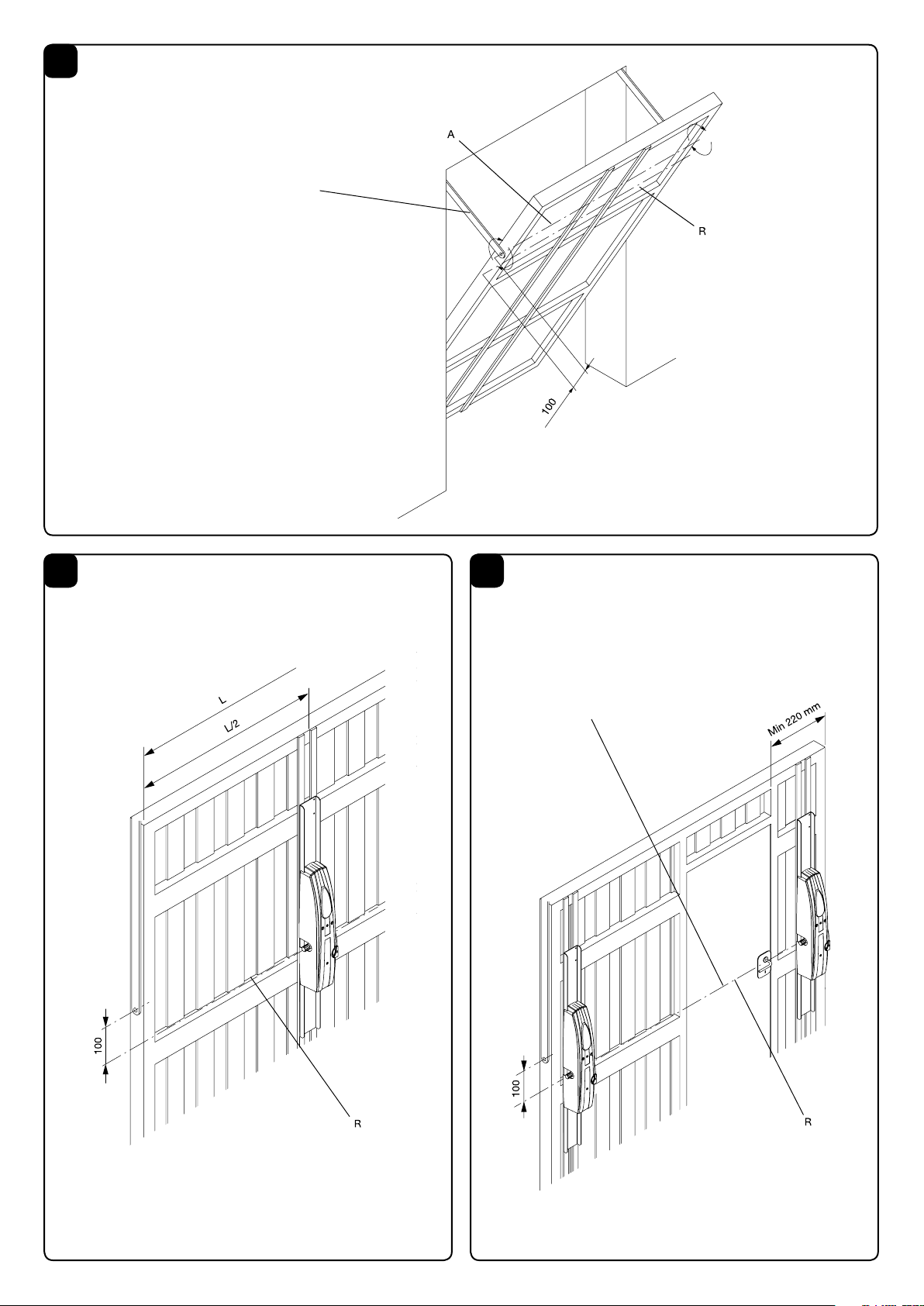
1) Individuato l’asse di rotazione della porta basculante A, determinare l’asse R passante inferiormente alla distanza di 100 mm (fig.
1); questo è l’asse dell’albero scanalato uscente dal motoriduttore.
Ancorare quindi la piastra del motoriduttore alla porta seguendo le
indicazioni delle figg. 2 e 3.
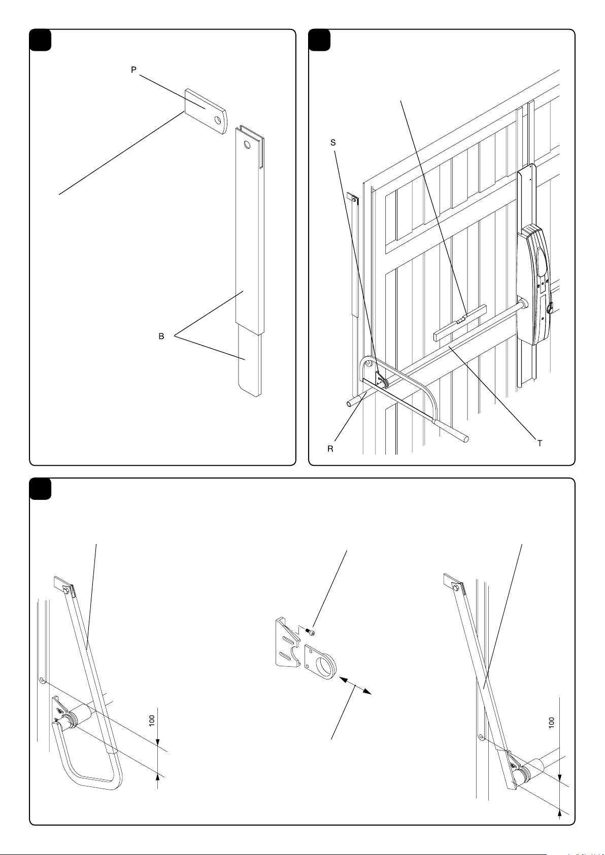
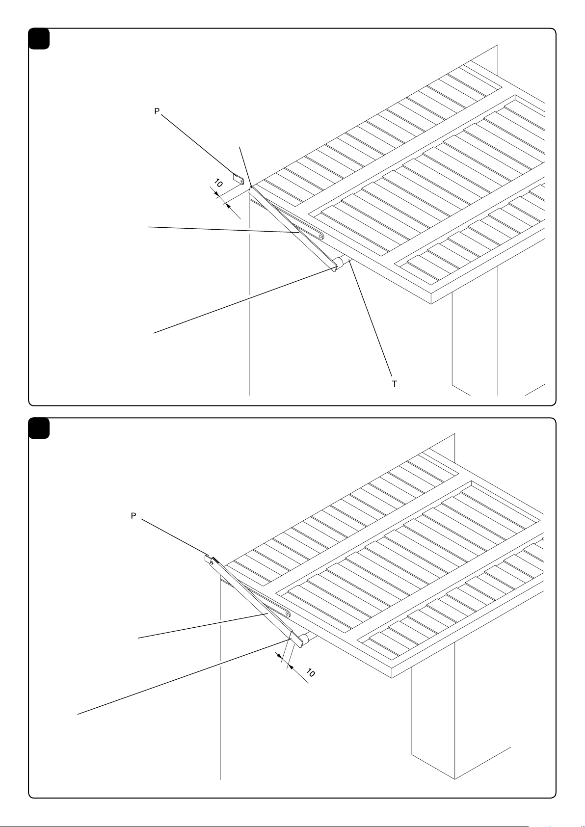
2) Fissare la piastrina P sul montante o sul traverso superiore della basculante oppure a muro a fianco del braccio della porta. (In
ogni caso il braccio B deve essere sistemato tra il montante ed il
braccio della porta basculante; se questo spazio è insufficiente
utilizzare il braccio curvo art. AU2.C che permette di lavorare in
asse con il braccio della porta basculante).
3) Fissare provvisoriamente la staffa S con il tubo T infilato sia in
quest’ultima che nell’albero scanalato del motoriduttore.
Rilevare la misura del tubo T in modo che sia allineato al braccio B.
Tagliare quindi il tubo a misura. Fissare ora la staffa S mediante viti
o rivetti avendo cura di mettere in bolla il tubo T (fig. 5). Quest’ultimo deve anche essere parallelo al telo della basculante; a tal
proposito usufruire della regolazione di cui fig. 6.
4) Portare la porta basculante in apertura e tagliare i due componenti del braccio dritto secondo le indicazioni delle figg. 7 e 8.
Saldare poi il piatto del braccio al tubo T (fig. 7) oppure utilizzare il braccio AU2.D45. Infilare il piatto nel tubo e quindi fissare
quest’ultimo al piatto P mediante vite M10 e dado autobloccante
(in dotazione).
5) Se necessario riequilibrare la porta aumentando i contrappesi
o il tiro delle molle in modo che le manovre manuali risultino facili
da compiere.
2
6. APPLICAZIONI PARTICOLARI
Oltre alle normali porte basculanti (a contrappeso e guide verticali), ZED consente di automatizzare:
• Porte a guide orizzontali e verticali fig. 9 (l’installazione risulta
analoga a quella descritta al punto 5).
• Porte basculanti snodate. Per l’installazione seguire il punto 5
integrato con le indicazioni di fig.10.
• Porte basculanti a molla (per il montaggio seguire le indicazioni
del punto 5).
N.B.: Per poter essere automatizzate queste porte devono però
essere a guida verticale.
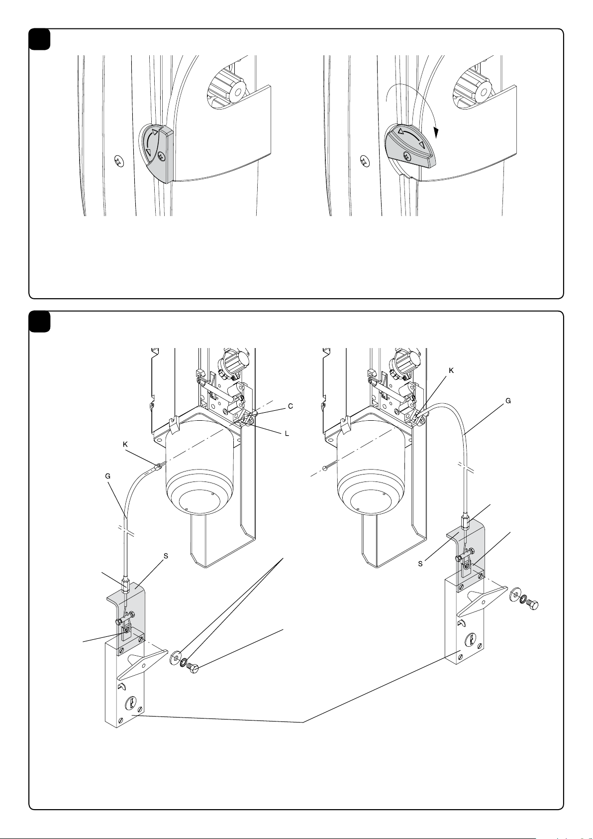
7. MANOVRA MANUALE
La manovra manuale della porta basculante è realizzabile in diversi
modi:
Sblocco interno a maniglia:
• Ruotare di 90° la manopola di sblocco come indicato in Fig.11
• L'automazione è così disinserita. E' ora possibile aprire/chiudere
manualmente l'anta.
• Per ripristinare il funzionamento automatico, riportare la manopola di sblocco nella posizione iniziale.
Sblocco a filo art. ZED.MS:
Nota: Lo sblocco a filo può essere installato con la guaina a sinistra o a destra dell'attuatore, a seconda della posizione della
maniglia di apertura della porta. In fig.12 sono illustrate entrambe
le installazioni.
E' necessario praticare un piccolo foro per il passagio della guai-
na, le quote di foratura, valide per entrambi i lati del carter sono
indicate in fig.13.
• Infilare il cavo di acciaio C sulla leva L.
• Passare la guaina G con il capocorda K fino a mandarla in battuta sul corpo carter del motore (Nel caso di guaina a destra il cavo
viene inserito dalla parte opposta e il capocorda K va in battuta
sulla leva L).
• Fissare il cavo di acciaio C nella maniglia con il morsetto come
indicato in fig. 12.
;
• Fissare la staffa S.
• Mettere in tensione il cavo utilizzando la vite di registro.
• Ruotare la maniglia per sbloccare.
• Ruotando nuovamente la maniglia, la prima manovra ripristinerà
il normale funzionamento.
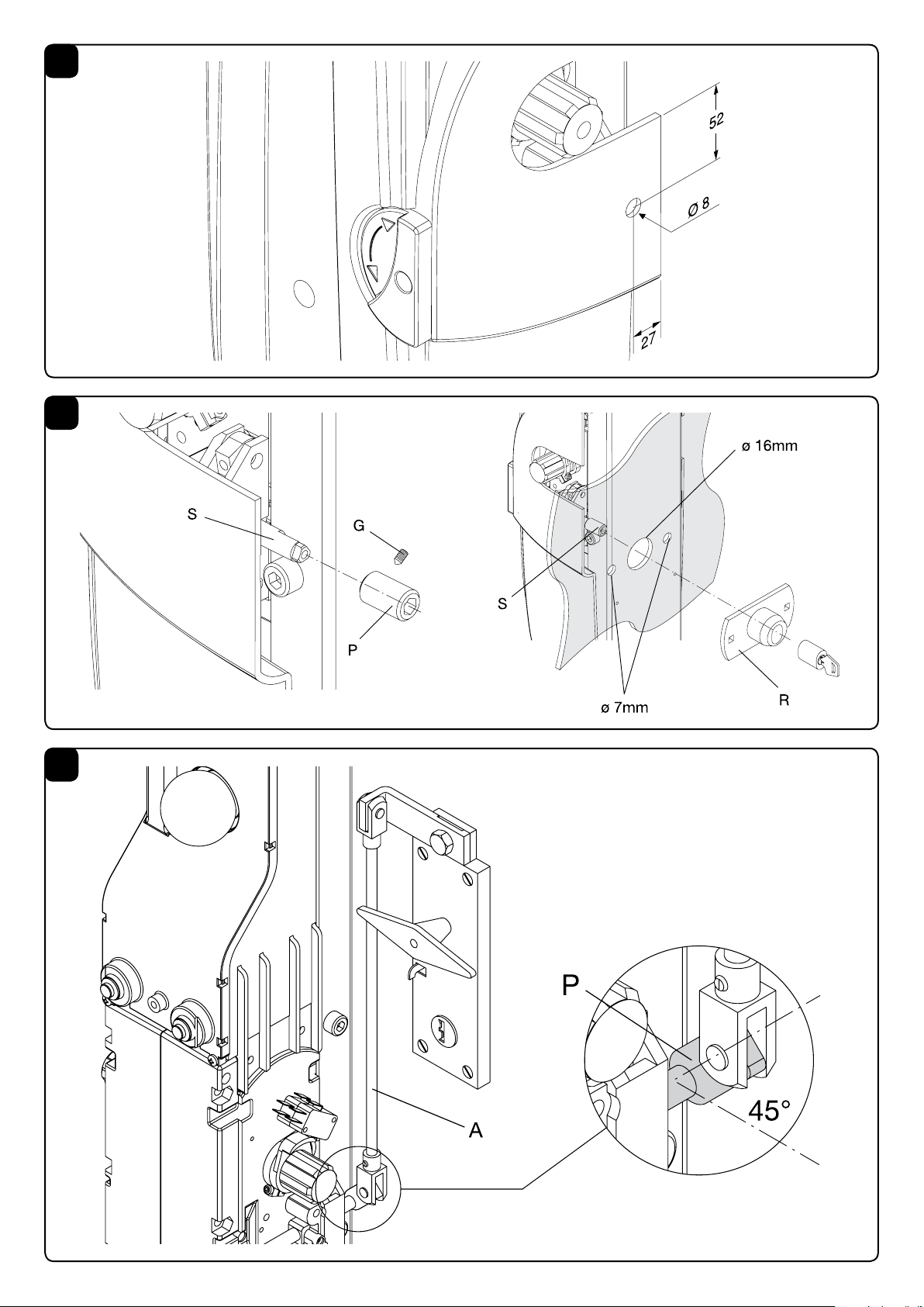
Sblocco esterno con chiave personalizzata ZED.E:
• Fissare il perno P, al perno di sblocco S utilizzando l’apposito
grano G, come indicato in figura 14.
• In asse con il perno di sblocco S realizzare un foro di circa 16mm
di diametro.
• Utilizzando la piastrina R come dima di foratura realizzare i due
fori laterali ø 7 mm per le viti di fissaggio.
• Fissare la piastrina alla porta.
Sblocco interno/esterno a maniglia con chiave personalizzata
ZED.SE:
• Fissare la piastrina P prima di montare l'attuatore, in posizione
45° come indicato in Fig.15.
• Provedere al montaggio dello sblocco tagliando l'astina A a misura.
8. REGOLAZIONE DEI FINECORSA
ZED dispone di finecorsa incorporati sia per l’apertura che per la
chiusura, per la regolazione agire come segue (fig. 16):
• Svitare la vite V e togliere il carter C.
• Allentare il grano G.
• Ritardare o anticipare l’intervento del finecorsa ruotando la camma A e serrare moderatamente il grano G.
ATTENZIONE
La polizza RC prodotti, che risponde di eventuali danni a cose o
persone causati da difetti di fabbricazione, richiede la conformità
dell’impianto alle normative vigenti e l’utilizzo di accessori originali
Benincà.
DATI TECNICI ZED
Alimentazione
Assorbimento.
Potenza nominale
Coppia nominale
Intermittenza lavoro
Tempo apertura
Grado di protezione
Interv. termoprotez.
Temp. funzionamento
Condensatore
Rumorosità
Lubrificazione
Peso
*Disponibile versione IP44
230Vac (50Hz)
1,5A
340W
350Nm
30%
≈14s
IP40*
130°C
-20°C/+50°C
10μF
<70dB
AGIP GRLP1
10 kg
13
Page 14

CE Declaration of Conformity
Declaration in accordance with Directives 2004/108/CE(EMC); 2006/95/CE(LVD);2006/42/CE(MD) Annex II, part B
The Manufacturer:Automatismi Benincà SpA
Address:Via Capitello, 45 - 36066 Sandrigo (VI) - Italy
Declares that the product:
Electromechanical actuator 230 V AC for tilt-up doors, model:
ZED - ZED.E
conforms with the requirements of the following EC Directives:
• DIRECTIVE 2004/108/CE OF THE EUROPEAN PARLIAMENT AND COUNCIL, 15 December 2004, in relation to the harmonisation of
the legislation of member states regarding electromagnetic compatibility , in abrogation of Directive 89/336/CEE, per the following harmonised
standards:
EN 61000-6-2:2005, EN 61000-6-3:2007.
• DIRECTIVE 2006/95/CE OF THE EUROPEAN PARLIAMENT AND COUNCIL, 12 December 2006, in relation to the harmonisation of the
legislation of member states regarding electrical material intended to be used within certain voltage ranges, per the following harmonised standards:
EN 60335-1:2002 + A1:2004 + A11:2004 + A12:2006 + A2:2006 + A13:2008; EN 60335-1-103:2003.
• DIRECTIVE 2006/42/CE OF EH EUROPEAN PARLIAMENT AND COUNCIL, 17 May 2006, in relation to machinery, amending Directive
95/16/CE, in relation to the requisites for “partly completed machinerys”, per the following harmonised standard: EN13241-1:2003.
• Automatismi Benincà SpA declares, furthermore, that the pertinent technical documentation has been completed in conformity with Annex VII
B of Directive 2006/42/CE and that the following essential requisites have been satised: 1.1.1 - 1.1.2 - 1.1.3 - 1.1.5 - 1.2.1 - 1.2.3 - 1.2.6 - 1.3.1
- 1.3.2 - 1.3.3 - 1.3.4 - 1.3.7 - 1.3.9 - 1.5.1 - 1.5.2 - 1.5.4 - 1.5.5 - 1.5.6 - 1.5.7 - 1.5.8 - 1.5.10 - 1.5.11 - 1.5.13 - 1.6.1 - 1.6.2 - 1.6.4 - 1.7.2 - 1.7.4
- 1.7.4.1 - 1.7.4.2 - 1.7.4.3.
• The manufacturer agrees to forward the pertinent information regarding the "partly completed machinery" to the national authorities if justiably
requested to do so. This agreement includes the means of transmission and does not affect the manufacturer's intellectual property rights.
• The "partly completed machinery" may not be put into service unless the machine into which it is to be incorporated has been declared conforming - as applicable - to the requirements of Directive 2006/42/CE.
Benincà Luigi, Legal representative.
Sandrigo, 02/11/2010.
INTRODUCTION
We congratulate you for choosing the ZED gear motor. All the
items in the vast Benincà range are the fruit of twenty years of experience in the sector of automatisms and of a continuous search
for new materials and state-of-the-art technologies. For this very
reason, today we are able to offer extremely reliable products
which, thanks to their power, efficiency and long life, fully satisfy
the demands of the end user. All our products are made in conformity with the regulations in force and are covered by guarantee.
Moreover, a TPL policy stipulated with a leading insurance company covers any damage to persons or things caused by manufacturing defects.
1. GENERAL INFORMATION
For good operation of this automation, the overhead door must
possess the following characteristics:
- good robustness and rigidity
- good balancing
- good sliding of the guides.
In any case, it must be possible to perform manual opening and
closing with ease.
2. GENERAL CHARACTERISTICS
ZED is an automation for overhead doors with counterweights, for
central or side assembly. Compact and linear, the ZED gear motor adapts to any type of overhead door. As well as guaranteeing
maximum reliability, ZED offers a continuous, regular and silent
movement. It is easy to fit using screws or welding. The gear motor
is irreversible which ensures that the door can be closed without
the use of electric locks. In the event of a power cut the door may
be released by simply turning a knob on the gear motor.
3. ACCESSORIES FOR ASSEMBLY
Central assembly with welding:
• fitting plate AU.65 (650 mm), AU.125 (1250 mm) or AU.20 (2000
mm);
• pair of galvanized tubes with bush AU.45Z (1500 mm) or AU.45ZL
(2000 mm);
• pair of galvanized straight arms AU2.D. If there is no space, use
the pair of galvanized bent arms AU2.C (see Fig. 6).
Central assembly with welding:
• fitting plate AU.65 (650 mm), AU.125 (1250 mm) or AU.20 (2000
mm);
• pair of galvanized tubes with bush AU.45Z (1500 mm) or AU.45ZL
(2000 mm);
• pair of straight arms with bush AU2.DNS (600 mm).
Central assembly with welding:
• fitting plate AU.65 (650 mm), AU.125 (1250 mm) or AU.20 (2000
mm);
• splined bush AU.45B; if the geared motor is too far from the edge
of the door, use the pair of tubes with welded bush AU2.45T (150
mm);
• pair of galvanized straight arms AU2.D. If there is no space, use
the pair of galvanized bent arms AU2.C (see Fig. 6).
Lateral assembly without welding:
• fitting plate AU.65 (650 mm), AU.125 (1250 mm) or AU.20 (2000 mm);
• pair of straight arms with welded bush AU2.D45 (600 mm) or
AU2.D45L (2000 mm); if the geared motor is too far from the edge
of the door, use the pair of tubes with welded bush AU2.45T (150
mm) with the pair of straight arms with bush AU2.DNS (600 mm).
14
Page 15

4. ADDITIONAL ACCESSORIES
- External release with customized key ZED.E.
- Release from inside/outside by means of a handle with customized key ZED.SE.
- ZED.MS wire release.
5. INSTALLING THE AUTOMATISM
The automation with only one motor and central assembly is recommended for overhead doors with an area less than or equal to
12 m2; for larger dimensions or for overhead doors with a built-in
small door use 2 side motors.
1) After identifying the axis of rotation of the overhead door A,
determine the axis R passing through the bottom at a distance of
100 mm (fig. 1); this is the axis of the splined shaft that comes out
of the gear motor.
Then anchor the plate of the gear motor to the door following the
indications in figs. 2 and 3.
2) Fix the plate P onto the upright or the upper cross member of
the overhead door or onto the wall next to the arm of the door. (In
any case the arm B must be positioned between the upright and
the arm of the overhead door; if this space is insufficient, use the
curved arm art. AU.C which allows you to work in axis with the arm
of the overhead door (fig. 4).
3) Provisionally fix the bracket S with the tube T, inserted both into
the bracket and into the splined shaft of the gear motor.
Measure the tube T so that it is aligned with the arm B.
Then cut the tube to size.
Now fix the bracket S with screws or rivets, taking care to set the
tube T absolutely level (fig. 5).
The tube must also be parallel to the sheet of the overhead door;
to ensure this, regulate as shown in fig. 6.
4) Bring the overhead door into open position and cut the two
components of the straight arm following the indications in figs.
7 and 8.
Then weld the flat part of the arm to the tube T (fig. 7) or use the
arm AU2.D45.
Insert the flat part in the tube and then fix the latter to the flat part
P with a screw M10 and self-locking nut (provided).
5) If necessary rebalance the door by increasing the counterweights or the pull of the springs so that manual manoeuvres can
be performed easily.
dle for opening the door. Fig. 12 shows both installations.
It is necessary to make a small hole for the sheath to pass through;
the drilling measurements, valid for both sides of the casing, are
indicated in fig.13.
• Fit the steel cable C onto the lever L.
• Pass the sheath G with the cable terminal K until it rests against
the motor casing body (If the sheath is on the right the cable is
inserted from the opposite side and the cable terminal K rests
against the lever L).
• Fix the steel cable C in the handle with the terminal as indicated
in fig. 12.
• Fix the bracket S.
• Tighten the cable using the registering screw.
• Turn the handle to release it.
• When the handle is turned again, the first manoeuvre will restore
normal operation.
External release with customised key ZED.E:
• Fix the pin P to the release pin S using the special dowel G, as
indicated in figure 14.
• On axis with the release pin S, make a hole with a diameter of
about 16mm.
• Using the plate R as a drilling template, make the two holes at
the sides ø 7 mm for the fixing screws.
• Fix the plate to the door.
Release from inside/outside by means of a handle with customized key ZED.SE:
• Fix the plate P before fitting the actuator, in position 45° as indicated in Fig.15.
• Assemble the release mechanism, cutting the rod A to size.
8. REGULATION OF THE LIMIT STOPS
ZED has built-in limit stops both for opening and for closing; to
regulate them, proceed as follows (fig. 16):
• Unscrew the screw V and remove the casing C.
• Slacken the dowel G.
• Delay or anticipate the intervention of the limit stop by rotating
the cam A and moderately tighten the dowel G.
ATTENTION
The TPL policy on the products, which covers any damage to persons or things caused by manufacturing defects, requires that the
system comply with the regulations in force and that authentic Benincà accessories be used.
6. PARTICULAR APPLICATIONS
As well as ordinary overhead doors (with counterweight and vertical guides), ZED can be used for the automated operation of:
• Doors with horizontal and vertical guides, fig. 9 (the installation is
similar to that described in point 5).
• Articulated overhead doors. For installation follow point 5 integrated with the indications in fig.10.
• Overhead doors with a spring (for installation follow the indications in point 5).
N.B.: In order to be automated these doors must have a vertical
guide.
7. MANUAL MANOEUVRE
The manual manoeuvre of the overhead door may be achieved in
various ways:
Internal release of the handle:
• Turn the release knob by 90° as indicated in Fig.11
• In this way the automation is deactivated. It is now possible to
open/close the door by hand.
• To restore automatic operation, return the release knob to its
initial position.
Wire release art. ZED.MS:
Note: The wire release may be installed with the sheath on the left
or the right of the actuator, depending on the position of the han-
TECHNICAL DATA ZED
Power supply
Consumption
Power
Torque
Jogging
Operating time
IP class
Thermal switch trig.
Operat. temperature
Capacitor
Noise level
Lubrication
Weight
*Available version IP44
230Vac (50Hz)
-20°C/+50°C
AGIP GRLP1
1,5A
340W
350Nm
30%
≈14s
IP40*
130°C
10μF
<70dB
10 kg
15
Page 16

CE-Konformitätserklärung
Erklärung im Einklang mit den Richtlinien 2004/108/CE(EMC); 2006/95/CE(LVD); 2006/42/CE(MD) Anhang II, Teil B
Hersteller:Automatismi Benincà SpA
Anschrift:Via Capitello, 45 - 36066 Sandrigo (VI) - Italien
Erklärt, dass das Produkt:
Elektromechanischer 230Vac-Antrieb für Schwingtore, Modell:
ZED - ZED.E
die Bedingungen der folgenden CE-Richtlinien erfüllt:
• RICHTLINIE 2004/108/CE DES EUROPÄISCHEN PARLAMENTS UND EUROPARATS vom15. Dezember 2004 in Bezug auf die
Annäherung der Rechtsprechungen der Mitgliedsstaaten über die elektromagnetische Kompatibilität, welche die Richtlinie 89/336/CEE laut den
folgenden harmonisierten Normen:
EN 61000-6-2:2005, EN 61000-6-3:2007.
• RICHTLINIE 2006/95/CE DES EUROPÄISCHEN PARLAMENTS UND EUROPARATS vom 12. Dezember 2006 in Bezug auf die
Annäherung der Rechtsprechungen der Mitgliedsstaaten über elektrische Betriebsmittel zur Verwendung innerhalb bestimmter Spannungsgrenzen
laut den folgenden harmonisierten Normen:
EN 60335-1:2002 + A1:2004 + A11:2004 + A12:2006 + A2:2006 + A13:2008; EN 60335-1-103:2003.
• RICHTLINIE 2006/42/CE DES EUROPÄISCHEN PARLAMENTS UND EUROPARATS vom 17. Mai 2006 in Bezug auf Maschinen,
welche die Richtlinie 95/16/CE ändert, unter Einhaltung der Requisiten für „unvollständige Maschinen“, entsprechend der folgenden harmonisierten Norm: EN13241-1:2003.
• Automatismi Benincà SpA erklärt darüber hinaus, dass die zugehörige technische Dokumentation in Konformität mit dem Anhang VII B der
Richtlinie 2006/42/CE ausgefüllt wurde und dass die folgenden essentiellen Voraussetzungen erfüllt wurden: 1.1.1 - 1.1.2 - 1.1.3 - 1.1.5 - 1.2.1 -
1.2.3 - 1.2.6 - 1.3.1 - 1.3.2 - 1.3.3 - 1.3.4 - 1.3.7 - 1.3.9 - 1.5.1 - 1.5.2 - 1.5.4 - 1.5.5 - 1.5.6 - 1.5.7 - 1.5.8 - 1.5.10 - 1.5.11 - 1.5.13 - 1.6.1 - 1.6.2
- 1.6.4 - 1.7.2 - 1.7.4 - 1.7.4.1 - 1.7.4.2 - 1.7.4.3.
• Der Hersteller verpichtet sich, den nationalen Behörden als Antwort auf eine begründete Anfrage die die unvollständige Maschine“ betreffenden
Informationen zu übermitteln. Die Verpichtung umfasst die Übermittlungsmodalität und lässt die Rechte am geistigen Eigentum des Herstellers
der „unvollständigen Maschine“ unberührt.
• Es wird darauf hingewiesen, dass die „unvollständige Maschine“ nicht in Betrieb genommen werden darf, solange die endgültige Maschine, in
die sie eingebaut werden soll, nicht als konform mit der Richtlinie 2006/42/CE erklärt wurde.
Benincà Luigi, Leiter der Rechtsabteilung.
Sandrigo, den 02.11.2010.
EINFÜHRUNG
Wir beglückwünschen Sie zum Kauf des Getriebemotors ZED.
Alle Artikel des reichen Benincà-Angebots sind das Ergebnis einer
zwanzigjährigen Erfahrung auf dem Gebiet der Automatisierung
und der ständigen Erforschung neuer Materialien und moderner
Technologien. Eben darum sind wir heute in der Lage, extrem zuverlässige Produkte anzubieten, die dank ihrer Leistungsfähigkeit,
Effizienz und Haltbarkeit alle Anforderungen des Endverbrauchers
voll erfüllen. Alle unsere Produkte werden in Konformität mit den
einschlägigen Normen konstruiert und sind mit einer Garantie ausgestattet. Daneben gewährleistet eine Produkthaftpflichtversicherung bei einer führenden Versicherungsagentur die Deckung eventueller Sach- oder Personenschäden, die durch Fabrikationsfehler
entstehen können.
1. ALLGEMEINE HINWEISE
Für die einwandfreie Funktion der Automatisierung muss das
Schwingtor folgende Merkmale aufweisen:
- gute Robustheit und Steifigkeit
- gute Auswuchtung
- gutes Gleitvermögen der Führungen.
Die manuelle Bedienung für Öffnen und Schließen muss in jedem
Fall problemlos sein.
2. ALLGEMEINE MERKMALE
ZED ist eine Automatisierung für Schwingtore mit Gegengewicht
mit seitlicher oder zentraler Montage. Der kompakte, lineare Getriebemotor ZED eignet sich für jeden Schwingtortyp. ZED garantiert
nicht nur für maximale Zuverlässigkeit, sondern bietet eine kontinuierliche, flüssige und geräuschlose Bewegung. ZED ist einfach
anzubringen und kann angeschraubt oder angeschweißt werden.
Die Nichtumkehrbarkeit des Getriebemotors sorgt für den zuverlässigen Verschluss des Tors, ohne Einsatz von Elektroschlössern.
Im Falle eines Stromausfalls erfolgt die Entriegelung einfach durch
Verstellen des Drehknopfs am Getriebemotor.
3. MONTAGE ZUBEHÖR
Zentrale Montage gelötet:
• Befestigungsplatte AU.65 (650 mm), AU.125 (1250 mm) oder
AU.20 (2000 mm);
• zwei verzinkte Rohrleitungen mit Buchse AU.45Z (1500 mm)
oder AU.45ZL (2000 mm);
• zwei gerade Arme (verzinkt) AU2.D; bei Platzmangel die beiden
gebogenen Arme (verzinkt) AU2.C verwenden (siehe Abb. 6).
Zentrale Montage nicht gelötet:
• Befestigungsplatte AU.65 (650 mm), AU.125 (1250 mm) oder
AU.20 (2000 mm);
• zwei verzinkte Rohrleitungen mit Buchse AU.45Z (1500 mm)
oder AU.45ZL (2000 mm);
• zwei gerade Arme mit Buchse AU2.DNS (600 mm).
Seitliche Montage gelötet:
• Befestigungsplatte AU.65 (650 mm), AU.125 (1250 mm) oder
AU.20 (2000 mm);
• verbundene Buchse AU.45B; falls der Getriebemotor zu weit von
dem Türrand entfernt ist, die beiden Rohrleitungen mit gelöteter
Buchse AU2.45T (150 mm) verwenden;
• zwei gerade Arme (verzinkt) AU2.D; bei Platzmangel die beiden
gebogenen Arme (verzinkt) AU2.C verwenden (siehe Abb. 6).
Seitliche Montage nicht gelötet:
• Befestigungsplatte AU.65 (650 mm), AU.125 (1250 mm) oder
AU.20 (2000 mm);
• zwei gerade Arme mit gelöteter Buchse AU2.D45 (600 mm) oder
AU2.D45L (2000 mm); falls der Getriebemotor zu weit von dem
Türrand entfernt ist, die beiden Rohrleitungen mit gelöteter Buchse AU2.45T (150 mm) zusammen mit den beiden geraden Armen
mit Buchse AU2.DNS (600 mm) verwenden.
16
Page 17

4. OPTIONALES ZUBEHÖR
- Entriegelung von außen mittels personalisiertes Schlüssels ZED.E.
- Griff-Entriegelung von innen/außen mit personalisiertem Schlüssel ZED.SE.
- ZED.MS Kabel-Entriegelung
5. INSTALLATION DER TORAUTOMATISIERUNG
Die Torautomatisierung mit nur einem, mittig montierten Motor
empfiehlt sich für Schwingtore mit einer Fläche bis 12 m2; währendfür größere Tore oder für Schwingtore mit Durchgangstür vorzugsweise zwei seitliche Motoren zu verwenden sind.
1) Die Drehachse des Schwingtors A ausmachen und die Achse R
bestimmen, die mit einem Abstand von 100 mm (Abb. 1) unter
A verläuft; dies ist die Keilwelle, die aus dem Getriebemotor austritt.
Nun die Platte des Getriebemotors gemäß der Anweisungen der
Abb. 2 und 3 am Tor verankern.
2) Das Plättchen P am Ständer oder am oberen Querträger des
Schwingtors, oder aber an der Wand, seitlich des Torarms befestigen. (Der Arm B muss in jedem Fall zwischen Ständer und
Arm des Schwingtors angebracht werden; wenn nicht genügend
Platz zur Verfügung steht, einfach den gebogenen Arm Art. AU.C
verwenden, der das axial zum Arm des Schwingtors ausgerichtete
Arbeiten ermöglicht) (Abb. 4).
3) Den Bügel S provisorisch befestigen, wobei das Rohr T sowohl
an diesem, als auch an der Keilwelle des Getriebemotors eingesteckt sein muss.
Das Maß des Rohrs T aufnehmen, so dass es mit dem Arm B gefluchtet wird.
Jetzt das Rohr zuschneiden.
Nun den Bügel S mit Schrauben oder Nieten befestigen, wobei
das Rohr T gerade auszurichten ist (Abb. 5).
Das Rohr muss auch parallel zum Schwingtorblatt stehen; zu diesem Zweck die Einstellung der Abb. 6 nutzen.
4) Das Schwingtor öffnen und die beiden Teile des geraden Arms
gemäß der Anweisungen der Abb. 7 und 8 zuschneiden.
Dann den Teller des Arms am Rohr T anschweißen (Abb. 7), oder
den Arm AU2.D45 verwenden.
Den Teller in das Rohr einführen und letzteres mittels Schraube
M10 und selbstsperrender Mutter (mitgeliefert) am Teller P befestigen.
5) Falls erforderlich das Tor erneut auswuchten, indem die Gegengewichte vermehrt oder der Zug der Federn verstärkt wird, so
dass die manuelle Bedienung einfach auszuführen ist.
6. SONDERANWENDUNGEN
Neben normalen Schwingtoren (mit Gegengewichten und vertikalen Führungen) ermöglicht ZED die Automatisierung der folgenden
Tore:
• Tore mit horizontalen und vertikalen Führungen Abb. 9 (die Installation ist wie die unter Punkt 5 beschriebene).
• Gelenk-Schwingtore. Für die Installation den Punkt 5 und die
Anweisungen der Abb.10 befolgen.
• Schwingtore mit Feder (für die Installation die Anweisungen des
Punkts 5 befolgen).
NB: Derlei Tore müssen jedoch vertikale Führungen haben, damit
sie automatisiert werden können.
7. MANUELLE BEDIENUNG
Die manuelle Bedienung der Schwingtore ist auf verschiedene Arten möglich:
Entriegelung von Innen mit Griff:
• Den Entriegelungsknauf um 90° drehen, wie in der Abb.11 gezeigt.
• Damit ist die Automatisierung ausgeschlossen und das Tor kann
von Hand geöffnet und geschlossen werden.
• Um den Automatikbetrieb wieder herzustellen, den Entriegelungsknauf auf die Ausgangsposition zurückstellen.
Kabel-Entriegelung Art. ZED.MS:
Hinweis: Die Kabel-Entriegelung kann mit Hülle links oder rechts
vom Trieb installiert werden, je nach Position des Torgriffs. In der
Abb.12 sind beide Installationsmöglichkeiten aufgezeigt.
Dazu muss ein kleines Bohrloch für den Durchgang der Hülle ausgeführt werden. Die Bohrquoten, die für beide Seiten des Gehäuses gelten, sind in der Abb.13 angegeben.
• Das Stahlkabel C am Hebel L einführen.
• Die Hülle G mit dem Kabelschuh K bis zum Anschlag am Körper
des Motorgehäuses durchführen (Bei Hülle an der rechten Seite
wird das Kabel an der entgegengesetzten Seite eingeführt und der
Anschlag des Kabelschuhs K ist der Hebel L).
• Den Bügel S befestigen.
• Das Stahlkabel C mit der Klemme am Griff befestigen, wie in der
Abb. 12 gezeigt.
• Das Kabel mit Hilfe der Stellschraube spannen.
• Den Griff drehen, um zu entriegeln.
• Den Griff erneut drehen, das erste Manöver stellt den normalen
Betrieb wieder her.
Äußere Entriegelung mit personalisiertem Schlüssel ZED.E:
• Den Bolzen P mit dem speziellen Stift G am Entriegelungsbolzen
S befestigen, wie in der Abbildung 14 gezeigt.
• Axial zum Entriegelungsbolzen S ein Bohrloch mit zirka 16 mm
Durchmesser erstellen.
• Unter Verwendung des Plättchens R als Bohrschablone die beiden seitlichen Löcher mit ø 7 mm für die Befestigungsschrauben
erstellen.
• Das Plättchen am Tor befestigen.
Innere/äußere Griff-Entriegelung mit personalisiertem Schlüssel ZED.SE:
• Das Plättchen P befestigen, bevor der Trieb in einer 45°-Position
installiert wird, wie in der Abb.15 gezeigt.
• Nun die Entriegelung montieren, indem der Stab A maßgenau
zugeschnitten wird.
8. EINSTELLEN DER ENDSCHALTER
ZED ist mit eingebauten Endschaltern für Öffnen und Schließen
ausgestattet, die wie folgt eingestellt werden (Abb. 16):
• Die Schraube V aufschrauben und das Gehäuse C ausbauen.
• Den Stift G lockern.
• Das Auslösen des Endschalters vor- oder nachverlegen, indem
der Nocken A verstellt wird, und den Stift G mäßig
festziehen.
ACHTUNG
Die Produkthaftpflichtpolice, die eventuelle Sach- oder Personenschäden deckt, die durch Fabrikationsfehler entstehen können,
setzt die Konformität der Anlage mit den einschlägigen Vorschriften und die Verwendung von Originalzubehör von
Benincà voraus.
TECHNISCHE DATEN ZED
Speisung
Stromaufnahme
Leistung
Drehmoment
Betriebsschaltung
Betätigungszeit
IP Grad
Temperaturschutzschalter
Betriebstemperatur
Kondensator
Geräuschentwicklung
Schmierung
Gewicht
*Vorhandene Version IP44
230Vac (50Hz)
1,5A
340W
350Nm
30%
≈14s
IP40*
130°C
-20°C/+50°C
10μF
<70dB
AGIP GRLP1
10 kg
17
Page 18

Déclaration de conformité CE
Déclaration en accord avec les Directives 2004/108/CE(CEM); 2006/95/CE(DBT); 2006/42/CE(DM) annexe II, partie B
Fabricant :Automatismi Benincà SpA
Adresse :Via Capitello, 45 - 36066 Sandrigo (VI) - ITALIE
Déclare que le produit :
Actionneur électromécanique 230 Vca pour portes basculantes modèle :
ZED - ZED.E
est conforme aux conditions des Directives CE suivantes :
• DIRECTIVE 2004/108/CE DU PARLEMENT EUROPÉEN ET DU CONSEIL du 15 décembre 2004 concernant le rapprochement des législa-
tions des États membres relatives à la compatibilité électromagnétique et qui abroge la directive 89/336/CEE, selon les normes harmonisées suivantes :
EN 61000-6-2:2005, EN 61000-6-3:2007.
• DIRECTIVE 2006/95/CE DU PARLEMENT EUROPÉEN ET DU CONSEIL du mardi 12 décembre 2006 concernant le rapprochement des
législations des États membres relatives au matériel électrique destiné à être employé dans certaines limites de tension, selon les normes harmonisées suivantes :
EN 60335-1:2002 + A1:2004 + A11:2004 + A12:2006 + A2:2006 + A13:2008; EN 60335-1-103:2003.
• DIRECTIVE 2006/42/CE DU PARLEMENT EUROPÉEN ET DU CONSEIL du 17 mai 2006 relative aux machines et qui modie la directive
95/16/CE, en respectant les exigences pour les « quasimachines», selon la norme harmonisée suivante :
EN13241-1:2003.
• Automatismi Benincà SpA déclare en outre que la documentation technique pertinente a été remplie en conformité avec l'annexe VII B de la
directive 2006/42/CE et que les exigences essentielles suivantes ont été respectées : 1.1.1 - 1.1.2 - 1.1.3 - 1.1.5 - 1.2.1 - 1.2.3 - 1.2.6 - 1.3.1 - 1.3.2
- 1.3.3 - 1.3.4 - 1.3.7 - 1.3.9 - 1.5.1 - 1.5.2 - 1.5.4 - 1.5.5 - 1.5.6 - 1.5.7 - 1.5.8 - 1.5.10 - 1.5.11 - 1.5.13 - 1.6.1 - 1.6.2 - 1.6.4 - 1.7.2 - 1.7.4 - 1.7.4.1
- 1.7.4.2 - 1.7.4.3.
• Le fabricant s'engage à transmettre aux autorités nationales, en réponse à une demande motivée, les informations pertinentes relatives à la «
quasi-machine ». L'engagement comprend les modalités de transmission et ne porte pas atteinte aux droits de propriété intellectuelle du fabricant
de la « quasi-machine ».
• Il est communiqué que la « quasi-machine » ne doit pas être mise en service tant que la machine nale sur laquelle elle doit être incorporée n'a
pas été déclarée conforme, le cas échéant, aux dispositions de la directive 2006/42/CE.
Benincà Luigi, Responsable légal.
Sandrigo, 02/11/2010.
INTRODUCTION
Nous vous félicitons d’avoir choisi l’opérateur ZED. Tous les articles
de la vaste gamme Benincà sont le fruit de vingt ans d’expérience
dans le secteur des automatismes et d’une recherche continue de
nouveaux matériaux et de technologies à l’avant-garde. C’est justement pourquoi nous sommes aujourd’hui en mesure d’offrir des
produits extrêmement fiables qui, grâce à leur puissance, à leur
efficacité et à leur durée, satisfont pleinement les exigences de
l’utilisateur final. Tous nos produits sont construits en conformité
avec les normes en vigueur et sont couverts par une garantie. De
plus, une assurance R.C. produits stipulée avec une compagnie
de premier plan couvre les éventuels dommages aux choses ou
aux personnes causés par des défauts de fabrication.
1. GÉNÉRALITÉS
Pour un bon fonctionnement de l’automatisme en question, la
porte basculante doit satisfaire les caractéristiques
suivantes :
- bonne robustesse et rigidité
- bon équilibrage
- bon coulissement des rails de guidage.
Dans tous les cas, l’ouverture et la fermeture manuelles doivent
pouvoir s’effectuer facilement.
2. CARACTÉRISTIQUES GÉNÉRALES
ZED est un automatisme pour portes basculantes à contrepoids,
à montage central ou latéral. Compact et linéaire, l’opérateur ZED
s’adapte à n’importe quel type de porte basculante. ZED, en plus
de garantir le maximum de la fiabilité, offre un mouvement continu,
régulier et silencieux. L’application est facile à exécuter et peut se
faire au moyen de vis ou par soudage. L’irréversibilité de l’opérateur assure la fermeture de la porte sans nécessité de serrure électrique. En cas d’interruption du courant, le déblocage s’effectue
par simple rotation d’une poignée située sur l’opérateur.
3.
ACCESSOIRES POUR LE MONTAGE
Montage central avec soudures:
• plaque de fixation AU.65 (650 mm), AU.125 (1250 mm) ou AU.20
(2000 mm);
• couple de tubes galvanisés avec douille AU.45Z (1500 mm) ou
bien AU.45ZL (2000 mm);
• couple de bras droits galvanisés AU2.D; s’il n’y a pas assez de
place utiliser le couple de bras courbes galvanisés AU2.C (voir
fig. 6).
Montage central sans soudures:
• plaque de fixation AU.65 (650 mm), AU.125 (1250 mm) ou AU.20
(2000 mm);
• couple de tubes galvanisés avec douille AU.45Z (1500 mm) ou
bien AU.45ZL (2000 mm);
• couple de bras droits galvanisés avec douille AU2.DNS (600
mm).
Montage latéral avec soudures:
• plaque de fixation AU.65 (650 mm), AU.125 (1250 mm) ou AU.20
(2000 mm);
• douille sertie AU.45B; si le motoréducteur est trop loin du bord
de la porte utiliser le couple de tubes avec douille soudée AU2.45T
(150 mm);
• couple de bras droits galvanisés AU2.D; s’il n’y a pas assez de
place utiliser le couple de bras courbes galvanisés AU2.C (voir
fig. 6).
Montage latéral sans soudures:
• plaque de fixation AU.65 (650 mm), AU.125 (1250 mm) ou AU.20
(2000 mm);
• couple de bras droits avec douille soudée AU2.D45 (600 mm)
ou bien AU2.D45L (2000 mm); si le motoréducteur est trop loin du
bord de la porte utiliser le couple de tubes avec douille soudée
AU2.45T (150 mm) avec le couple de bras droits avec douille AU2.
DNS (600 mm).
18
Page 19

4. ACCESSOIRES SUPPLÉMENTAIRES
- Déblocage de l’extérieur avec clé personnalisée ZED.E.
- Déblocage de l’intérieur/extérieur à poignée avec clé personnalisée ZED.SE.
- ZED.MS déblocage par câble.
5. MISE EN PLACE DE L’AUTOMATISME
L’automatisation avec un seul moteur à montage central est adapté à des portes basculantes d’une surface inférieure ou égale à 12
m²; en cas de dimensions supérieures ou de tablier basculant avec
porte piéton incorporée utiliser n° 2 moteurs latéraux.
1) Après avoir identifié l’axe de rotation de la porte basculante A,
déterminer l’axe R passant en dessous à la distance de
100 mm (fig. 1); c’est l’axe de l’arbre cannelé sortant de l’opérateur.
Fixer ensuite la plaque de l’opérateur à la porte en suivant les indications des fig. 2 et 3.
2) Fixer la platine P sur le montant ou sur la traverse supérieure
de la porte basculante ou bien au mur à côté du bras de la porte.
(Dans tous les cas, le bras B doit être placé entre le montant et le
bras de la porte basculante ; si cet espace est insuffisant, utiliser
le bras courbe art. AU2.C qui permet un fonctionnement dans le
même axe que le bras de la porte basculante) (fig. 4).
3) Fixer provisoirement la patte S avec le tube T enfilé dans cette
dernière et dans l’arbre cannelé de l’opérateur.
Prendre la mesure du tube T de manière qu’il soit aligné avec le
bras B.
Couper ensuite le tube à la dimension mesurée.
Fixer la patte S avec des vis ou des rivets en veillant à mettre de
niveau le tube T (fig. 5).
Ce dernier doit être parallèle également au tablier de la porte basculante ; utiliser pour cela le réglage décrit dans la fig. 6.
4) Ouvrir la porte basculante et couper les deux composants du
bras droit suivant les indications des fig. 7 et 8.
Souder ensuite le plat du bras au tube T (fig. 7) ou bien utiliser le
bras AU2.D45.
Enfiler le plat dans le tube puis fixer celui-ci au plat P avec une vis
M10 et un écrou indesserrable (inclus dans la fourniture).
5) Si nécessaire, rééquilibrer la porte en augmentant les contrepoids ou la traction exercée par les ressorts de manière que les
manoeuvres manuelles soient plus faciles à accomplir.
6. APPLICATIONS PARTICULIÈRES
En plus des portes basculantes normales (avec contrepoids et
rails verticaux), ZED permet d’automatiser :
• Portes à rails horizontaux ou verticaux fig. 9 (l’installation est
analogue à celle qui est décrite au point 5).
• Portes basculantes articulées (fig. 10). Pour l’installation, suivre
le point 5 complété par les indications de la
fig.10.
• Portes basculantes à ressort (pour le montage suivre les indications du point 5).
N.B.: Pour pouvoir être automatisées, ces portes doivent être avec
rail vertical.
7. MANOEUVRE MANUELLE
La manoeuvre manuelle de la porte basculante est réalisable de
différentes manières :
Déblocage interne à poignée:
• Tourner de 90° la poignée de déblocage comme l’indique la
Fig.11
• L’automatisme est ainsi désactivé. Il est maintenant possible
d’ouvrir et de fermer manuellement la porte.
• Pour rétablir le fonctionnement automatique, remettre la poignée
de déblocage dans la position initiale.
Déblocage par câble art. ZED.MS:
Note: le déblocage par câble peut être installé avec la gaine à
gauche ou à droite de l’opérateur, suivant la position de la poignée
d’ouverture de la porte. La fig.12 illustre les deux types d’installations.
Il faut faire un petit trou pour le passage de la gaine, les positions
du perçage, valables pour les deux côtés du carter sont indiqués
dans la fig.13.
• Enfiler le câble en acier C sur le levier L.
• Passer la gaine G avec l’extrémité K de manière à ce qu’elle
aille toucher le corps du carter du moteur (Dans le cas de gaine à
droite, le câble est inséré de l’autre côté et l’extrémité K va toucher
le levier L).
• Fixer le câble en acier C dans la poignée avec le serre-câble
comme l’indique la fig. 12.
• Fixer la patte S.
• Tendre le câble en utilisant la vis de réglage.
• Tourner la poignée pour débloquer.
• En tournant de nouveau la poignée, la première manoeuvre rétablira le fonctionnement normal.
Déblocage extérieur avec clé personnalisée ZED.E:
• Fixer le pivot P au pivot de déblocage S en utilisant le goujon G,
comme l’indique la figure 14.
• Dans l’axe avec le pivot de déblocage S faire un trou d’environ
16 mm de diamètre.
• Utilisant la platine R comme gabarit de perçage, faire deux trous
latéraux ø 7 mm pour les vis de fixation.
• Fixer la platine à la porte.
Déblocage intérieur/extérieur à poignée avec clé personnalisée ZED.SE:
• Fixer la platine P avant de monter l’opérateur, à 45° comme l’indique la Fig.15.
• Monter le dispositif de déblocage en coupant la tige A à la bonne
dimension.
8. RÉGLAGE DES FINS DE COURSE
ZED dispose de fins de course incorporés tant pour l’ouverture
que pour la fermeture; pour leur réglage, procéder de la façon suivante (fig. 16):
• Dévisser la vis V et enlever le carter C.
• Desserrer le goujon G.
• Retarder ou anticiper l’intervention du fin de course en tournant
la came A et serrer modérément le goujon G.
ATTENTION
L’assurance R.C. produits, qui répond des éventuels dommages
aux choses ou aux personnes causés par des défauts de fabrication est subordonnée à la conformité de l’installation aux normes
en vigueur et l’utilisation d’accessoires
originaux Benincà.
DONNEES TECHNIQUE ZED
Alimentation
Absorption
Puissance
Couple
Intermittence travail
Temps manoeuvre
Degré IP
Interv. protect. therm.
Temp. fonctionnement
Condensateur
Bruit
Lubrification
Poids
*Disponible version IP44
230Vac (50Hz)
1,5A
340W
350Nm
30%
≈14s
IP40*
130°C
-20°C/+50°C
10μF
<70dB
AGIP GRLP1
10 kg
19
Page 20

Declaración CE de Conformidad
Declaración según las Directivas 2004/108/CE(EMC); 2006/95/CE(LVD); 2006/42/CE(MD) anexo II, parte B
Fabricante:Automatismi Benincà SpA
Dirección:Via Capitello, 45 - 36066 Sandrigo (VI) - Italia
Declara que el producto:
Mando electromecánico 230Vac para puertas basculantes modelo:
ZED - ZED.E
es conforme a las condiciones de las siguientes Directivas CE:
• DIRECTIVA 2004/108/CE DEL PARLAMENTO EUROPEO Y DEL CONSEJO del 15 de diciembre de 2004 sobre la armonización de las
legislaciones de los Estados miembros sobre la compatibilidad electromagnética y que abroga la directiva 89/336/CEE, según las siguientes normas
armonizadas:
EN 61000-6-2:2005, EN 61000-6-3:2007.
• DIRECTIVA 2006/95/CE DEL PARLAMENTO EUROPEO Y DEL CONSEJO del 12 de diciembre de 2006 sobre la armonización de las
legislaciones de los Estados miembros sobre el material eléctrico destinado a implementarse dentro de determinados límites de tensión, según las
siguientes normas armonizadas:
EN 60335-1:2002 + A1:2004 + A11:2004 + A12:2006 + A2:2006 + A13:2008; EN 60335-1-103:2003.
• DIRECTIVA 2006/42/CE DEL PARLAMENTO EUROPEO Y DEL CONSEJO del 17 de mayo de 2006 sobre las máquinas y que modica
la directiva 95/16/CE, respetando los requisitos para las “cuasimáquinas”, según la siguiente norma armonizada: EN13241-1:2003.
• Automatismi Benincà SpA declara asimismo que la documentación técnica pertinente ha sido compilada de conformidad con el anexo VII B de
la directiva 2006/42/CE y que se han respetado los siguientes requisitos esenciales: 1.1.1 - 1.1.2 - 1.1.3 - 1.1.5 - 1.2.1 - 1.2.3 - 1.2.6 - 1.3.1 - 1.3.2
- 1.3.3 - 1.3.4 - 1.3.7 - 1.3.9 - 1.5.1 - 1.5.2 - 1.5.4 - 1.5.5 - 1.5.6 - 1.5.7 - 1.5.8 - 1.5.10 - 1.5.11 - 1.5.13 - 1.6.1 - 1.6.2 - 1.6.4 - 1.7.2 - 1.7.4 - 1.7.4.1
- 1.7.4.2 - 1.7.4.3.
• El fabricante se compromete a transmitir información pertinente a la “cuasi-máquina” a las autoridades nacionales ante cualquier solicitud motivada.
El compromiso comprende las modalidades de transmisión y no perjudica los derechos de propiedad intelectual del fabricante de la “cuasi-máquina”.
• Se comunica que la “cuasi-máquina” no debe ponerse en funcionamiento hasta que la máquina nal en la que deba incorporarse no haya sido
declarada conforme, si es el caso, a las disposiciones de la directiva 2006/42/CE.
Benincà Luigi, Responsable legal.
Sandrigo, 02/11/2010.
INTRODUCCIÓN
Les felicitamos por su elección del motorreductor ZED. Todos
los artículos de la extensa gama Benincà son el resultado de la
experiencia conseguida en veinte años de actividad en el sector
de automatizaciones, conjugada a una constante investigación de
nuevos materiales y tecnologías a la vanguardia. Y gracias a ello,
hoy estamos capacitados para ofertarles productos sumamente
fiables que, gracias a su potencia, eficacia y duración, cumplen
plenamente las exigencias del usuario final. Todos nuestros productos se fabrican en observancia a las normativas vigentes y
están cubiertos con garantía. Asimismo, la póliza RC productos
estipulada con una de las más acreditadas compañía de seguros,
cubre los daños tanto a cosas como a personas debidos a defectos de fabricación.
1. NOTICIAS GENERALES
Para un buen funcionamiento de la automatización en objeto, la
puerta basculante debe tener las siguientes características:
- buena solidez y rigidez
- buen equilibrado
- buen deslizamiento de las guías.
De cualquier modo, la apertura y el cierre manuales se deberán
poder realizar con facilidad.
2. CARACTERÍSTICAS GENERALES
ZED es una automatización para puertas basculantes de contrapesas, de montaje central o lateral. Compacto y lineal, el motorreductor ZED se adapta a todo tipo de puerta basculante. Además
de garantizar máxima fiabilidad, ZED ofrece un movimiento continuo, regular y silencioso. Es fácil de aplicar, tanto con tornillos
como a través de soldadura. La irreversibilidad del motorreductor
asegura el cierre de la puerta sin emplear electrocerraduras. En
caso de fallo de suministro de la corriente eléctrica, la puerta se
desbloquea girando simplemente el pomo puesto en el motorreductor.
3.
ACCESORIOS PARA EL MONTAJE
Montaje central con soldaduras:
• placa para fijación AU.65 (650 mm), AU.125 (1250 mm) ó AU.20
(2000 mm);
• pareja de tubos galvanizado con casquillo AU.45Z (1500 mm) o
bien AU.45ZL (2000 mm);
• pareja de brazos rectos galvanizados AU2.D; si falta espacio,
utilizar la pareja de brazos curvados galvanizados AU2.C (véase
la fig. 6).
Montaje central sin soldaduras:
• placa para fijación AU.65 (650 mm), AU.125 (1250 mm) ó AU.20
(2000 mm);
• pareja de tubos galvanizado con casquillo AU.45Z (1500 mm) o
bien AU.45ZL (2000 mm);
• pareja de brazos rectos con casquillo AU2.DNS (600 mm).
Montaje lateral con soldaduras:
• placa para fijación AU.65 (650 mm), AU.125 (1250 mm) ó AU.20
(2000 mm);
• casquillo ensamblado AU.45B; si el motorreductor está demasiado lejos del borde de la puerta, utilizar la pareja de tubos con
casquillo soldado AU2.45T (150 mm);
• pareja de brazos rectos galvanizados AU2.D; si falta espacio,
utilizar la pareja de brazos curvados galvanizados AU2.C (véase
la fig. 6).
Montaje lateral sin soldaduras:
• placa para fijación AU.65 (650 mm), AU.125 (1250 mm) ó AU.20
(2000 mm);
• pareja de brazos rectos con casquillo soldado AU2.D45 (600
mm) o bien AU2.D45L (2000 mm); si el motorreductor está demasiado lejos del borde de la puerta, utilizar la pareja de tubos
con casquillo soldado AU2.45T (150 mm) con la pareja de brazos
rectos con casquillo AU2.DNS (600 mm).
20
Page 21

4. ACCESORIOS SUPLEMENTARIOS
- Desbloqueo desde el exterior con llave personalizada ZED.Y.
- Desbloqueo desde el interior /exterior de manilla con llave personalizada ZED.SE.
- ZED.MS desbloqueo con cable.
5. COLOCACIÓN DE LA AUTOMATIZACIÓN
La automatización con un sólo motor de montaje central es aconsejada para puertas basculantes de área inferior o igual a 12 m2;
para tamaños mayores o para basculantes con puerta utilizar 2
motores laterales.
1) Identificado el eje de rotación de la puerta basculante A, determinar el eje R que pasa por abajo, a una distancia de
100 mm (fig. 1); este es el eje del árbol ranurado que sale del motorreductor.
Luego anclar la placa del motorreductor en la puerta según las
indicaciones de las figs. 2 y 3.
2) Fijar la placa P en el montante o en el travesaño superior de
la puerta basculante, o bien en la pared al lado del brazo de la
puerta. (De cualquier modo, el brazo B estará colocado entre el
montante y el brazo de la puerta basculante; de ser insuficiente
este espacio, utilizar el brazo curvo art. AU.C que permite trabajar
en eje con el brazo de la puerta basculante) (fig. 4).
3) Fijar el estribo S en el tubo T de forma provisional, y que está
introducido en éste y en el árbol ranurado del motorreductor.
Medir el tubo T, de forma que esté alineado con el brazo B.
Cortar ahora el tubo a medida.
Fijar ahora el estribo S con los tornillos o remaches, teniendo cuidado de nivelar el tubo T (fig.5).
Asimismo, el tubo estará paralelo al panel de la basculante, y para
ello utilizar la regulación indicada en la fig. 6.
4) Poner la puerta basculante en posición de apertura y cortar los
dos componentes del brazo recto siguiendo las indicaciones
de las figs. 7 y 8.
Luego soldar la placa del brazo al tubo T (fig. 7) o utilizar el brazo
AU2.D45.
Introducir la placa en el tubo y fijar éste en la placa P con el tornillo
M10 y la tuerca de seguridad (en equipamiento).
5) De ser necesario, reequilibrar la puerta aumentando los contrapesos o la tensión de los muelles, a fin de que las maniobras
manuales resulten fáciles.
6. APLICACIONES PARTICULARES
Además de las normales puertas basculantes (de contrapeso y
guías verticales), con ZED se automatizan:
• Puertas de guías horizontales y verticales fig. 9 (se instalan de
forma análoga a la descrita en el punto 5).
• Puertas basculantes articuladas. Para la instalación seguir el
punto 5 integrado con las indicaciones de la fig.10.
• Puertas basculantes de muelle (para el montaje seguir las indicaciones del punto 5).
N.B.: Se podrán automatizar estas puertas a condición de que
sean de guía vertical.
7. MANIOBRA MANUAL
La maniobra manual de la puerta basculante se ejecuta de varias
maneras:
Desbloqueo interno de manilla:
• Girar 90° el pomo de desbloqueo como se indica en la fig.11
• Ahora la automatización está deshabilitada y es posible abrir/
cerrar la puerta de forma manual.
• Para restablecer el funcionamiento automático, poner el pomo
de desbloqueo en posición original.
Desbloqueo con cable art. ZED.MS:
Nota: El desbloqueo con cable se puede instalar con la vaina a
la izquierda o a la derecha del actuador, según la posición de la
manilla de apertura de la puerta. En la fig.12 se ilustran las dos
instalaciones.
Es necesario realizar un pequeño orificio para pasar la vaina, las
medidas del orificio, válidas para los dos lados del cárter, aparecen en la fig.13.
• Meter el cable de acero C en la palanca L.
• Pasar la vaina G con el terminal del cable K hasta el fondo del
cárter del motor (en el caso de vaina a la derecha, el cable se mete
por la parte contraria y el terminal del cable K va hasta el fondo
de la palanca L).
• Fijar el cable de acero C en la manilla con el borne como aparece
en la fig. 12.
• Fijar el estribo S.
• Tensar el cable a través del tornillo de regulación.
• Girar la manilla para el desbloqueo.
• Girar la manilla otra vez, la primera maniobra restablecerá el funcionamiento normal.
Desbloqueo exterior con llave personalizada ZED.E:
• Fijar el perno P en el perno de desbloqueo S utilizando el correspondiente tornillo sin cabeza G, como aparece
en la figura 14.
• En eje con el perno de desbloqueo S realizar un orificio de aprox.
16 mm de diámetro.
• Sirviéndose de la placa R como plantilla de taladro, realizar los
dos orificios laterales ø 7 mm para los tornillos
de fijación.
• Fijar la placa en la puerta.
Desbloqueo interior/exterior de manilla con llave personalizada ZED.SE:
• Antes de montar el actuador, fijar la placa P en posición 45°
como se indica en la fig.15.
• Montar el desbloqueo cortando la varilla A a medida.
8. REGULACIÓN DE LOS FINES DE CARRERA
ZED incorpora fines de carrera tanto para la apertura como para el
cierre, y se regulan de este modo (fig. 16):
• Extraer el tornillo V y quitar el cárter C.
• Aflojar el tornillo sin cabeza G.
• Retardar o anticipar la intervención de los fines de carrera girando el álabe A y apretar con moderación el tornillo sin cabeza G.
ATENCIÓN
La póliza RC productos que cubre los daños ocasionados a cosas
o a personas por defectos de fabricación, requiere el cumplimiento de la instalación de las normativas vigentes y el uso de accesorios originales Benincà.
DATOS TÉCNICOS ZED
Alimentación
Consumo
Potencia
Par
Intermitencia operación
Tiempo maniobra
Índice IP
Interv. termoprotección
Temp. funcionamiento
Condensador
Ruido
Lubrificación
Peso
*Disponible versión IP44
230Vac (50Hz)
1,5A
340W
350Nm
30%
≈14s
IP40*
130°C
-20°C/+50°C
10μF
<70dB
AGIP GRLP1
10 kg
21
Page 22

Deklaracja zgodności CE
sporządzona zgodnie z dyrektywami europejskimi 2004/108/WE (EMC) i 2006/95/WE (LVD)
Producent: Automatismi Benincà SpA
Adres: Via Capitello, 45 - 36066 Sandrigo (VI) - Włochy
oświadcza, że produkt:
Automatyzm do bram sekcyjnych model:
ZED - ZED.E
jest zgodny z wymogami następujących uchylnych WE:
• DYREKTYWY 2004/108/WE RADY I PARLAMENTU EUROPEJSKIEGO z dnia 15 grudnia 2004r. w sprawie zbliżania ustawodawstwa państw
członkowskich w zakresie kompatybilności elektromagnetycznej i anulującej postanowienia dyrektywy 89/336/EWG, zgodnie z następującymi normami zharmo-
nizowanymi: EN 61000-6-2:2005, EN 61000-6-3:2007.
• DYREKTYWY 2006/95/WE RADY I PARLAMENTU EUROPEJSKIEGO z dnia 12 grudnia 2006r. w sprawie zbliżania ustawodawstwa państw członkowskich
w zakresie bezpieczeństwa sprzętu elektrycznego o określonych granicach napięcia, zgodnie z następującymi normami zharmonizowanymi: EN 60335-1:2002 +
A1:2004 + A11:2004 + A12:2006 + A2:2006 + A13:2008; EN 60335-2-103:2003.
• DYREKTYWY 2006/42/WE PARLAMENTU I RADY EUROPEJSKIEJ z dnia 17 maja 2006r. w sprawie maszyn zmieniającej dyrektywę 95/16/WE, z
zachowaniem wymogów dotyczących “części maszyn”, wg następującej normy: EN13241-1:2003.
• Ponadto, rma Automatismi Benincà SpA oświadcza, że stosowna dokumentacja techniczna została sporządzona na podstawie treści załącznika VII B do
dyrektywy 2006/42/WE i że zostały spełnione następujące zasadnicze wymagania: 1.1.1 - 1.1.2 - 1.1.3 - 1.1.5 - 1.2.1 - 1.2.3 - 1.2.6 - 1.3.1 - 1.3.2 - 1.3.3 - 1.3.4 -
1.3.7 - 1.3.9 - 1.5.1 - 1.5.2 - 1.5.4 - 1.5.5 - 1.5.6 - 1.5.7 - 1.5.8 - 1.5.10 - 1.5.11 - 1.5.13 - 1.6.1 - 1.6.2 - 1.6.4 - 1.7.2 - 1.7.4 - 1.7.4.1 - 1.7.4.2 - 1.7.4.3.
• Producent zobowiązuje się do przesłania informacji dotyczących “części maszyny” na uzasadniony wniosek krajowego organu władzy. Zobowiązanie dotyczy
trybu przesłania informacji i utrzymuje w mocy prawa własności intelektualnej producenta “części maszyny”.
• Powiadamia się, że “część maszyny” nie powinna być oddana do eksploatacji do chwili, gdy końcowa maszyna, do której dana część ma być wbudowana nie
otrzyma deklaracji zgodności z mającymi zastosowanie wymogami dyrektywy 2006/42/WE.
Benincà Luigi, Upoważniony przedstawiciel prawny.
Sandrigo, 02/11/2010.
WPROWADZENIE
Gratulujemy Państwu wyboru siłownika ZED. Wszystkie artykuły
z szerokiej gamy produktów Benincà są owocem dwudziestoletniego doświadczenia w dziedzinie automatyzmów oraz nieustających badań w drodze do poszukiwania coraz nowszych materiałów i stosowania najnowocześniejszych technologii. Dzięki temu,
aktualnie jesteśmy w stanie oferować produkty odznaczające się
nadzwyczajną niezawodnością które, dzięki ich wytrzymałości,
skuteczności i trwałości, zaspakajają w pełni wymogi użytkowników. Wszystkie nasze produkty wytwarzane są zgodnie z obowiązującymi normami i posiadają gwarancję. Prócz tego, polisa ubezpieczeniowa o O.C. za produkty, zawarta z jednym z większych
towarzystw ubezpieczeniowych, gwarantuje pokrycie ewentualnych szkód poniesionych przez rzeczy lub osoby w wyniku wad
fabrycznych.
1. WSKAZÓWKI OGÓLNE
Dla zapewnienia należytego funkcjonowania automatyzmu o którym mowa, brama uchylna musi spełniać następujące warunki:
- musi być odpowiednio odporna i stabilna
- musi posiadać należytą równowagę
- musi mieć właściwą płynność prowadnic.
W każdym z przypadków ręczne otwieranie i zamykanie bramy
musi odbywać się z łatwością.
2. OGÓLNE CECHY TECHNICZNE
ZED jest automatyzmem dla bram uchylnych z przeciwciężarami,
do montowania w miejscu centralnym lub z boku. Siłownik ZED,
masywny i liniowy, nadaje się do każdego typu bram uchylnych.
ZED poza gwarancją maksymalnej niezawodności, zapewnia
płynną, regularną i bezszelestną pracę. Jest łatwy w montowaniu za pomocą śrub lub spawania. Niezawodność siłownika pozwala zamykać bramę bez stosowania zaworów elektrycznych. W
przypadku zaniku prądu rozsprzęglenie następuje po zwyczajnym
przekręceniu pokrętła znajdującego się na siłowniku.
22
3. AKCESORIA DO MONTOWANIA
Montaż centralny ze zgrzewaniem:
• płyta mocująca AU.65 (650 mm), AU.125 (1250 mm) lub AU.20
(2000 mm);
• para ocynkowanych rur z tuleją AU.45Z (1500 mm) lub AU.45ZL
(2000 mm);
• para prostych ramion ocynkowanych AU2.D; jeżeli brakuje miejsca należy użyć pary kształtowanych ramion ocynkowanych AU-
2.C (zob. rys. 6).
Montaż centralny bez zgrzewania:
• płyta mocująca AU.65 (650 mm), AU.125 (1250 mm) lub AU.20
(2000 mm);
• para ocynkowanych rur z tuleją AU.45Z (1500 mm) lub AU.45ZL
(2000 mm);
• para ocynkowanych prostych ramion z tuleją AU2.DNS (600
mm).
Montaż boczny ze zgrzewaniem:
• płyta mocująca AU.65 (650 mm), AU.125 (1250 mm) lub AU.20
(2000 mm);
• tuleja mocowana AU.45B; jeżeli motoreduktor jest za daleko od
krawędzi drzwi należy użyć pary rur ze zgrzewaną tuleją AU2.45T
(150 mm);
• para prostych ramion ocynkowanych AU2.D; jeżeli brakuje miejsca należy użyć pary kształtowanych ramion ocynkowanych AU-
2.C (zob. rys. 6).
Montaż boczny bez zgrzewania:
• płyta mocująca AU.65 (650 mm), AU.125 (1250 mm) lub AU.20
(2000 mm);
• para prostych ramion ze zgrzewaną tuleją AU2.D45 (600 mm)
lub AU2.D45L (2000 mm); jeżeli motoreduktor jest za daleko od
krawędzi drzwi należy użyć pary rur ze zgrzewaną tuleją AU2.45T
(150 mm) z parą prostych ramion z tuleją AU2.DNS (600 mm).
4. AKCESORIA DODATKOWE
- Rozsprzęglanie od zewnątrz z użyciem klucza kodowego ZED.E.
- Rozsprzęglanie od wewnątrz/zewnątrz za pomocą pokrętła z
Page 23

użyciem klucza kodowego ZED.SE.
- ZED.MS rozsprzęglanie za pomocą przewodu drutowego.
5. USTAWIENIE AUTOMATYZMU
Automatyzm z jednym tylko siłownikiem do montowania centralnego zalecany jest dla bram uchylnych o powierzchni mniejszej
lub równej 12 m2; do bram o większych rozmiarach lub dla bram
uchylnych z drzwiami wejściowymi należy stosować 2 siłowniki
montowane po bokach.
1) Po ustaleniu osi obrotowej dla bramy uchylnej A, należy określić
oś R występującą poniżej w odległości 100 mm (rys. 1); jest to oś
rowkowanego wału wyjściowego siłownika.
Przytwierdzić następnie płytę siłownika do bramy według wskazówek na rysunkach 2 i 3.
2) Przymocować płytkę P do mechanizmu ciągnącego w górę lub
do górnej poprzeczki bramy uchylnej albo do muru obok ramienia bramy. (W każdym bądź razie ramię B musi być umieszczone
pomiędzy mechanizmem ciągnącym a ramieniem bramy uchylnej;
jeśli odstęp ten jest niewystarczający należy zastosować ramię zakrzywione AU2.C umożliwiające pracę na osi z ramieniem bramy
uchylnej) (rys.4).
3) Przymocować prowizorycznie pętlę S do rurki T, wsuniętej w tą
właśnie pętlę oraz w wałek rowkowany siłownika.
Odmierzyć rurkę T w sposób zapewniający równolinijność z ramieniem B.
Odciąć rurkę na odpowiedniej długości.
Przymocować teraz pętlę S za pomocą śrub lub naciętych gwoździ dwułebkowych pamiętając o wypoziomowaniu rurki T (rys. 5).
Rurka T musi być ustawiona równolegle do pancerza bramy uchylnej; w związku z czym należy wykonać regulację według rys. 6.
4) Ustawić bramę uchylną w pozycji otwarcia i odciąć dwa elementy ramienia prostego według wskazówek na rysunkach. 7 i 8.
Przyspawać następnie listwę prowadniczą ramienia do rurki T (rys.
7) lub zastosować ramię AU2.D45.
Wprowadzić listwę prowadniczą do rurki a następnie przymocować rurkę do listwy P za pomocą śruby M10 i nakrętki samozabezpieczającej (z wyposażenia).
5) W razie konieczności należy żrównoważyć bramę zwiększając
przeciwciężary lub opór sprężyn w taki sposób aby z łatwością
można było wykonywać manewry ręczne.
6. ZASTOSOWANIA SPECJALNE
Poza zwyczajnymi bramami uchylnymi (z przeciwciężarem i prowadnicami pionowymi), ZED umożliwia automatyzację:
• Bram z prowadnicami poziomymi i pionowymi rys. 9 (instalacja
analogiczna do instalacji opisanej w punkcie 5).
• Bram uchylnych przegubowych. Podczas instalacji należy przestrzegać informacji podanych w punkcie 5 uzupełnionych
wskazówkami dla rys.10.
• Bram uchylnych na sprężynę (podczas montażu należy przestrzegać wskazówek z punktu 5).
Uwaga: Brama ta do jej automatyzacji musi posiadać prowadnicę
pionową.
7. MANEWR RĘCZNY
Manewr ręczny bramy uchylnej można zapewnić w wiele sposobów:
Rozsprzęglanie wewnętrzne za pomocą klamki pokrętnej:
• Przekręcić o 90° pokrętło mechanizmu odblokowującego jak
wskazuje Rys.11.
• Następuje wyłączenie automatyzmu. Możliwe jest teraz ręczne
otwieranie/zamykanie skrzydła bramy.
• By przywrócić funkcjonowanie automatyczne, należy przestawić
pokrętło mechanizmu odblokowującego do pozycji
początkowej.
Rozsprzęglanie za pomocą przewodu drutowego ZED.MS:
Uwaga: Mechanizm odblokowujący za pomocą przewodu drutowego może być instalowany z osłoną umieszczoną po lewej lub
po prawej stronie układu wykonawczego, w zależności od pozycji
klamki otwierającej bramę. Na rys.12 pokazane są obydwa sposoby instalowania.
Niezbędne jest wykonanie małego otworu do przeciągnięcia osłony. Wysokości otworu, pasujące do obydwu stron kartera, podane
są na rys.13.
• Wprowadzić przewód metalowy C do drążka L.
• Przeciągać osłonę G przednim końcem K aż do momentu dotknięcia o korpus kartera silnika (W przypadku osłony znajdującej
się po prawej stronie, przewód wprowadzany jest po stronie przeciwnej a przedni koniec K dotyka o drążek L).
• Przymocować przewód metalowy C do klamki pokrętnej za pomocą zacisku jak wskazuje rys. 12.
• Przymocować pętlę S.
• Naprężyć przewód za pomocą śruby rejestrowej.
• Pokręcać klamkę aż do rozsprzęglenia.
• Pokręcając ponownie klamką, pierwszy manewr przywróci normalne funkcjonowanie.
Rozsprzęglanie zewnętrzne z kluczem kodowym ZED.E:
• Przymocować sworzeń P do sworznia mechanizmu odblokowującego S, stosując specjalny czop G, jak wskazuje rys. 14.
• Na osi ze sworzniem mechanizmu odblokowującego S wykonać
otwór o średnicy wielkości około 16mm.
• Stosując płytkę R jako wzorzec do wiercenia otworu, wykonać
dwa otwory boczne o przekroju ø 7 mm, dla śrub
mocujących.
• Przymocować płytkę do bramy.
Mechanizm odblokowujący wewnętrzny/zewnętrzny na klamkę pokrętną z kluczem kodowym ZED.SE:
• Przymocować płytkę P, jeszcze przed zamontowaniem układu
wykonawczego, w pozycji pod kątem 45° jak wskazuje Rys.15.
• Przystąpić do montowania mechanizmu odblokowującego odcinając drążek A według miary.
8. REGULACJA KRAŃCÓWEK
ZED posiada wbudowane krańcówki zarówno do otwierania jak i
zamykania, przy ich regulacji należy postępować w następujący
sposób (rys. 16):
• Odkręcić śrubę V i zdjąć karter C.
• Poluzować zazębienie G.
• Opóźnić lub przyspieszyć włączenie się krańcówki pokręcając
krzywkę A i dokręcając umiarkowanie zazębienie G.
UWAGA
Polisa o OC za produkty, odpowiadająca za ewentualne szkody
poniesione przez rzeczy lub osoby w wyniku wad fabrycznych,
wymaga zgodności urządzenia z obowiązującymi normami i stosowanie akcesoriów oryginalnych Benincà.
DANE TECHNICZNE ZED
Napięcie zasilania
Pobór prądu
Pobór mocy
Moment obrotowy
Przerywacz pracy
Czas posuwu skrzydła
Stopień IP
Działanie termowył.
Temperatura działania
Kondensator
Max. halas
Smarowanie
Ciężar
*Wersja IP44 dostępne
230Vac (50Hz)
1,5A
340W
350Nm
30%
≈14s
IP40*
130°C
-20°C/+50°C
10μF
<70dB
AGIP GRLP1
10 kg
23
Page 24

Libro istruzioni per l’utilizzatore - User’s handbook for the user
ZED
Handbuch für den Verbraucher - Manuel d’instructions pour l’utilisateur
Libro de instrucciones para el usuario - Instrukcja obsługi dla użytkownika
ITALIANO
• Non sostare nella zona di movimento delle ante.
• Non lasciare che i bambini giochino con i comandi o in prossimità delle ante.
• In caso di anomalie di funzionamento non tentare di riparare il guasto ma
avvertire un tecnico specializzato.
In caso di mancanza dell’energia elettrica o di guasto, per azionare manualmente la porta procedere come segue:
Dall'interno:
• Ruotare di 90° la manopola di sblocco come indicato in Fig.17.
• L'automazione è così disinserita. E' ora possibile aprire/chiudere manualmente l'anta.
• Per ripristinare il funzionamento automatico, riportare la manopola di sblocco
nella posizione iniziale.
Dall'esterno: lo sblocco dall'esterno è possibile solo se vengono installati
uno dei seguenti accessori:
• ZED.E (Fig.18): levare il blocchetto con la chiave personalizzata 1; sbloccare
tramite la chiave 2.
• ZED.MS/ZED.SE: la presenza di uno di questi accessori consente l'utilizzo
della maniglia della porta per l'operazione di sblocco di emergenza. Il funzionamento quindi è identico a quello della porta senza automazione.
• Controllare periodicamente l’efficienza dello sblocco manuale di emergenza.
• Astenersi assolutamente dal tentativo di effettuare riparazioni, potreste incorrere in incidenti; per queste operazioni contattare un tecnico specializzato.
• L’attuatore non richiede manutenzioni ordinarie, tuttavia è necessario verificare periodicamente l’efficienza dei dispositivi di sicurezza e le altre parti
dell’impianto che potrebbero creare pericoli in seguito ad usura.
Qualora il prodotto venga posto fuori servizio, è necessario seguire le disposizioni legislative in vigore al momento per quanto riguarda lo smaltimento differenziato ed il riciclaggio dei vari componenti (metalli, plastiche, cavi elettrici,
ecc.); è consigliabile contattare il vostro installatore o una ditta specializzata
ed abilitata allo scopo.
Tutti i prodotti Benincà sono coperti da polizza assicurativa che risponde di
eventuali danni a cose o persone causati da difetti di fabbricazione, richiede
però la marcatura CE della ”macchina” e l’utilizzo di componenti originali
Benincà.
Norme di sicurezza
Manovra manuale e d’emergenza
Manutenzione
Smaltimento
Attenzione
ENGLISH
• Do not stand in the movement area of the gate.
• Do not let children play with controls and near the gate.
• Should operating faults occur, do not attempt to repair the fault but call a
qualified technician.
Manual and emergency manoeuvres
In the event of a power cut or a fault, proceed as follows to operate the door by hand:
From the inside:
• Turn the release knob by 90° as indicated in Fig.17.
• In this way the automation is deactivated. It is now possible to open/close
the door by hand.
• To restore automatic operation, return the release knob to its initial position.
From the outside: release from the outside is possible only if one of the following accessories is installed:
• ZED.E (Fig.18): remove the block with the customised key 1; release with
the key 2.
• ZED.MS/ZED.SE: the presence of one of these accessories allows the use
of the door handle to operate the emergency release. Operation is therefore
identical to that of the door without automation.
• Every month check the good operation of the emergency manual release.
• It is mandatory not to carry out extraordinary maintenance or repairs as
accidents may be caused.
These operations must be carried out by qualified personnel only.
• The operator is maintenance free but it is necessary to check periodically if
the safety devices and the other components of the automation system work
properly. Wear and tear of some components could cause dangers.
If the product must be dismantled, it must be disposed according to regulations in force regarding the differentiated waste disposal and the recycling
of components (metals, plastics, electric cables, etc..). For this operation it is
advisable to call your installer or a specialised company.
All Benincá products are covered by insurance policy for any possible damages
to objects and persons caused by construction faults under condition that the
entire system be marked CE and only Benincá parts be used.
24
Safety rules
Maintenance
Waste disposal
Warning
17
Funzionamento Automatico
Automatic operation
Automatikbetrieb
Fonctionnement automatique
Funcionamiento automático
Funkcjonowanie automatyczne
Sblocco per manovra manuale
Release for manual manoeuvring
Entriegelung zur manuellen Bedienung
Déblocage pour manoeuvre manuelle
Desbloqueo para maniobra manual
Rozsprzęglanie dla manewru ręcznego
18
Page 25

DEUTSCH
Sicherheitsvorschriften
• Nicht im Öffnungsbereich verweilen.
• Kinder nicht mit den Steuerungen oder in der Nähe des Tores spielen lassen.
• Bei Funktionsausfällen nicht versuchen, den Schaden selber zu beheben,
sondern den Techniker rufen.
Manuelle Entriegelung und Notentriegelung
Um das Tor bei Stromausfall oder bei Funktionsstörungen von Hand bedienen
zu können, wie folgt vorgehen:
Von Innen:
• Den Entriegelungsknauf um 90° drehen, wie in der Abb.17 gezeigt.
• Damit ist die Automatisierung ausgeschlossen und das Tor kann von Hand
geöffnet und geschlossen werden.
• Um den Automatikbetrieb wieder herzustellen, den Entriegelungsknauf auf
die Ausgangsposition bringen.
Von Außen: Die Entriegelung von Außen ist nur dann möglich, wenn eines der
folgenden Zubehöre installiert ist:
• ZED.E (Abb.18): Den Block mit dem personalisierten Schlüssel 1 entfernen;
Mit dem Schlüssel 2 entriegeln.
• ZED.MS/ZED.SE: Die Präsenz von einem dieser Zubehöre ermöglicht die
Verwendung des Torgriffs für die Notentriegelung. Die Funktion ist somit gleich
wie bei Toren ohne Automatisierung.
Wartung
• Monatliche Kontrolle der manuellen Notentriegelung
• Es ist absolut untersagt, selbstständig Sonderwartung oder Reparaturen vorzunehmen, da Unfälle die Folge sein können; wenden Sie sich an den Techniker.
• Der Antrieb braucht keine ordentliche Unterhaltung aber es ist periodisch notwendig die Leistungsfähigkeit der Sicherheitsvorrichtungen und die andere Teile
des Anlages zu prüfen. Sie könnten durch Abnutzung Gefaht hervorbringen.
Entsorgung
Wird das Gerät außer Betrieb gesetzt, müssen die gültigen Gesetzesvorschriften
zur differenzierten Entsorgung und Wiederverwendung der Einzelkomponenten,
wie Metall, Plastik, Elektrokabel, usw., beachtet werden. Rufen Sie Ihren Installateur oder eine Entsorgungsfirma.
Achtung
Alle Produkte BENINCA’ wurden mit einem Versicherungsschein versehen, der alle
eventuellen Schäden an Dingen oder Personen abdeckt, die durch Herstellungsdefekte hervorgerufen wurden, vorausgesetzt, das Gerät besitzt die Kennzeichnung
EU und es wurden original BENINCA’ Einzelkomponenten verwendet.
ESPAŇOL
• No pararse en la zona de movimiento de las hojas.
•
No dejar que los niños jueguen con los mando o en proximidad de las hojas.
• En caso de anomalías de funcionamiento no intentar reparar la avería sino
que avisar a un técnico especializado.
En caso de fallo de suministro de corriente eléctrica o de avería, para accionar
la puerta de forma manual hay que hacer lo siguiente:
Desde el interior:
• Girar 90º el pomo de desbloqueo, como se indica en la fig.17.
• Ahora la automatización está deshabilitada. Ya se puede abrir/cerrar la puerta
manualmente.
• Para restablecer el funcionamiento automático, volver a poner el pomo en
la posición original.
Desde el exterior: el desbloqueo desde el exterior será posible a condición de
que esté instalado uno de los accesorios siguientes:
• ZED.E (Fig.18): quitar el bloque con la llave personalizada 1; desbloquear
con la llave 2.
• ZED.MS/ZED.SE: de estar incorporado uno de estos accesorios, se puede
utilizar la manilla de la puerta para el desbloqueo de emergencia. Por tanto el
funcionamiento es idéntico al de la puerta sin automatización.
•
Controlar periódicamente la eficiencia del desbloqueo manual de emergencia.
• Abstenerse absolutamente de intentar efectuar reparaciones, podrían incurrir en
accidentes; para estas operaciones contactar con un técnico especializado.
• El operador no requiere mantenimiento habitual, no obstante es necesario
verificar periódicamente la eficiencia de los dispositivos de seguridad y las otras
partes de la instalación que pudiesen crear peligros a causa del desgaste.
Cada vez que el producto esté fuera de servicio, es necesario seguir las disposiciones legislativas en vigor en ese momento en cuanto concierne a la eliminación
de suciedad y al reciclaje de varios componentes (metales, plásticos, cables
eléctricos, etc.), es aconsejable contactar con su instalador o con una empresa
especializada y habilitada para tal fin.
Todos los productos Benincà están cubiertos por una póliza de seguros que
responde de eventuales daños a personas o cosas, causados por defectos de
fabricación, requiere sin embargo la marca CE de la ”máquina” y la utilización
de componentes originales Benincà.
Normas de seguridad
Maniobra manual y de emergencia
Mantenimiento
Eliminación de aguas sucias
Atención
FRANÇAIS
Normes de sécurité
• Ne vous arrêtez jamais dans la zone de mouvement des portes.
• Ne laissez pas les enfants jouer avec les commandes ou à proximité des
portes.
• En cas d’anomalies de fonctionnement, n’essayez pas de réparer la panne
mais contactez un technicien spécialisé.
Manoeuvre manuelle et de secours
En cas d’interruption du courant ou de panne, pour actionner manuellement la
porte, procéder de la façon suivante:
De l’intérieur:
• Tourner de 90° la poignée de déblocage comme l’indique la Fig.17.
• L’automatisme est ainsi désactivé. Il est maintenant possible d’ouvrir et de
fermer manuellement la porte.
• Pour rétablir le fonctionnement automatique, remettre la poignée de déblocage
dans la position initiale.
De l’extérieur: le déblocage de l’extérieur est possible uniquement si l’un des
accessoires suivants est installé:
• ZED.E (Fig.18): enlever le blocage avec la clé personnalisée 1; débloquer
avec la clé 2.
• ZED.MS/ZED.SE: la présence de l’un de ces accessoires permet d’utiliser la
poignée de la porte pour la manoeuvre de secours. Le fonctionnement est donc
identique à celui de la porte non automatisée.
Maintenance
• Contrôler tous les mois le bon état du déverrouilleur manuel d’urgence.
• S’abstenir impérativement de toute tentative d’effectuer des maintenances
extraordinaires ou des réparations, sous risque d’accident. Contactez un technicien spécialisé pour ces opérations.
• L’actuateur ne demande pas de manutention ordinaire mais il faut verifier
periodiquement l’efficience des dispositifs de sécurité et les autres parties de
l’installation qui puissent créer dangers à cause d’usure.
Démolition
Au cas où le produit serait mis hors service, il est impératif de se conformer aux
lois en vigueur pour ce qui concerne l’élimination différenciée et le recyclage des
différents composants (métaux, matières plastiques câbles électriques, etc...)
contactez votre installateur ou une firme spécialisée autorisée à cet effet.
Attention
Tous les produits Benincà sont couverts par une police d’assurance qui répond
d’éventuels préjudices corporels ou matériels provoqués à cause de défauts
de fabrication, mais qui requiert toutefois le marquage CE de la “machine” et
l’utilisation de pièces de rechange d’origine Benincà.
POLSKY
Normy bezpieczeństwa
• Starać się nie przebywać w obszarze posuwu skrzydeł.
• Niedopuścić aby dzieci bawiły się sterownikami lub w pobliżu skrzydeł bramy.
• W przypadku niewłaściwego funkcjonowania nie starać się samemu dokonywać naprawy a powiadomić o fakcie technika wyspecjalizowanego.
Manewry ręczne i w sytuacjach awaryjnych
W przypadku zaniku prądu lub w przypadku awarii, by móc obsługiwać bramę
ręcznie należy postępować według poniższych pouczeń:
Od wewnątrz:
• Przekręcić o 90° pokrętło odblokowujące jak wskazuje Rys.17.
• Automatyzm wyłącza się. Teraz możliwe jest już ręczne otwieranie/zamykanie
skrzydła bramy.
• By przywrócić funkcjonowanie automatyczne, przestawić pokrętło odblokowujące do pozycji początkowej.
Od zewnątrz: rozsprzęglanie od zewnątrz jest możliwe tylko wówczas gdy
zainstalowane jest jedno z następujących akcesoriów:
• ZED.E (Rys.18): usunąć blokadę z pomocą klucza kodowego/osobistego 1;
odblokować za pomocą klucza 2.
• ZED.MS/ZED.SE: obecność jednego z powyższych akcesoriów umożliwia
wykorzystywanie klamki pokrętnej bramy do rozsprzęglania w sytuacjach
awaryjnych. Czyli więc funkcjonowanie jest identyczne jak w bramach bez
automatyzacji.
Konserwacja
• Sprawdzać okresowo sprawność działania ręcznego mechanizmu odblokowującego i bezpieczeństwa.
• Nie starać się w żadnym wypadku dokonywać napraw samemu z racji na
możliwość ulegnięcia wypadkowi, w celu naprawy należy skontaktować się z
technikiem wyspecjalizowanym.
• Siłownik nie wymaga normalnej konserwacji, tym niemniej wskazane jest
okresowe sprawdzanie sprawności działania elementów bezpieczeństwa i
pozostałych części instalacji, mogących stanowić zagrożenie z racji na stan
zużycia.
Eliminacja i demolowanie
W przypadku gdy urządzenie nie nadaje się już do dalszego użytkowania, w celu
pozbycia się go należy ściśle przestrzegać obowiązujących w danym momencie
norm prawnych regulujących zróżnicowany rozkład na części i odzyskiwanie
niektórych elementów składowych (metale, plastyk, kable elektryczne, itp.);
wskazane jest skontaktowanie się z instalatorem lub wyspecjalizowaną firmą,
autoryzowaną do tego rodzaju prac.
Uwaga
Wszystkie produkty Benincà objęte są polisą ubezpieczeniową na pokrycie szkód
poniesionych przez rzeczy lub osoby w wyniku wad produkcyjnych, pod warunkiem że urządzenia posiadają oznakowanie CE i oryginalne części Benincà.
25
Page 26

4
9
2
5
15
14
7
11
10
12
13
6
16
1
3
8
A
Pos.
Finecorsa Limit stop Endschalter Fins de course Fines de carrera Krańcówka 9686292
A
Finecorsa IP44 IP44 Limit stop Endschalter IP44 Fins de cour. IP44 Fines de car. IP44 Krańcówka IP44 9686260
Contenitore
1
centrale
Centrale RE Control unit RE Steuerzentrale RE Logique RE Central RE Centralka RE 9686104
2
Centrale RI Control unit RI Steuerzentrale RI Logique RI Central RI Centralka RI 9686390
3 Trasformatore Transformer Transformator Transformateur Transformador Transformator 9686124
4 Lampadina Light Lampe Lampe Lámpara Lampka 9686125
5 Pulsante Nero Black button Schwarze Taste Bouton-pous. noir Pulsador negro Przycisk Czarny 9686151
6 Pulsante Rosso Red button Rote Taste Bouton-pous rouge Pulsador rojo Przycisk Czerwony 9686152
7 Guarnizione Gasket Dichtung Joint Junta Uszczelka 9686153
8 Condensatore Condenser Kondensator Condensateur Condensador Kondensator 9686154
9 Pignone Pinion Ritzel Pignon Piñón Koło zębate 9686011
10 Albero uscita Output shaft Abtriebswelle Arbre sortie Eje de salida Wał wyjściowy 9686009
11 Pignone Pinion Ritzel Pignon Piñón Wał napędowy 9686170
12 Albero motore Motor shaft Motorwelle Arbre moteur Eje del motor Wał silnika 9686168
13 Calotta Motore Motor cap Motorkalotte Calotte Moteur Cuerpo del motor Pokrywa Silnika 9686155
Carter SX Casing SX Gehäuse SX Carter SX Cárter SX Karter SX 9686156
14
Carter DX Casing DX Gehäuse DX Carter DX Cárter DX Karter DX 9686368
15 Maniglia sblocco Release handle Entriegelungshebel Poignée déblocage Manilla de desbloq. Klamka pokrętna 9686157
16 Camme FC Limit stop cams Endschalternocken Cames FC Álabes FC Krańcówki Krzywki 9686158
Denominazione - Description - Bezeichnung - Dénomination - Denominación - Określenie
Control unit
container
Gehäuse für
Steuerzentrale
ZED / ZED.RI
Coffret logique de
commande
Caja de la central Obudowa centralki 9686103
Cod.
Page 27

8
2
1
4
5
6
10
A
16
9
7
13
3
12
11
14
15
Pos.
Finecorsa Limit stop Endschalter Fins de course Fines de carrera Krańcówka 9686292
A
Finecorsa IP44 IP44 Limit stop Endschalter IP44 Fins de cour. IP44 Fines de car. IP44 Krańcówka IP44 9686260
Contenitore
1
centrale
Centrale
2
CP.ZED230-E
3
Encoder Encoder Encoder Codeur Encoder Enkoder 9686516
4
Lampadina Light Lampe Lampe Lámpara Lampka 9686125
5
Pulsante Nero Black button Schwarze Taste Bouton-pous. noir Pulsador negro Przycisk Czarny 9686151
6
Pulsante Rosso Red button Rote Taste Bouton-pous rouge Pulsador rojo Przycisk Czerwony 9686152
7
Guarnizione Gasket Dichtung Joint Junta Uszczelka 9686153
8
Condensatore Condenser Kondensator Condensateur Condensador Kondensator 9686154
9
Pignone Pinion Ritzel Pignon Piñón Koło zębate 9686011
10
Albero uscita Output shaft Abtriebswelle Arbre sortie Eje de salida Wał wyjściowy 9686009
11
Pignone Pinion Ritzel Pignon Piñón Wał napędowy 9686170
12
Albero motore Motor shaft Motorwelle Arbre moteur Eje del motor Wał silnika 9686522
13
Calotta Motore Motor cap Motorkalotte Calotte Moteur Cuerpo del motor Pokrywa Silnika 9686524
Carter SX Casing SX Gehäuse SX Carter SX Cárter SX Karter SX 9686156
14
Carter DX Casing DX Gehäuse DX Carter DX Cárter DX Karter DX 9686368
15
Maniglia sblocco Release handle Entriegelungshebel Poignée déblocage Manilla de desbloq. Klamka pokrętna 9686157
16
Camme FC Limit stop cams Endschalternocken Cames FC Álabes FC Krańcówki Krzywki 9686158
Denominazione - Description - Bezeichnung - Dénomination - Denominación - Określenie
Control unit
container
Control
CP.ZED230-E
Gehäuse für
Steuerzentrale
Steuerzentrale
CP.ZED230-E
ZED.RIE
Coffret logique de
commande
Logique
CP.ZED230-E
Caja de la central Obudowa centralki
Central
CP.ZED230-E
Centralka
CP.ZED230-E
Cod.
9686103
9686515
27
Page 28

AUTOMATISMI BENINCÀ SpA - Via Capitello, 45 - 36066 Sandrigo (VI) - Tel. 0444 751030 r.a. - Fax 0444 759728
 Loading...