

Page 1

®
Bendix® MV-2™ Control Module
RED
COVER (1)
SD-03-3412
2
3
9
4
7
8
6
1
YELLOW
5
FIGURE 1 FIGURE 2
DESCRIPTION
The Bendix® MV-2™ control module is an integrated control
assembly designed for control panel mounting in a
truck-tractor. The bodies for the module, as well as “spool”
inserts, are molded of a nonmetallic, noncorrosive material.
The assembly consists of two push-pull valves and a dual
circuit supply valve which triggers at a preset pressure
differential. The valve “spool” inserts, as well as the dual
circuit supply valve spool and shuttle, may be removed from
the valve bodies without disconnecting the air lines.
The MV-2™ module includes a spring loaded dual circuit
supply valve which selects, as the air source for both control
valves, the No. 1 reservoir at all times unless the pressure in
the No. 1 reservoir falls not more than 30 P .S.I. below that of
the No. 2 reservoir, when the dual circuit supply valve will
shuttle and establish the No. 2 reservoir as the supply . An
auxiliary air delivery port is also available which receives its
supply from the dual circuit supply valve. All air connections
are at the bottom of the valve, as shown on Figure 3, including
the auxiliary air delivery port.
The MV-2™ module provides all the functions of a standard
three valve combination plus supply reservoir source
selection:
1. Tractor protection control
2. Trailer service air supply
3. System park
4. Trailer park only
5. Trailer charge with tractor spring brakes applied (tractor
park only)
TP-3
TRACTOR
PROTECTION
VALVE
6. Supply reservoir selection
™
EXHAUST
DELIVERY - TRAILER
SB-3
RESERVOIR #1
DELIVERY - TRACTOR
RESERVOIR #2
RESERVOIR #1
SUPPLY
AUXILIARY AIR
DELIVERY
SUPPLY
RESERVOIR #2
PORT DESIGNATIONS
MV-2™ CONTROL
MODULE
FIGURE 3
1
Page 2
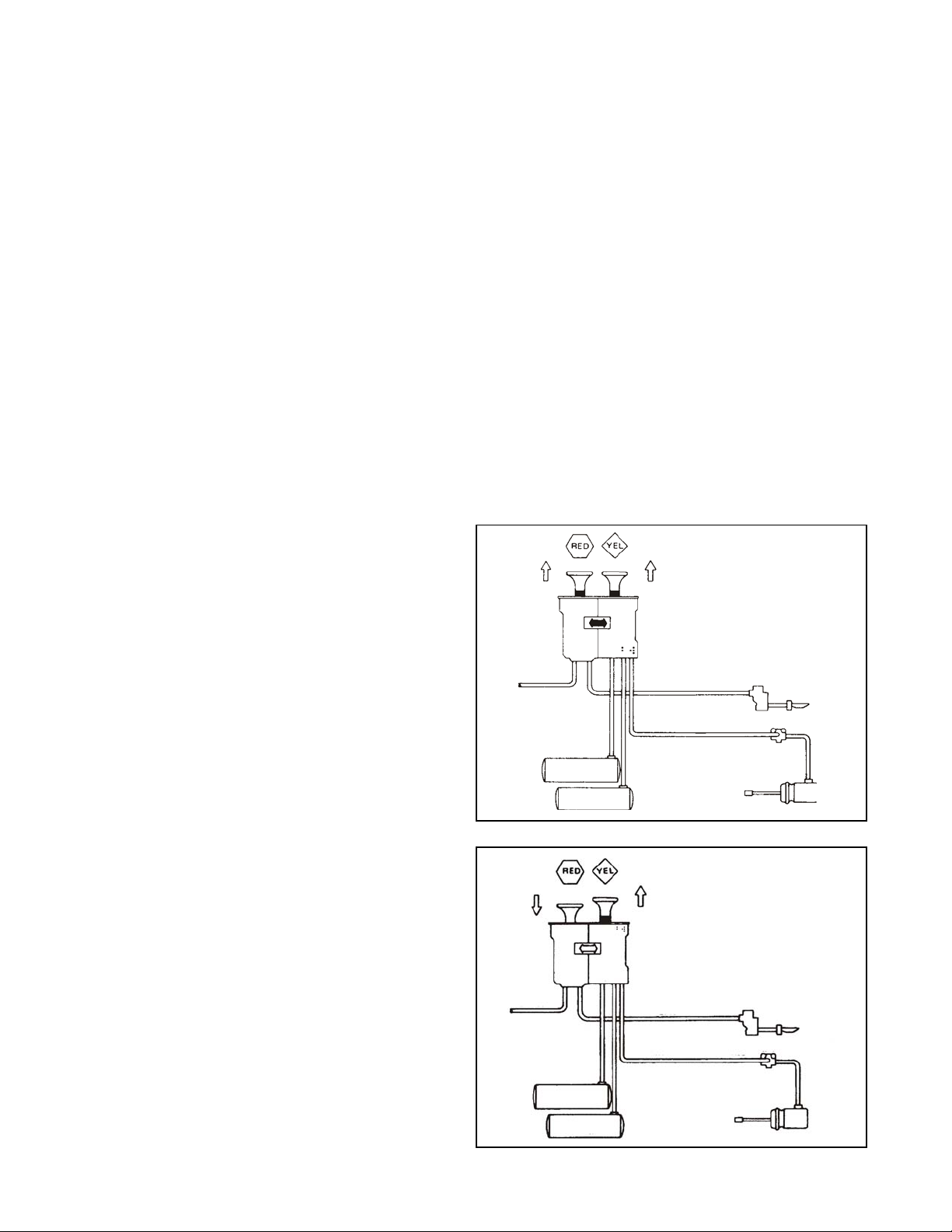
The trailer air supply valve (red button) (see Figure 1) delivers
air to the trailer supply line and also will trip (Pop out)
automatically and shut off the trailer supply if pressure
decreases to 40 ±5 P.S.I.
NOTE: Reservoir No. 1 must be the reservoir that supplies
the rear tractor axle(s).
Reservoir No. 2 must be the reservoir that supplies
the front axle.
The parking brake valve (yellow button) controls the spring
brakes on the tractor and when exhausted, simultaneously
causes the trailer supply valve to trip and exhaust, thus
applying both tractor and trailer parking brakes as required
by Federal Regulations. The trailer brakes may be
independently released by pushing only the trailer air supply
valve (red button) in.
OPERATION
Initial Charge
With the system completely discharged, both buttons are
out (Figure 4). When system pressure reaches 65 P.S.I.,
the red button (trailer supply) may be pushed in (Figure 5)
and should stay in, charging the trailer system and releasing
the trailer brakes. The yellow button may now be pushed in
which will supply air to the tractor spring brakes, releasing
them.
Normal Operating Position (Figure 7)
Automatic Application
With both buttons in, in the normal run configuration, if the
supply pressure to the push-pull valves is reduced to
40 ±5 P.S.I., the red button (trailer supply valve) must pop
out, applying the emergency or parking brakes on the trailer .
If the red button is held in manually and the pressure
decreases to 30 ±5 P.S.I., a tripper piston within the trailer
control spool will move upward, exhausting the trailer supply,
effecting the required non-override feature. The yellow (parking
brake) button will pop out at approx. 20-30 P.S.I.
PREVENTIVE MAINTENANCE
Important: Review the Bendix Warranty Policy before
performing any intrusive maintenance procedures. A warranty
may be voided if intrusive maintenance is performed during
the warranty period.
No two vehicles operate under identical conditions, as a
result, maintenance intervals may vary. Experience is a
valuable guide in determining the best maintenance interval
for air brake system components. At a minimum, the MV -2
module should be inspected every 6 months or 1500
operating hours, whichever comes first, for proper operation.
Should the MV-2™ module not meet the elements of the
operational tests noted in this document, further investigation
and service of the valve may be required.
SYSTEM PARK
™
With both buttons pushed in, air is now being supplied to
the trailer and to the tractor spring brakes; all brakes are
released.
Actuation of Trailer Park or Emergency Brakes
(Figure 6)
To actuate the trailer brakes only, the red button is pulled
out, exhausting the trailer supply line. The trailer brakes are
now applied either by air emergency or spring brakes,
depending on the type of trailer system. This mode would
be used to uncouple from the trailer and during bobtail
operation.
System Park (Figure 4)
With both buttons in for normal run modes, the parking
brakes on both tractor and trailer may be actuated by pulling
the yellow (parking brake) button out, which exhausts the
air from the tractor spring brakes and simultaneously causes
the red (trailer supply) button to pop out, applying the trailer
brakes. This complies with Federal Regulations that one
control must apply all the parking brakes on the vehicle.
Trailer Charge (Figure 5)
If both valves are out, parking the combination vehicle, and it
is desired to recharge the trailer (leaving the tractor spring
brakes applied,) the red button may be pushed in
repressurizing the trailer supply line. This mode might also
be used to park a combination vehicle with air actuated
emergency brakes on the trailer to provide demonstrated
parking capability with tractor spring brakes only .
CONTROL
FIGURE 4
MV-2
CONTROL
MODULE
EXHAUST
FIGURE 5
MV-2
MODULE
EXHAUST
™
™
SERVICE
RESERVOIR #1
SERVICE
RESERVOIR #2
SERVICE
RESERVOIR #1
SERVICE
RESERVOIR #2
SUPPLY TO TRAILER
TRACTOR SPRING BRAKE CONTROL
CHARGE TRAILER WITH
TRACTOR PARKED
TRACTOR
PROTECTION
SUPPLY TO TRAILER
TRACTOR SPRING BRAKE CONTROL
TP-3
TRACTOR
PROTECTION
VALVE
TP-3™
VALVE
™
QRV
SB-3
QRV
SB-3
2
Page 3

PARK TRAILER WITH
TRACTOR RELEASED
OR BOBTAIL TRACTOR
™
MV-2
CONTROL
MODULE
EXHAUST
SERVICE
RESERVOIR #1
SERVICE
RESERVOIR #2
SUPPLY TO TRAILER
TRACTOR SPRING BRAKE CONTROL
TP-3
TRACTOR
PROTECTION
VALVE
™
QRV
SB-3
FIGURE 6
NORMAL OPERATING
POSITION
™
MV-2
CONTROL
MODULE
EXHAUST
SERVICE
RESERVOIR #1
SERVICE
RESERVOIR #2
SUPPLY TO TRAILER
TRACTOR SPRING BRAKE CONTROL
™
TP-3
TRACTOR
PROTECTION
VALVE
QRV
SB-3
FIGURE 7
OPERATING & LEAKAGE TEST
1. Charge the air brake system to 65 P.S.I. and check for
leakage between body seals, body and cover plates.
No leakage permitted.
2. With supply pressure still at 65 P .S.I., push the red button
in. The button must stay in. Leakage at the exhaust
port must not exceed a 1" bubble in 5 seconds.
3. Develop a leak in the line delivering air to the trailer supply
circuit. The red button must pop at 40 ± 5 P.S.I. and
maintain the supply pressure. Leakage at the exhaust
port must not exceed a 1" bubble in 5 seconds.
4. Hold the red button in and again develop a leak in the
supply circuit. Air must start to escape from the exhaust
port when the trailer supply line pressure reaches
30 ±5 P.S.I.
5. Release the red button and rebuild the supply pressure
to at least 40 P .S.I. Push in the yellow button; the yellow
button must remain in. Leakage at the exhaust port should
not exceed a 1" bubble in 5 seconds.
6. Develop a leak in the tractor spring brake delivery circuit.
The yellow button must pop at 25 ±5 P .S.I. and maint ain
supply pressure. Leakage at the exhaust port should
not exceed a 1" bubble in 5 seconds.
7. Charge the system to 120 P .S.I. and push both buttons
in. Pull the red button out. The yellow button must remain
in.
8. Push the red button in and pull the yellow button out.
The red button must pop out almost instantaneously .
9. Install a gauge to monitor tractor spring brake delivery
pressure. Apply 120 P.S.I. to both reservoirs (No. 1 &
No. 2). Push in the yellow button. Delivery pressure
should equal the pressure in reservoir No. 1. Reduce
the pressure in No. 1 reservoir. Delivery pressure and
No. 1 reservoir pressure should descend together to
105-90 P .S.I. at which point the dual circuit supply valve
shuttle should switch to No. 2 reservoir and delivery
pressure should increase to No. 2 reservoir pressure.
After the No. 1 reservoir pressure is reduced to zero,
there should not be audible leakage at the No. 1 reservoir
opening. Close the leak which had been created in the
No. 1 reservoir.
10. Leaving the yellow button in, recharge the No. 2 reservoir
to 120 P.S.I. The delivery pressure should also read
120 P.S.I. Recharge the No. 1 reservoir to 100 P.S.I.
Slowly vent the No. 2 reservoir. As the No. 2 reservoir
pressure and the delivery line pressure descend,
pressure should stabilize at approx. 100 P.S.I.
11. Close all vents or leakage points and charge both
reservoirs to 120 P.S.I. Position the red button out and
the yellow button in. Develop a leak in the spring brake
delivery line and hold the yellow button in. No. 1 reservoir
pressure must reduce to zero and No. 2 reservoir
pressure to 20 - 30 P.S.I. The dual circuit supply valve
shuttle should cycle several times during this leakdown
period.
REMOVING AND REPLACING SPOOL ASSEMBLIES
Block the wheels or otherwise secure the vehicle and drain
all reservoirs. It should be unnecessary to remove the MV-2
module from the vehicle. Remove any panel, plate or whatever
is necessary to expose the valve cover plates. It is
recommended that the valve be serviced by replacing the
complete spool assemblies. The dual circuit supply valve
feature may be serviced by replacing four (4) o-rings and
one (1) spring, available in a maintenance kit.
DISASSEMBL Y - Spools (Figure 2)
1. Remove the cover plate screws. (Four in each cover)
and cover (1).
2. Carefully pull the spool assemblies out of their respective
body bores by pulling on the buttons.
3. Remove the roll pins (2) which retain the buttons on the
spool stems and remove buttons and cover plates.
™
3
Page 4

DISASSEMBL Y - Dual Circuit Supply V alve
1. The dual circuit supply valve is located in the tractor
control body. (The one from which the spool with the
yellow button has been removed.) Grasp the web in the
top of the valve spool (3) (Figure 2) with narrow nose
pliers, twist and pull valve spool out. The shuttle (4) should
also come out with the spool. Remove the shuttle return
spring (5) and o-rings (6), (7), (8) and (9).
CLEANING & INSPECTION
The non metallic components which comprise most of the
parts of the MV-2™ module should not be immersed in
any solvent type cleaner. Old lubricant should be wiped
off parts to be reused and the bores of the body wiped out
with a clean dry cloth.
ASSEMBLY - Dual Circuit Supply Valve (Figure 2)
Lubricate o-rings, bore and sliding surfaces with silicone
lubricant Bendix 291126 BW -650-M Dow Corning 55-M.
1. Place the shuttle return spring (5) in the dual circuit
supply valve bore in the body .
2. Install o-rings (6) & (7) on the shuttle (4) and (8) & (9) on
the valve spool (3).
3. Insert the small end of the shuttle in the spool and insert
the assembly into the valve bore, flush with top of body .
The dual circuit supply valve spool is retained in the body
by the same cover plate which also retains the tractor
control (yellow button) spool.
ASSEMBL Y - SPOOLS
If old spools are being used, the o-rings and all sliding
surfaces should be lubricated with Bendix BW-650-M Silicone
Lubricant (291 126). If new service replacement spools are
being installed, they will be pre-lubricated.
1. Place cover plates over each plunger stem. The cover
plates are identical and are installed convex side up.
2. Place the red button on the longer spool (for trailer air
supply), matching the groove in the button with the tongue
in the cover plate (where applicable), and secure the
button with the button roll pin. Place the yellow button
on the shorter spool (for tractor air supply), matching
button and cover (where applicable) and securing with
button roll pin as before. If new service spools are used,
a new roll pin will be found in each spool package.
3. Insert the shorter spool assembly (yellow button) in the
tractor supply bore (housing with the dual supply valve).
If the entire valve assembly has been removed, position
the assembly so that the tractor control body housing is
at 3 o’clock. With the open bore (trailer supply) at 9
o’clock, rotate the button until wording on top-center is
horizontally readable. The stepped side of the cover plate
should be covering the dual supply valve. Secure the
plate with the four flat head Phillips screws; torque to 25
inch pounds. Insert the longer spool assembly (red
button) in the remaining bore. The stepped sides of the
cover plates should key with each other when the
remaining four flat head screws are torqued to 25 inch
pounds.
BW1584 © 2004 Bendix Commercial Vehicle Systems LLC. All rights reserved. 3/2004 Printed in U.S.A.
4
SERVICE TEST
Repeat the “Operating and Leakage T est”.
WARNING! PLEASE READ AND FOLLOW
THESE INSTRUCTIONS TO AVOID
PERSONAL INJURY OR DEATH:
When working on or around a vehicle, the following
general precautions should be observed at all times.
1. Park the vehicle on a level surface, apply the
parking brakes, and always block the wheels.
Always wear safety glasses.
2. Stop the engine and remove ignition key when
working under or around the vehicle. When
working in the engine compartment, the engine
should be shut off and the ignition key should be
removed. Where circumstances require that the
engine be in operation,
be used to prevent personal injury resulting from
contact with moving, rotating, leaking, heated or
electrically charged components.
3. Do not attempt to install, remove, disassemble or
assemble a component until you have read and
thoroughly understand the recommended
procedures. Use only the proper tools and observe
all precautions pertaining to use of those tools.
4. If the work is being performed on the vehicle’s air
brake system, or any auxiliary pressurized air
systems, make certain to drain the air pressure from
all reservoirs before beginning ANY work on the
vehicle. If the vehicle is equipped with an AD-IS
air dryer system or a dryer reservoir module, be
sure to drain the purge reservoir.
5. Following the vehicle manufacturer’s
recommended procedures, deactivate the electrical
system in a manner that safely removes all
electrical power from the vehicle.
6. Never exceed manufacturer’s recommended
pressures.
7. Never connect or disconnect a hose or line
containing pressure; it may whip. Never remove a
component or plug unless you are certain all
system pressure has been depleted.
8. Use only genuine Bendix® replacement parts,
components and kits. Replacement hardware,
tubing, hose, fittings, etc. must be of equivalent
size, type and strength as original equipment and
be designed specifically for such applications and
systems.
9. Components with stripped threads or damaged
parts should be replaced rather than repaired. Do
not attempt repairs requiring machining or welding
unless specifically stated and approved by the
vehicle and component manufacturer.
10. Prior to returning the vehicle to service, make
certain all components and systems are restored to
their proper operating condition.
EXTREME CAUTION should
™
 Loading...