

Page 1
®
Bendix® Gen 4™ and Gen 5™ ABS for Trucks, Tractors, and Buses
SD-13-4746
Cab-Mounted Models
GEN 4™ AND GEN 5™ ABS INTRODUCTION
This manual describes both the cab mount and the frame
mount versions of the Bendix® Gen 4™ and Gen 5™ Antilock
Brake System/Automatic Traction Control (ABS/ATC)
systems.
Both cab and frame mount versions are designed for:
• Tractors
• Trucks
• Buses and
• Motor Coaches and
• RVs.
This manual covers:
• ABS/A TC Operation
• System Components
• Service Procedures
• Diagnosis and
• Troubleshooting Procedures.
For information on disassembly , installation, and service of
related axle and brake components, refer to their individual
Bendix Service Manuals.
For assistance in your area call Bendix at 1-800-247-2725
or RoadRanger® at 1-800-826-4357.
These ABS controllers and systems were originally
marketed by Eaton Corporation under the Eaton® brand
name. For more information contact Bendix, your local
authorized Bendix dealer, or RoadRanger®.
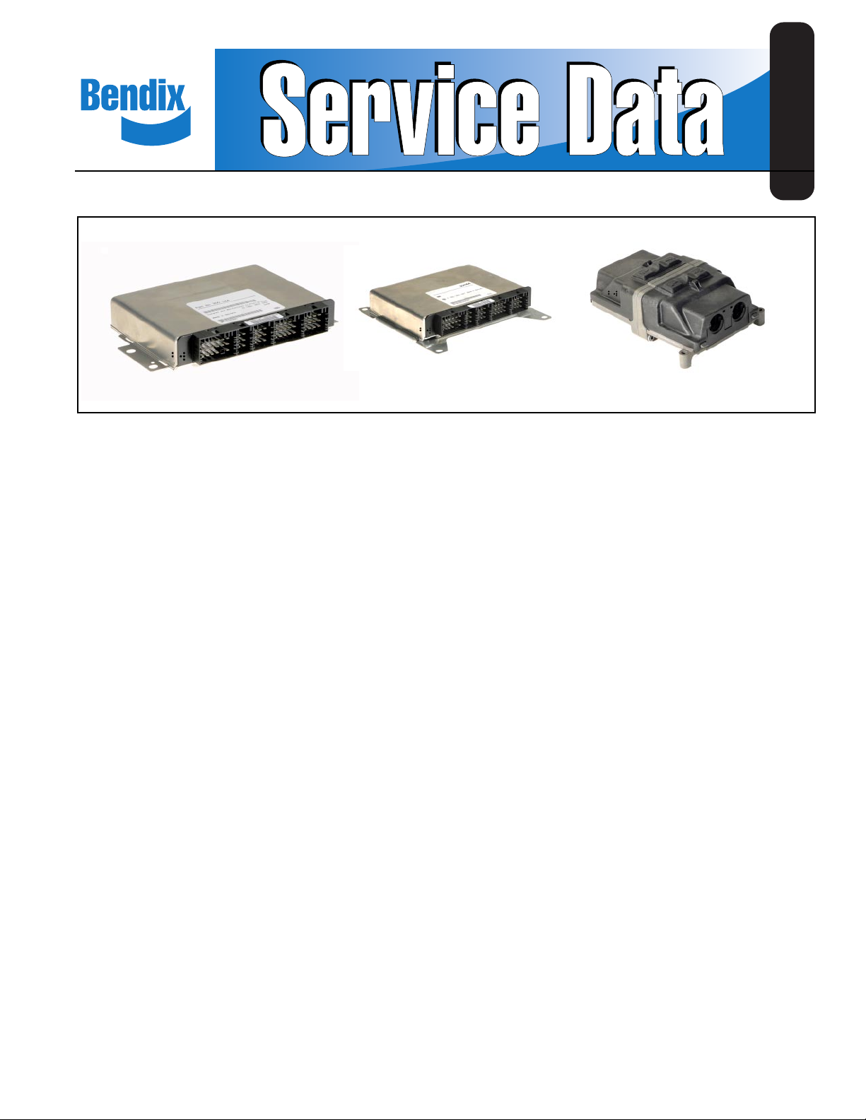
Frame-Mounted Model
FIGURE 1 - Bendix® ABS Controller Assemblies
Table of Contents
ABS Operation . . . . . . . . . . . . . . . . . . . . . . . . . . . . . . . 2
ABS Component Function . . . . . . . . . . . . . . . . . . . . . . 3
ABS Indicator Lamp . . . . . . . . . . . . . . . . . . . . . . . . . . . 3
ABS Trailer Indicator Lamp . . . . . . . . . . . . . . . . . . . . . 3
Automatic Traction Control (ATC) System . . . . . . . . . . 4
Component Overview . . . . . . . . . . . . . . . . . . . . . . . . . 5
Electronic Control Units (ECUs) . . . . . . . . . . . . . . . . . 7
ABS Valves . . . . . . . . . . . . . . . . . . . . . . . . . . . . . . . . . 9
Modulator Valve Operation Modes . . . . . . . . . . . . . . . 10
Optional Front Axle Modules . . . . . . . . . . . . . . . . . . . 11
Diagnostics . . . . . . . . . . . . . . . . . . . . . . . . . . . . . . . . 13
Troubleshooting Procedures . . . . . . . . . . . . . . . . . . . 13
System Configurations . . . . . . . . . . . . . . . . . . . . . . . 15
ServiceRanger PC Software . . . . . . . . . . . . . . . . . . . 16
Test Equipment . . . . . . . . . . . . . . . . . . . . . . . . . . . . . 16
Reading Configuration Codes . . . . . . . . . . . . . . . . . . 18
Retrieving Diagnostic Trouble Codes . . . . . . . . . . . . . 18
Clearing Diagnostic Trouble Codes and/or System
Configuration . . . . . . . . . . . . . . . . . . . . . . . . . . . . . 20
Disabling ATC for Dyno Testing . . . . . . . . . . . . . . . . . 20
Speed Sensor Troubleshooting . . . . . . . . . . . . . . . . . 25
The 17•12 Sensor Memory Diagnostic Trouble Code 26
Wheel End Speed Sensor Repair . . . . . . . . . . . . . . . 28
Pressure Modulator V alve (PMV) T roubleshooting . . 30
ABS Modulator Valve . . . . . . . . . . . . . . . . . . . . . . . . . 33
Automatic Traction Control (ATC) V alve
Troubleshooting . . . . . . . . . . . . . . . . . . . . . . . . . . . 34
Performance Test of the Relay Valve . . . . . . . . . . . . . 34
ATC Valve Removal . . . . . . . . . . . . . . . . . . . . . . . . . . 36
Cab Mount ECU Pin Identification . . . . . . . . . . . . . . . 39
Frame Mount ECU Pin Identification . . . . . . . . . . . . . 43
Document Revision Level
This document is subject to revision.
For updates, please visit www.bendix.com.
Eaton®, RoadRanger®, and ServiceRanger® are registered
trademarks of Eaton Corporation.
1
Page 2
ANTILOCK BRAKING SYSTEM (ABS)
ABS-controlled braking ensures optimum vehicle stability
while minimizing the stopping distance. During vehicle
operation, the ABS Electronic Control Unit (ECU)
continuously monitors all wheel speed sensors. Data input
from the wheel speed sensors allows the ECU to:
• Detect impending wheel lock.
• Maintain optimum wheel slip during braking.
• Maximize vehicle stability while maintaining braking
effectiveness.
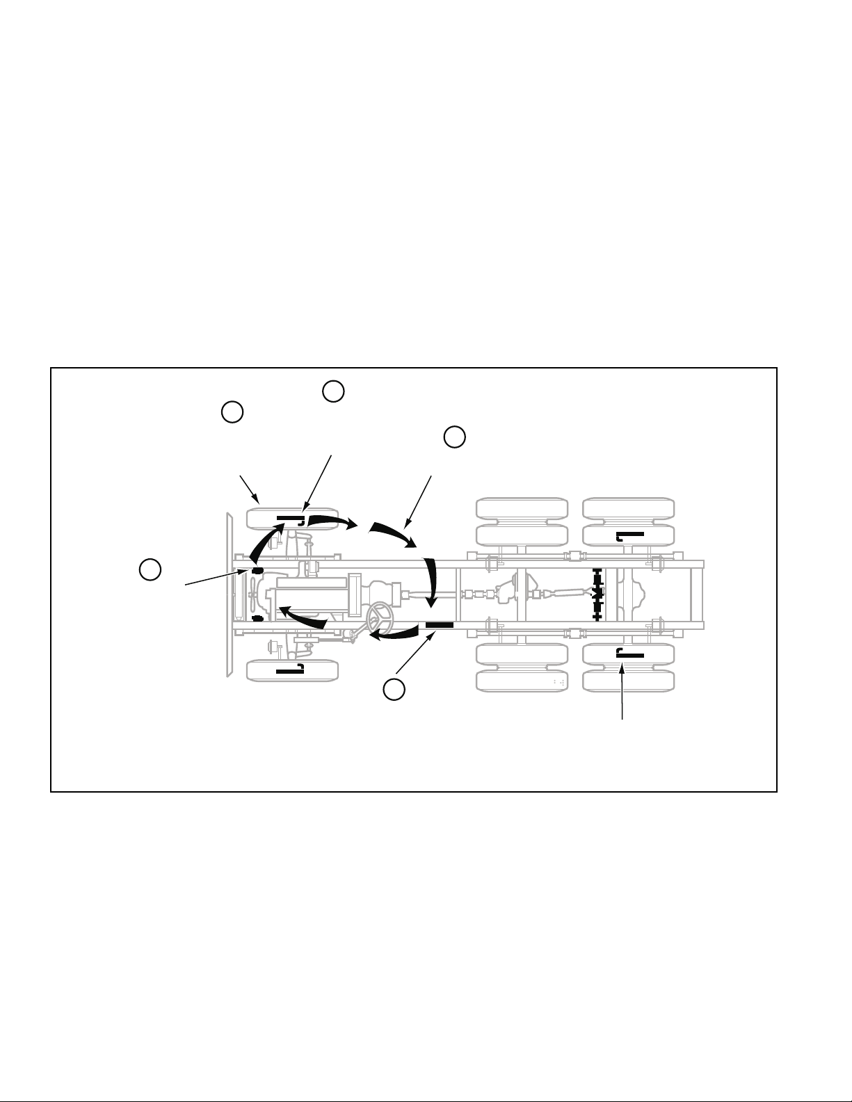
ABS Operation
The ABS controls braking by operating the Pressure
Modulator V alves. The ECU makes a new assessment of
conditions and updates the control signal to the pressure
modulator valves at the rate of 100 times per second.
1
5
Braking force
remains at
optimum level
Speed sensors
monitor wheel
rotation
When inactive, the pressure modulator valves provide
straight-through-passages for supply air to the brake
chambers. During ABS operation (an ABS “event”), the
control unit operates the valves to override the supply of
air to the chambers. During an ABS release, supply air is
held off while the chambers are vented to the atmosphere.
In hold mode, supply air is held off and chamber air is held
constant. When required, air is applied to the chamber at
a controlled rate by modulating the hold side of the
modulator valve.
The ABS system itself does not apply additional braking
power. Rather , the purpose of ABS is to limit brake torque
to prevent locking that results in loss of lateral stability and
increased stopping distances. Cautious driving practices
such as maintaining adequate distances from the vehicle
ahead are still essential to safe vehicle operation.
2
Speed signal
to ECU
4
Hold and release
solenoids control
air pressure inthe
brake chambers
FIGURE 2 - Overview of ABS Operation
3
Electronic Control Unit(ECU)
interprets speed signals
and activates valves
Sensors on
all configured wheels
signal status toECU
2
Page 3

ABS Component Function
The ABS system operates as follows (see Figure 2).
1. Speed sensors on each wheel monitor wheel rotation.
2. Each speed sensor communicates wheel rotation pulses
to the central Electronic Control Unit (ECU).
3. The ECU receives speed sensor input, interprets the
signal pulses, and calculates speed and acceleration
rates for the wheels and the vehicle.
4. Based on speed sensor input with the brakes applied,
the ECU detects impending wheel lock and operates
the ABS modulator valves as required for proper control.
The modulator valves can be operated in either a release
or a hold mode to regulate air pressure in the brake
chambers.
5. Braking force is applied at a level which minimizes
stopping distance while maintaining as much lateral
stability as possible.
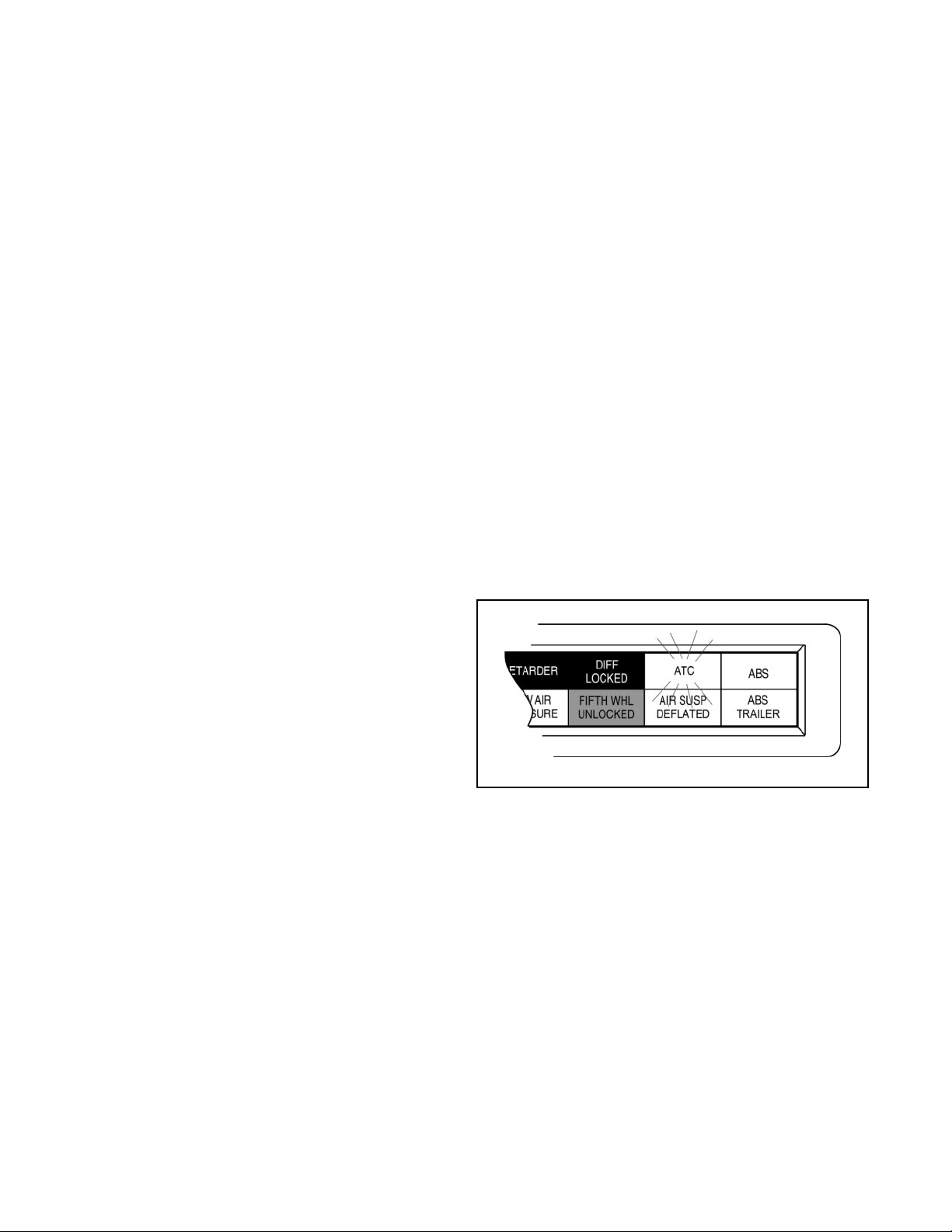
FIGURE 3 - ABS Indicator Lamps
ABS Indicator Lamp
This lamp is the primary indicator of the ABS status.
• The ABS lamp illuminates steadily for a two second
bulb-check whenever the switched ignition is ON. The
ABS lamp turns OFF after the bulb-check if there are
no ABS malfunctions present.
• The ABS lamp flashes on and off continuously when
the off-highway mode is selected. (Special option for
military and off-highway vehicles.)
• If the Indicator Lamp remains ON, after the bulb-check,
there is an ABS diagnostic trouble code that requires
service.
NOTE: In the case of a speed sensor failure which has
been corrected, the indicator lamp will remain on until
sensor output has been verified by the control unit. In this
case it is necessary to move the vehicle above 5 mph before
the indicator lamp will turn off.
ABS Trailer Indicator Lamp
Tractor/Towing vehicles manufactured on or after March 1,
2001 are equipped with a cab mounted “ABS Trailer”
indicator lamp.
When an ABS equipped trailer with Power Line Carrier
(PLC) communications capability is connected to the tractor ,
the ABS T railer indicator lamp will illuminate for a two second
bulb check after the ignition is switched on. The ABS lamp
turns OFF after the bulb-check if there are no ABS
malfunctions present on the trailer ABS.
If the trailer is NOT equipped with ABS or ABS with PLC
capability , the ABS trailer indicator lamp in the cab will not
illuminate.
3
Page 4
Automatic Traction Control (ATC) System
The ATC system is available on all Standard ABS ECU’s.
ATC is not availa ble on Basic ECU’s. It helps improve
traction on slippery or unstable driving surfaces by
preventing excessive wheel spin. ATC also enhances
vehicle stability by prevention of power spin-out.
A TC requires:
1. ATC valve - Either a stand alone valve or a Rear Axle
V alve Assembly with integral A TC solenoid may be used.
2. SAE J1922 or J1939 engine interface (the ABS ECU
serial data interface must match the engine controller
interface).
3. Brake Light Switch input.
4. ATC Indicator Lamp.
The Electronic Control Unit (ECU) must be configured for
ATC operation either by using the diagnostic switch, an
MPSI ProLink
®
hand-held tester or Eaton’s ServiceRanger
PC software.
A TC Operation
During periods of wheel slip, the Electronic Control Unit
enters an Automatic Traction Control mode. There are
various modes of Automatic Traction Control.
Thermal (Brake Heat) Protection
T o prevent excessive brake and drum temperature resulting
from brake activity , A TC incorporates a brake temperature
estimation algorithm to determine when differential braking
mode should be suspended. The differential braking
function is re-enabled after a cool-down period.
A TC Indicator Lamp
The ATC indicator lamp operates when a vehicle is
equipped with the optional Automatic T raction System.
• Gen 4™ ABS – Lights at key-ON and remains lit with
A TC inactive until the driver presses the brake pedal.
• Gen 5™ ABS – Light s at key-ON and turns of f af ter a 2
second lamp check. A TC is active after the lamp check.
• Flashes rapidly to indicate that ATC is active.
• Flashes slowly when the “mud-and-snow” mode is
selected and then flashes more rapidly when the
automatic traction control system operates.
• Remains ON if an engine data link failure occurs.
NOTE: Some non-ATC equipped vehicles have an ATC
lamp that is labeled as a spin light. It indicates when a low
traction condition has been encountered. No control action
is taken.
System operation:
• At speeds above 25 mph, the engine is throttled back
via the SAE J1922 or SAE J1939 data link to control
spin out.
• At speeds below 25 mph, both engine control and
differential brake control are activated as required to
control wheel slip. Once triggered, differential braking
mode remains active regardless of vehicle speed.
• An optional mud and snow switch allows greater wheel
spin (more torque) when activated. It is intended for
adverse conditions, usually off-highway. Except for
special cases, the switch is programmed for momentary
operation. ATC reverts to normal operation when the
switch is cycled a second time and whenever the system
goes through a power-up cycle.
Component Function
When brake control is utilized, the ATC valve is activated,
diverting supply tank air to the Modulator Valves on the
drive axle(s). The Electronic Control Unit then activates
the appropriate solenoids in order to apply a brake force to
the spinning wheel. The Automatic Traction Control System
cannot increase traction to a particular wheel; it can only
utilize the available traction.
FIGURE 4 - ATC Indicator Lamp
4
Page 5

Component Overview
Bendix ABS components include:
• Electronic Control Unit (ECU): The ECU monitors
and controls the ABS. It also diagnoses ABS
malfunctions and stores specific diagnostic trouble
codes.
• Pressure Modulator Valve (PMV): This
component regulates brake chamber air pressure. It
houses the hold and release solenoids. A modulator
valve is located near each brake chamber or pair of
brake chambers that make up an ABS controlled wheel
site.
• Rear Axle V alve Assembly: An assembly made up of
two pressure modulator valves and a relay valve.
• Wheel End Speed Sensor: Single point variable
reluctance (magnetic) sensor that generates an
alternating voltage signal in response to the movement
of teeth on a tone wheel.
• ABS Lamp (Yellow): This indicator lamp, located on
the driver instrument panel, warns the driver of ABS
malfunctions. It is also capable of blinking diagnostic
fault codes when the ECU is in the self-diagnostic mode.
• In-Cab ABS Trailer Lamp: This indicator lamp, located
on the driver instrument panel, warns the driver of trailer
ABS malfunctions. It is not capable of blinking
diagnostic trouble codes.
• A TC Valve: The traction control valve applies full system
pressure to the relay valve during traction control
operation to provide differential (side to side) braking
at controlled drive axles.
• ATC Lamp: This indicator lamp, located on the driver
instrument panel, lights to indicate loss of traction which
is being managed by the Automatic Traction Control
System.
• Relay/Breaker Panel: The OEM provides two circuit
breakers and either one or two relays as part of the
ABS. One relay is used for indicator lamp control. A
second (optional) relay may be used to control a retarder
and/or lockup torque converter.
• Diagnostic Port Connector: The diagnostic port
connector is an industry standard connector that is used
to connect to the J1587 diagnostic link. This connector
also provides power and ground for diagnostic test
equipment.
5
Page 6
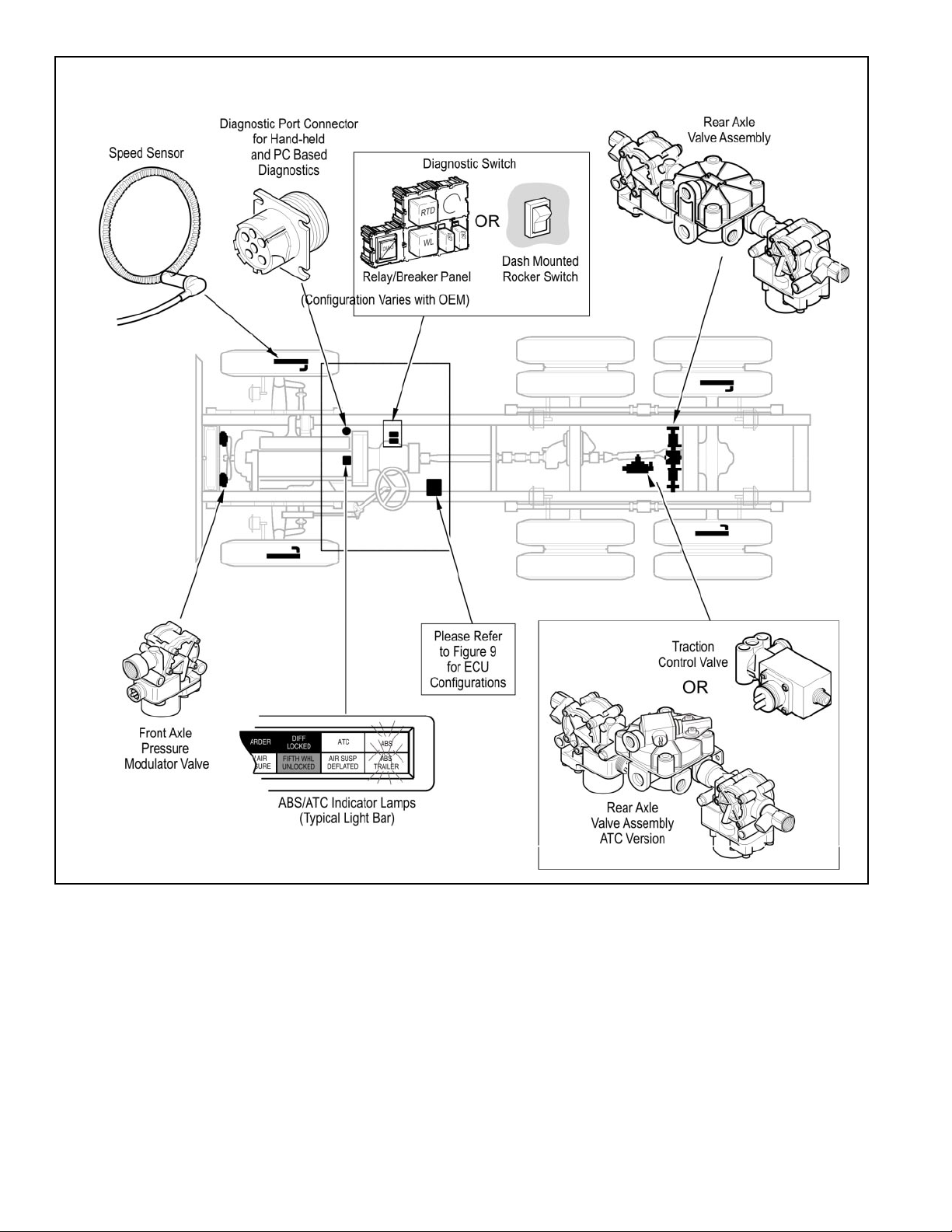
FIGURE 5 - ABS Components
6
Page 7
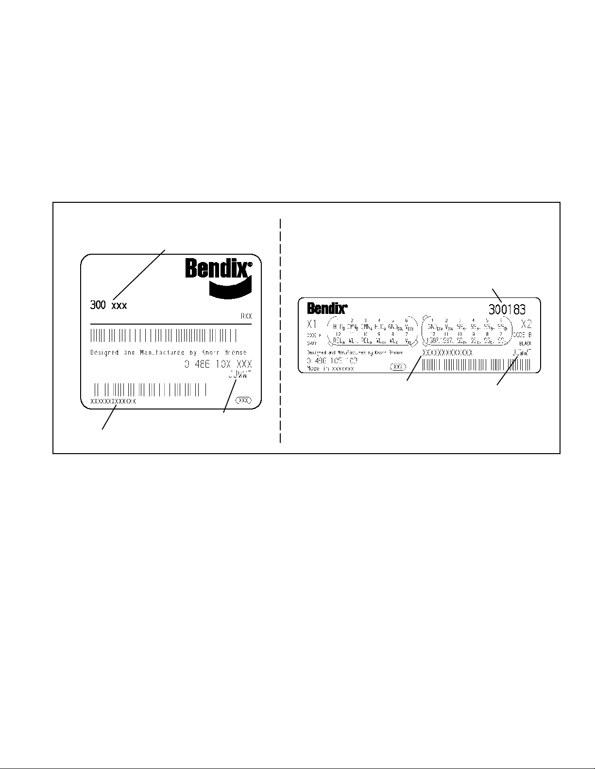
Electronic Control Units (ECUs)
Identification
Frame mount ECUs are environmentally packaged versions
of the related Gen 4™ & Gen 5™ ABS cab-mounted units
(Standard, Basic). The circuitry and software is the same.
™
Gen 5
hardware. ECUs are available in 4 and 6-channel versions
with either J1922 or J1939 data links. There is also a 24volt version. Further service information is available on
www.bendix.com.
ABS units incorporate power line carrier (PLC)
Bendix Part Number
Bendix Part Number
Date Code
Serial Number
FIGURE 6 - Electronic Control Unit Identification Tags
Cab Mount
Serial Number
Frame Mount
Date Code
7
Page 8
300XXX
Designedand Manufacturedby
0 486 104 036 Made inGermany
MFOEO798O313
™™
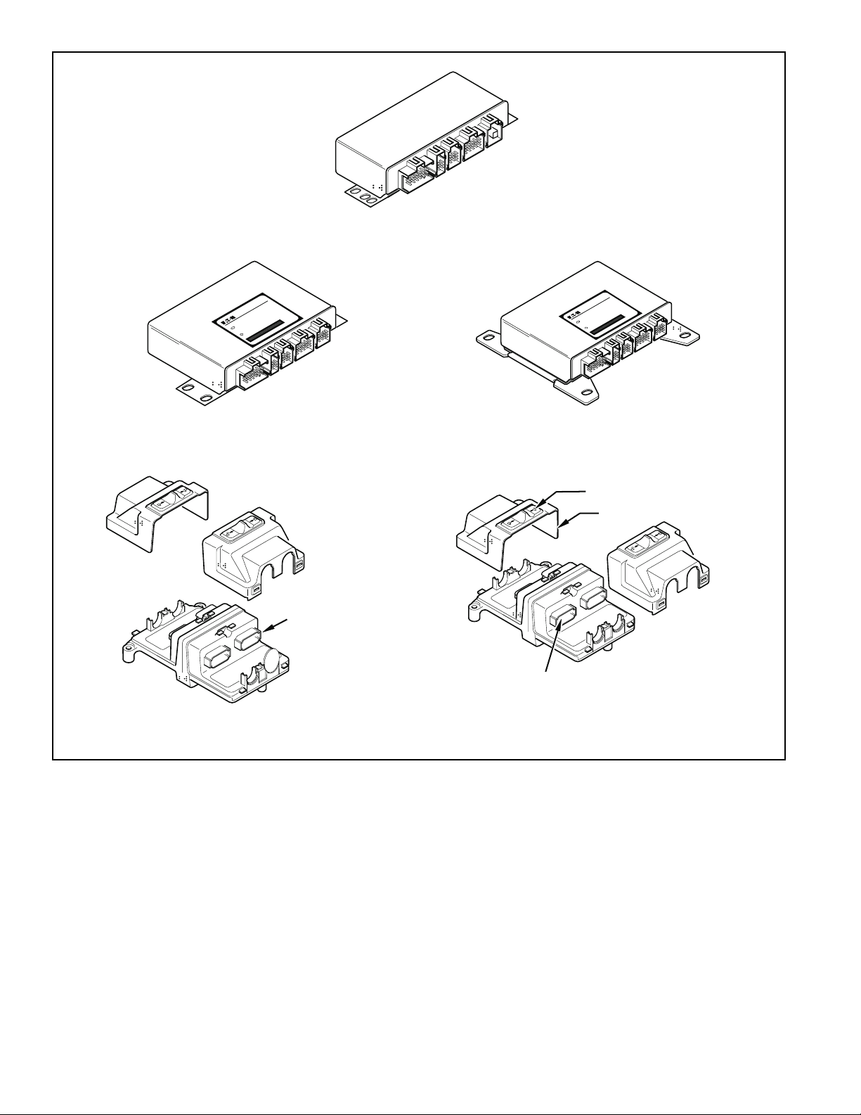
Gen 4 & Gen 5 ABS - Basic Cab Mount
BOSCH
862
300XXX
ndManufacturedby
Designeda
0 486 104 036 MadeinGermany
MFOEO798O
BOSCH
862
313
™
Gen 5 ABS– Standard Cab Mount
Blank
Connector
™
Gen 5 ABS(PLC - Basic Frame Mount)
FIGURE 7 - Available Bendix ABS Electronic Control Units
™
Gen 4 ABS– Standard Cab Mount
Sliding Lock
ECU Cover
ECU Connector
(1 of4)
™™
Gen 4 & Gen 5 ABS – Standard Frame Mount
8
Page 9
ABS Valves
The ABS modulator valve controls air pressure to individual
brake assemblies. Depending on the particular ABS
configuration, a system may utilize three, four or six
modulator valves. See Figure 8.
Each modulator valve contains two air control solenoids,
which act as pilots to the hold and release diaphragms.
The hold solenoid blocks inlet air to brake chambers; the
release solenoid removes pressure from the brake. The
3-pin threaded connector has pins for the hold and release
solenoid and a third, common terminal.
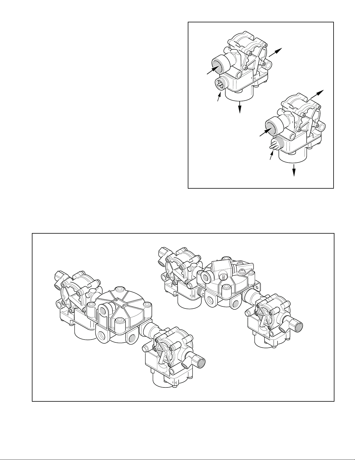
Rear Axle Valve Assemblies
Rear Axle Valve Assemblies are available for some
applications depending on OEM preferences. They are
combinations of two modulator valves and a relay valve.
The assemblies are available in 4.0 and 5.5 PSIG versions,
with or without an integral ATC solenoid.
1/2 NPT
Inlet Port
Twist-Lock
Connector
Exhaust Port
1/2 NPT
Inlet Port
FIGURE 8 - Modulator Valve
1/2 NPT
Delivery Port
1/2 NPT
Delivery Port
Threaded
Connector
Exhaust Port
ATCVersion
Standard Version
FIGURE 9 - Rear Axle Valve Assemblies, 4-Port ABS and ABS/ATC Versions Shown
9
Page 10
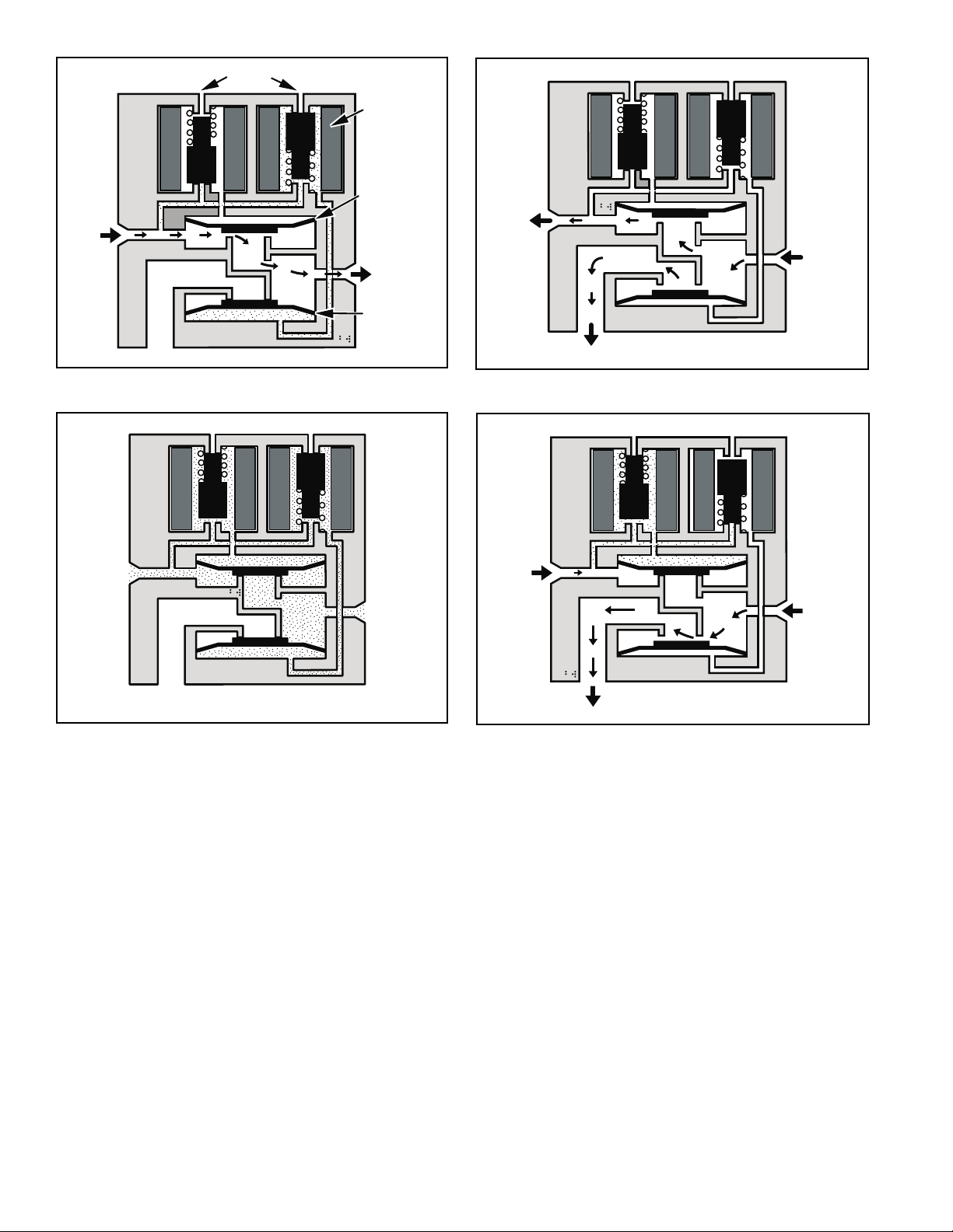
Vents
Solenoid
Inlet
Exhaust
FIGURE 10 - Normal Apply and ABS/ATC Apply
Inlet
Hold
Diaphragm
Outlet
Release
Diaphragm
Outlet
Inlet
Zero
Pressure
Outlet
Exhaust
FIGURE 11 - Normal Release
Inlet
Outlet
Exhaust
FIGURE 12 - ABS/ATC Hold
Modulator Valve Operation Modes
1. Apply–Air flows straight through valve. Hold diaphragm
is vented to allow air flow. Inlet pressure feeds behind
release diaphragm to block the exhaust port. No
solenoids are activated.
2. Normal Release–With quick release function, hold
diaphragm is vented and there is no pressure at the
inlet port. Air is allowed to flow from outlet to inlet. Since
release diaphragm is not pressurized, air also flows out
the exhaust port. No solenoids are activated.
Exhaust
FIGURE 13 - ABS/ATC Release
3. ABS/ATC Hold–The hold solenoid is activated. Both
diaphragms are pressurized. No air flows through the
valve.
4. ABS/ATC Release–Both solenoids are activated. The
hold diaphragm is pressurized, blocking the inlet air.
The release diaphragm is vented, allowing air to flow
from the outlet port back through the exhaust port.
10
Page 11
Optional Front Axle Modules
An optional front axle module is available. It is an assembly
of two modulator valves and a quick release valve. Three
crack pressure settings are available:
• 0-1 PSIG
• 3-4 PSIG
• 6-8 PSIG.
FIGURE 14 - Front Axle Module
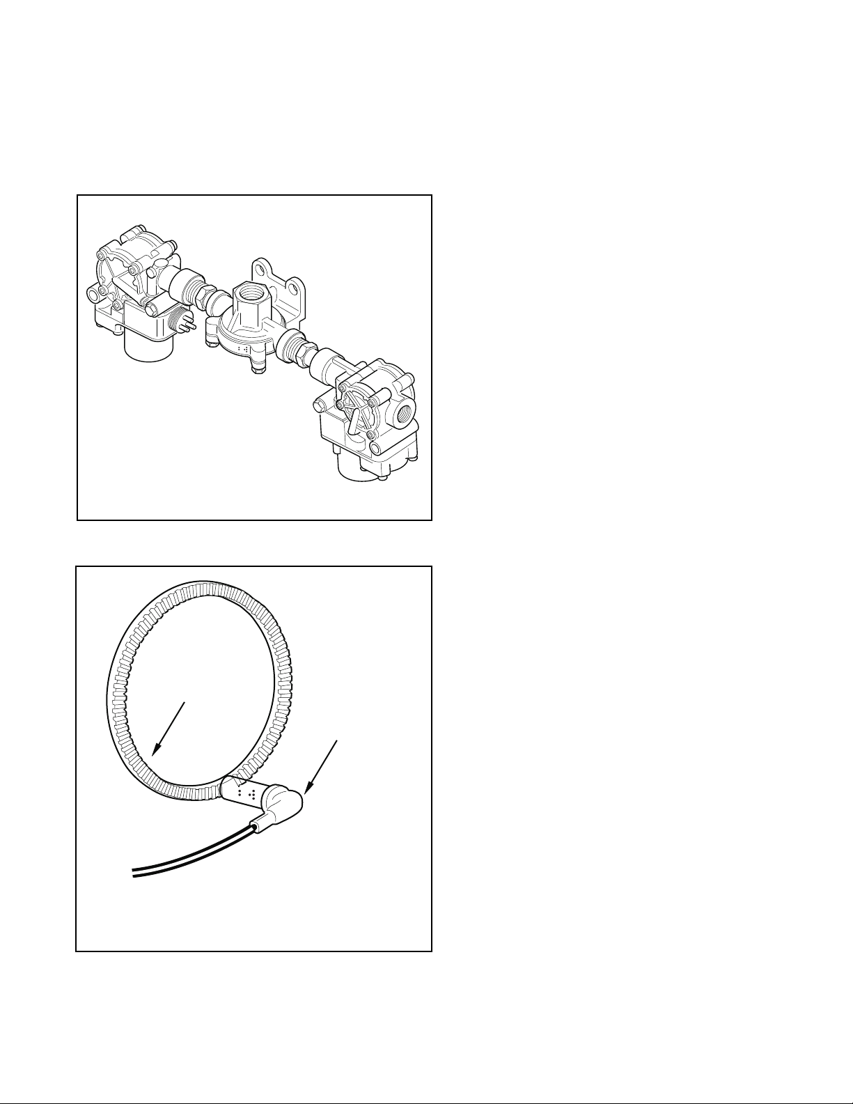
Tone
Ring
Speed Sensors
Each wheel of an axle under direct ABS control is monitored
by a speed sensor. S peed sensors for drive axles and steer
axles may be different styles and installed in different
locations.
Wheel End Sensors
For most applications, Bendix ABS uses standard wheel
end sensors (see figure 15). The front sensor is accessible
on the inboard side of the steering knuckle. The rear drive
axle sensor is accessible by removing the wheel and drum
assembly.
Wheel-end sensors are conventional, single point, variable
reluctance sensors. These are often referred to as
"magnetic sensors" or "magnetic pickups." These sensors
consist of a rod or pole piece surrounded by a coil of wire.
A magnet is closely coupled to the pole piece and circulates
a magnetic field through the coil. As the teeth of the tone
ring rotate past the pole piece, the resistance (reluct ance)
to the magnetic field varies. The variable reluctance causes
variations in the magnetic field which in turn induce a varying
voltage in the coils which are wound around the pole piece.
Some general characteristics of variable reluctance,
magnetic sensors are:
• The output voltage decreases as the air
gap increases.
• The output voltage increases with the speed of the teeth
past the pole piece.
• The output voltage waveform is independent of the
direction of wheel rotation.
Wheel-End Sensors are protected with stainless steel metal
sheaths. They are designed to fit within beryllium-copper
friction sleeves which give them a self-adjustment feature.
Wheel End Speed Sensor
Drive and Steer Axles
Right angle version shown
Straight version also available
FIGURE 15 - Sensor Assembly
Wheel End
Sensor
Standard
11
Page 12
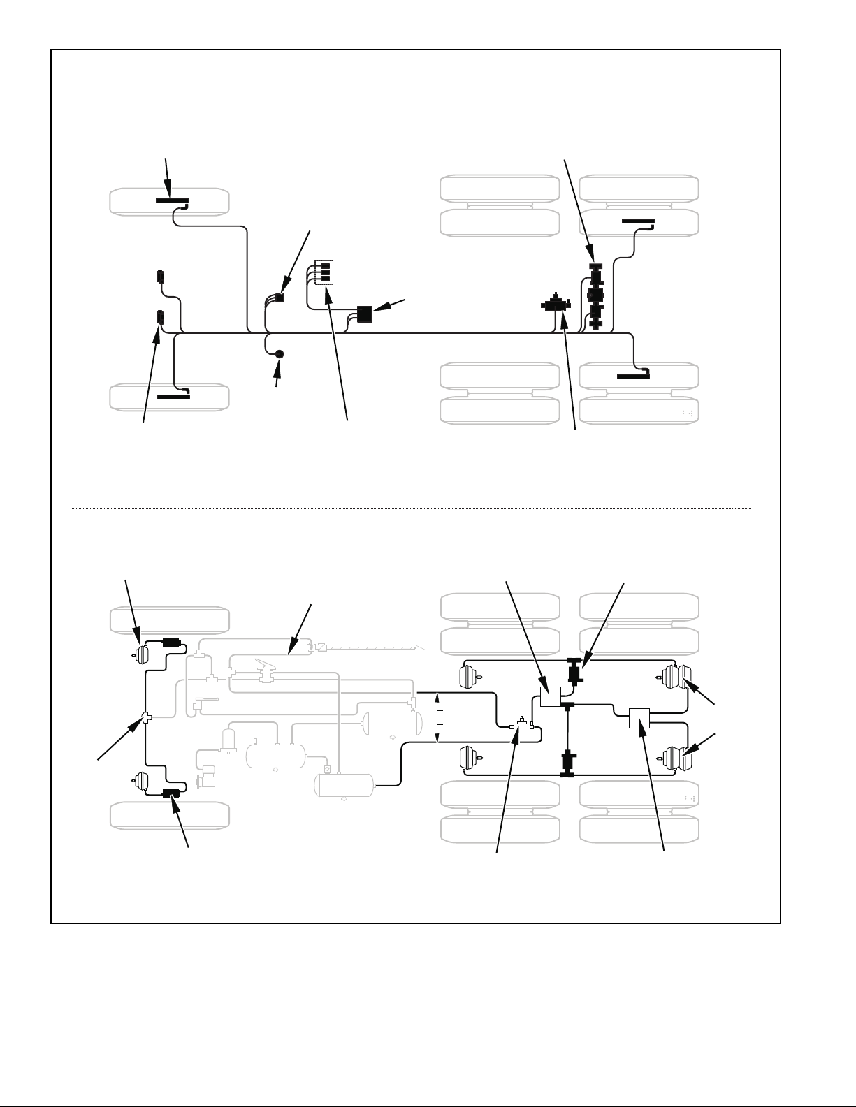
Speed Sensor
FrontAxle
Pressure
Modulator Valve
Electrical Layout
Indicator Lamps
ABS TractorIndicator Lamp (IL)
ABS TrailerIL (after 3/1/01)
ATCLamp (whenATC equipped)
Electronic Control
Diagnostic
Connector
Diagnostic Switch
ABS OffRoadSwitch (optional)
ATCMud & Snow Switch (optional)
RearAxle
ValveAssembly
Unit (ECU)
Cab Mountor
Frame Mount
TractionControlValve
StandAlone or Integral with
RearAxle ValveAssembly
Pneumatic Layout
Brake
Chamber
Treadle
Quick
Release
Valve
SteerAxle
Modulator Valve
FIGURE 16 - Typical Electrical and Pneumatic Layouts
Relay Valve
Control
Supply
ATCValve
Pressure ModulatorValve
Brake
Chambers
Anti-Compounding
Relay /Quick
Release Valve
12
Page 13

DIAGNOSTICS
An important feature of Bendix ABS is the system diagnostic
capability. This section describes how to retrieve
configuration information and error codes to troubleshoot
ABS system diagnostic trouble codes. There are three ways
to retrieve and display ABS configuration information and
trouble codes:
• ServiceRanger PC software: Displays configuration
information and diagnostic trouble codes on the PC
monitor. Refer to the ServiceRanger PC software
information later in this section.
• ProLink hand-held tester: Displays configuration
information and diagnostic trouble codes on the handheld tester display. Refer to the hand-held tester
information later in this section.
• Diagnostic switch: Flashes configuration code and
diagnostic trouble codes on the ABS indicator lamp.
Refer to page 18 for operation of the diagnostic switch.
Fault Codes
WARNING! PLEASE READ AND FOLLOW
THESE INSTRUCTIONS TO AVOID
PERSONAL INJURY OR DEATH:
When working on or around a vehicle, the following
general precautions should be observed at all times.
1. Park the vehicle on a level surface, apply the
parking brakes, and always block the wheels.
Always wear safety glasses.
2. Stop the engine and remove ignition key when
working under or around the vehicle. When
working in the engine compartment, the engine
should be shut off and the ignition key should be
removed. Where circumstances require that the
engine be in operation, EXTREME CAUTION should
be used to prevent personal injury resulting from
contact with moving, rotating, leaking, heated or
electrically charged components.
3. Do not attempt to install, remove, disassemble or
assemble a component until you have read and
thoroughly understand the recommended
procedures. Use only the proper tools and observe
all precautions pertaining to u se of those tools.
4. If the work is being performed on the vehicle’s air
brake system, or any auxiliary pressurized air
systems, make certain to drain the air pressure
from all reservoirs before beginning ANY work on
the vehicle. If the vehicle is equipped with an
AD-IS™ air dryer system or a dryer reservoir module,
be sure to drain the purge reservoir.
5. Following the vehicle manufacturer’s
recommended procedures, deactivate the electrical
system in a manner that safely removes all
electrical power from the vehicle.
6. Never exceed manufacturer’s recommended
pressures.
7. Never connect or disconnect a hose or line
containing pressure; it may whip. Never remove a
component or plug unless you are certain all
system pressure has been depleted.
8. Use only genuine Bendix® replacement parts,
components and kits. Replacement hardware,
tubing, hose, fittings, etc. must be of equivalent
size, type and strength as original equipment and
be designed specifically for such applications and
systems.
9. Components with stripped threads or damaged
part s should be replaced rather than repaired. Do
not attempt repairs requiring machining or welding
unless specifically stated and approved by the
vehicle and component manufacturer.
10. Prior to returning the vehicle to service, make
certain all components and systems are restored
to their proper operating condition.
11. For vehicles with Antilock Traction C ontrol (ATC),
the ATC function must be disabled (ATC indicator
lamp should be ON) prior to performing any vehicle
maintenance where one or more wheels on a drive
axle are lifted off the ground and moving.
Troubleshooting Procedures
Figure 17 shows an organized approach to troubleshooting
ABS trouble codes. Follow the steps listed below to locate
and correct ABS component and wiring problems.
1. Check that the ABS ECU configuration corresponds to
the ABS components installed on the vehicle.
Reconfigure the ECU if the configuration does not match
the installed ABS components.
2. Access active diagnostic trouble code(s). Inactive
(historical) diagnostic trouble codes are also reported
and may provide additional information to aid in
troubleshooting.
3. Look up the code description, the possible causes and
the repair procedures provided in this section.
4. Perform the recommended repair procedures.
5. After the repairs are completed, clear all codes and
check for any additional codes.
13
Page 14
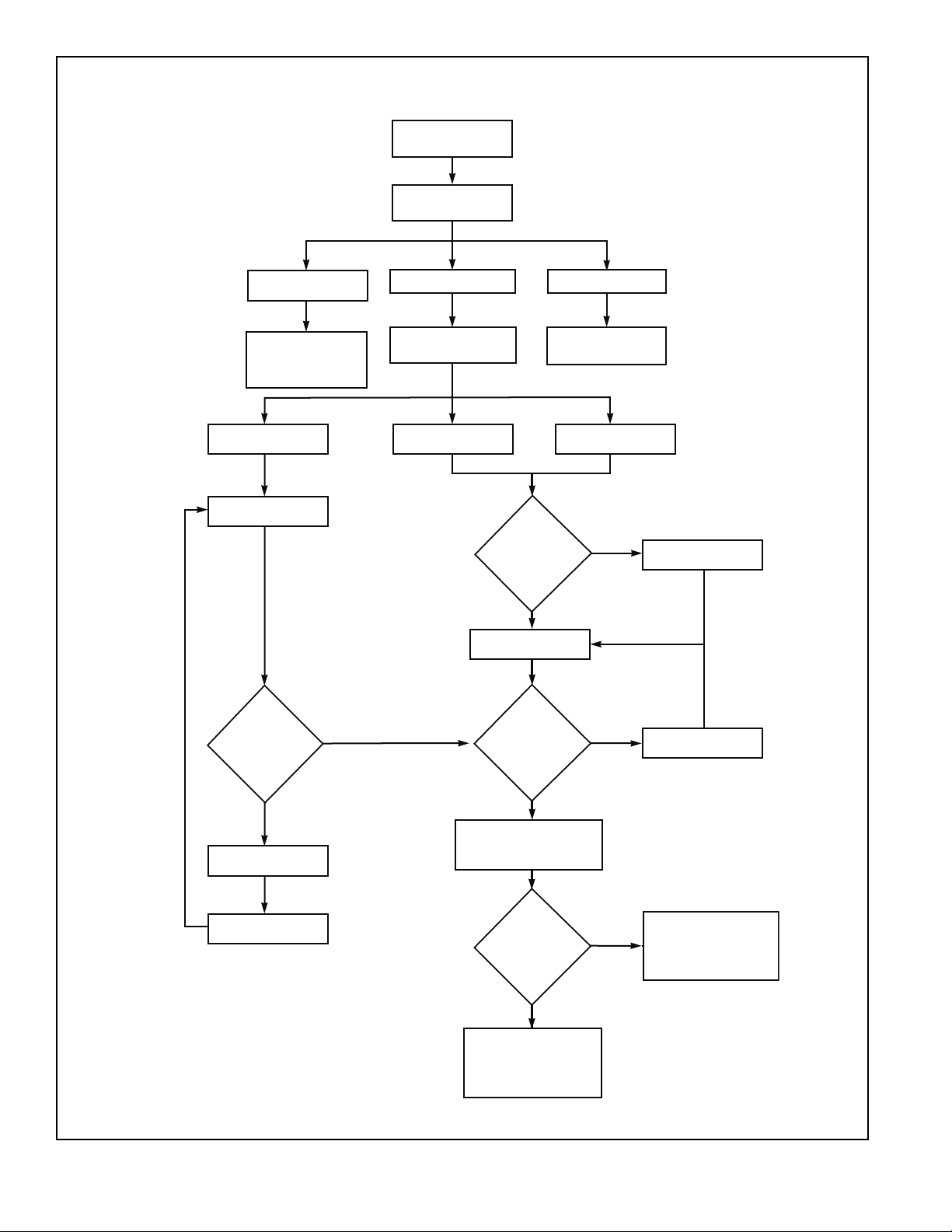
Cycle ignition key
OFF to ON
ObserveABS
indicator lamp operation
Lamp turns OFF after
2 second lamp check
ABS system not reporting
Codes–perform traditional
foundation brake
troubleshooting and repair
Activate blink codes
with diagnostic button
Check ECU configuration
Indicator lamp
blinking when activated
with diagnostic
button?
YES
Lamp stays ON
Select EatonABS diagnostic tool
Use Service Ranger
diagnostic software
Check ECU configuration
Does tester
communicate with
ECU?
YES
Does configuration
information agree
with available
hardware?
Lamp never ON
Check for power to ABS ECU.
Check indicator lamp and wiring
Use MPSI
ProLink tool
NO
NO
Check J1587 data link wiring
Reconfigure ECU
NO
Check power circuit
for ECU
Reconfigure ECU
FIGURE 17 - Antilock Brake System Troubleshooting Chart
14
YES
Read trouble codes and descriptions
Takecorrectiveaction
Clear active and inactive trouble codes
Is this a trailer
ECU?
NO
Recheck trouble codes after clearing.
If indicator lamp remains lit
and 17-12 trouble code is set,
drive vehicle to clear and turnoff
indicator lamp.
YES
Recheck trouble codes after clearing.
If indicator lamp remains lit
and no trouble codes are set,
drive vehicle to turn off
indicator lamp.
Page 15
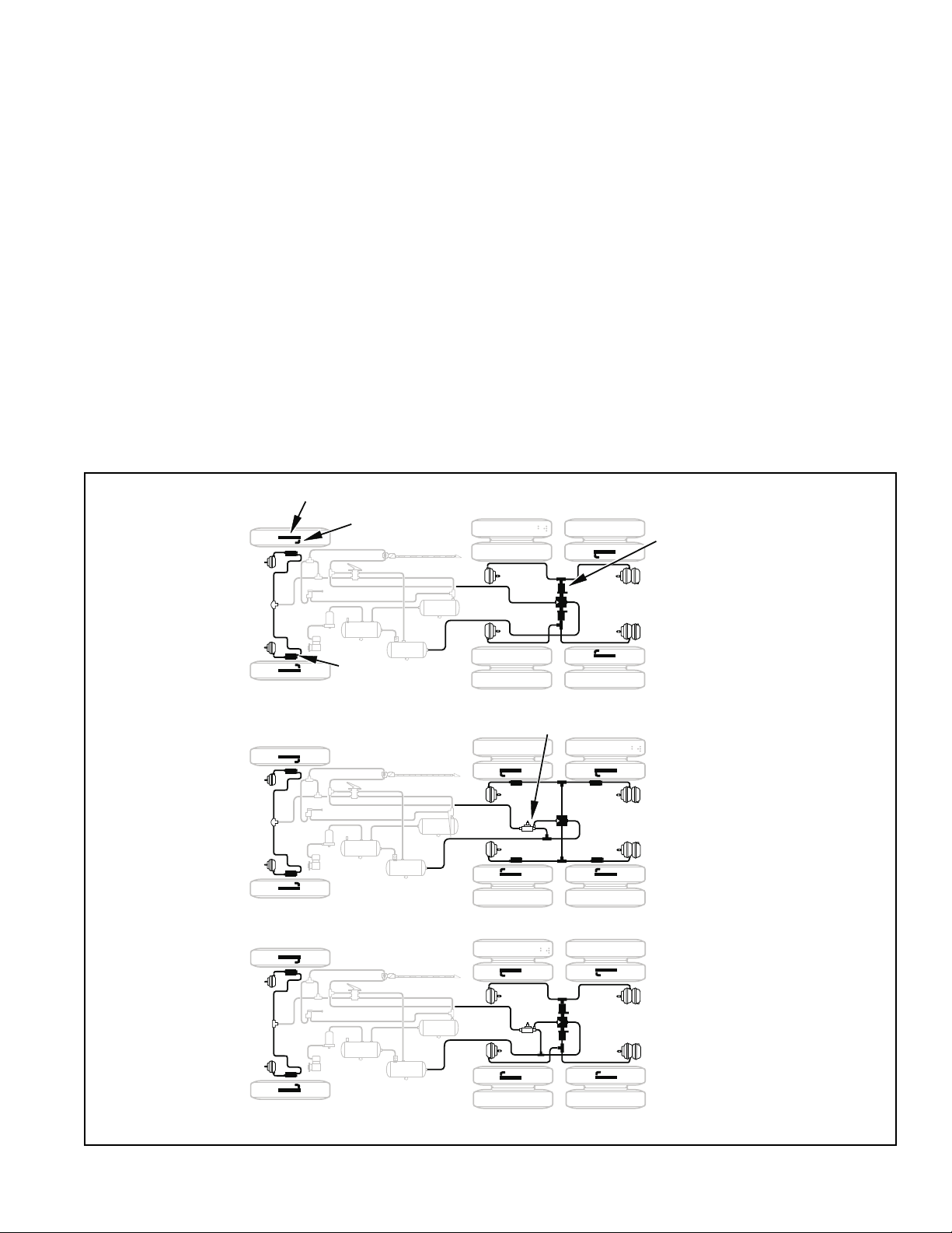
SYSTEM CONFIGURA TIONS
Available Configurations
A wide variety of system configurations are available (refer
to Figure 17). It is important to be able to read system
configurations and to be able to properly reconfigure a
system when necessary .
When to Configure
ECUs are factory configured for the most common
requirements. Basic systems are setup for 4s-4m operation
with retarder control via retarder relay. Standard systems
are setup for 6s-4m operation with retarder control via
engine data link. For applications other than these factory
configurations (for example use of a retarder control relay ,
4s-3m operation, 6s-6m operation or traction control), it is
necessary to perform a configuration or “setup” process.
This process sets up the ECU for the components that are
installed so that proper control and fault tolerance will be
Fault Codes
Tone Ring
Wheel SpeedSensor
(WSS)
implemented. The diagnostic switch, MPSI Pro-Link® tool
or ServiceRanger PC software may be used to configure
to a higher level (add components or functionality). If it is
desired to move the configuration downward (fewer
components than standard), the ProLink tool or
ServiceRanger PC software must be used.
How to Configure
Use the “SYSTEM SETUP” menu with the MPSI ProLink
tool, the diagnostic switch (refer to page 25 for procedure)
or ServiceRanger PC software. Use of the “SETUP”
function will also clear inactive trouble codes from the
system. However it is recommended that the “CLEAR
TROUBLE CODES” function be used for clearing inactive
codes.
Verification
It is important to verify that the intended configuration has
been obtained. Refer to Figure 20 (page 17) for proper
interpretation of configuration blink codes.
RearAxle
ValveAssembly
®
Pressure
Modulator
Valve
(PMV)
4S -4M
6S -6Mw/ATC
ATC
Valve
FIGURE 18 - Typical ABS Configurations
6S -4Mw/ATC
15
Page 16

Test Equipment
Bendix recommends the use of the following products to
troubleshoot the ABS system:
• A multimeter or digit al volt-ohmmeter (DVOM).
• Eaton ServiceRanger PC software or an MPSI ProLink
hand-held tester.
Multimeter
A multimeter can be used to check:
• Speed sensor circuit resistance.
• PMV and ATC valve solenoid resistances.
• ABS power circuit voltages.
• Engine data link voltages.
• Retarder control relay .
• Wiring harness diagnostic trouble codes.
ServiceRanger PC Software
ServiceRanger PC software can be used to read and clear
error codes and obtain a short description of failures. The
software can initiate test sequences for controller outputs
and can also read system data such as voltage at the
®
ECU, wheel speeds and cutout speeds.
CAUTION: Eaton ServiceRanger PC software can activate
output tests for all output devices. Since these tests can
affect operation of the vehicle braking system, the ECU
incorporates special safety protection. One axle must
show zero speed or the test will be halted.
ServiceRanger
Software CD
Laptop PC
1. Monitor Data
Wheel Speeds
Cut-Out Speeds
Input Voltages
Switch States
Deutsch HD-10
Connector
Serial Communicator
Interface
2. Retrieve TroubleCodes
Retrieve Trouble Codes
Clear Trouble Codes
To Diagnostic
Connector
PCINTERF
ACE
ServiceRanger Main MenuOptions
1. Monitor Data
2. Retrieve DiagnosticTroubleCodes
3.Advanced Product Functions
4. Product Downloads
3. Adv. Prod.Functions
TestValves
TestLights
TestRetarderControl
4. Product Downloads
Read ECU Configuration
Configure ECU
DisableATC
FIGURE 19 - ServiceRanger Menus & Hardware Setup
16
Page 17

Hand-Held Tester
An MPSI ProLink® hand-held tester with Bendix proprietary
cartridge can be used to read and clear error codes and
obtain a short description of failures. The tester can initiate
test sequences for controller outputs and can also read
system data such as voltage at the ECU, wheels speeds
and cutout speeds. A st andard heavy duty truck cartridge
may also be used, but cannot initiate test sequences.
CAUTION: The ProLink hand-held tester can activate
output tests for all output devices. Since these tests can
affect operation of the vehicle braking system, the ECU
incorporates special safety protection. One axle must show
zero speed or the test will be halted.
Release
Button
Eaton
Applications
Applications Card
Fault Codes
MPC™ Cartridge
Bendix
MPSI Pro-Link
Deutsch HD-10
Connector
®
To
Diagnostic
Connector
Diagnostic and
Power Cable
Eaton ABS
Press Enter
1. System INFO
2. Trouble codes
3. Monitor Data
4. Component Test
5. System Set-up
6. ATC Disable
7. English/Metric
8. Exit
1. System INFO
Part No.
Date
Serial No.
Software No.
System Configuration
–ABS
– ATC
Steer Wheel Size
Rear Wheel Size
Rear-Rear Wheel Size
MIC Parameter
2. Trouble Codes
Actual Trouble Codes
Extended Trouble
Codes
Clear Memory
3. Monitor Data
Wheel Speeds
Cut out Speeds
System Volts
Input Switches
FIGURE 20 - Hand-Held Tester Menus and Set-Up
4. Component Test
ValveRoutines
TCV
WL
TCL
RET
Interface
5. System Setup
System Config
6. ATC Disable
For Dyno Test
7. English/Metric
8. Exit
17
Page 18

Diagnostic Switch
.
Blink Codes – System Configuration and System Faults.
By properly actuating the ABS diagnostic button,
configuration codes and diagnostic trouble codes can be
retrieved as blinked sequences on the ABS indicator lamp.
Configuration codes are sequences of four blinked digits
while diagnostic trouble codes appear as two blinked
numbers. Refer to the charts beginning on page 19 for a
description of these codes. T o perform any of the activities
listed below, simply follow the step s as given. If you make
a mistake during one of the steps, stop and start over at the
beginning of the procedure.
All blink codes are displayed by the ABS indicator lamp
only . The ATC lamp does not display blink codes.
Note: Before attempting any repairs:
1. Retrieve the configuration codes and diagnostic trouble
codes (write them down).
2. Reconfigure the ECU if the configuration does not agree
with the installed hardware. The ECU cannot be
configured downward (components removed) with the
diagnostic button. For example, a 6S-4M cannot be
configured to 4S-4M. Downward configurations require
the use of a ProLink tool or ServiceRanger software.
3. If the configuration is correct, clear the diagnostic trouble
codes. The process for clearing the trouble codes and
reconfiguring the ECU is the same when using the
diagnostic button.
4. Once again retrieve the diagnostic trouble codes. Only
active codes will now be displayed.
Retrieving Diagnostic Trouble Codes
• Turn the ignition key to “ON.”
• If vehicle is equipped with A TC, apply and release brakes
once before proceeding.
• Press and hold the diagnostic button for two seconds
and release.
• Two-number blink codes are retrieved and displayed.
2 Sec
Reading Configuration Codes
• Turn the ignition key to “ON.”
• Press and hold the diagnostic button for two seconds
and release.
• Without pause, press the diagnostic button a 2nd time
for two seconds and release.
• Four-digit configuration code is retrieved and displayed.
2 Sec 2 Sec<1S
18
Page 19

Blink Code
Sequence
1st
VOLTAGE CONFIGURATIONS
Flashes Description
1 12 Volt System
2 24 Volt System
1.5 Sec.
Pause
2nd
4.5 Sec.
Pause
3rd
1.5 Sec.
Pause
4th
ABS CONFIGURATIONS
Flashes Description
Fault Codes
2 4 Sensors/4Modulator Valves
3 4 Sensors/3Modulator Valves
6 6 Sensors/4Modulator Valves
8 6 Sensors/6Modulator Valves
9 6 Sensors/5Modulator Valves
– SelectLow Steer
RETARDERCONFIGURATIONS/INTERAXLE
Flashes Engine Interface Retarder RelayControl Interaxle LockControl
1 (5) NO NO NO (YES)
2 (6) YES NO NO (YES)
3 (7) YESNO NO (YES)
4 (8) YES YES NO (YES)
ATCCONFIGURATIONS
Flashes Engine Control Brake Control
2 NO NO
3 N/A N/A
4 N/A N/A
5 YES YES
FIGURE 21 - Reading ABS Configuration Codes
19
Page 20

Clearing Diagnostic Trouble Codes and/or
System Configuration
• With the ignition “OFF” press and hold the diagnostic
button.
• Turn the ignition key to “ON” while pressing the
diagnostic button.
• Wait two seconds and release the diagnostic button.
• Press and release the brake pedal.
• ECU is reconfigured to match connected components
and diagnostic trouble codes are cleared.
• Repeat the “Retrieving Diagnostic Trouble Codes”
procedure to verify that the trouble codes are cleared.
2 + Sec
Disabling ATC for Dyno T es ting
• Turn the ignition key to “ON.”
• Press and hold the diagnostic button for at least 3
seconds and release.
• ATC light turns “ON” and ABS light blinks 17 • 8 indicating
A TC is disabled.
• At the next ignition cycle ATC will be reactivated.
3+ Sec
First TroubleCode
first half ofcode
1.5 second pause
second half ofcode
FIGURE 22 - Typical Blink Code Report
4.5
second
pause
Additional TroubleCodes
first half ofcode
1.5 second pause
second half ofcode
4.5 second
pause
Sequence continues
until all troublecodes
are reported.
20
Page 21

Blink Codes
1st. 2nd.
11 –/– No Trouble Found
21 001/000 Sensor air gap too large. Left Steer Sensor
22 001/008 Air gap too large or sensor shorted.
23 001/010 Speed Sensor signal is noisy.
24 001/008 Wheel locked too long during an ABS cycle.
25 001/008 High deceleration rate at wheel site or sensor shorted.
26 001/012 Sensor shorted low or high or sensor open.
27 001/012 Internal error at the sensor port of the ECU.
28 001/002 Sensor in the wrong location for the system configuration.
31 002/000 Sensor air gap too large. Right Steer Sensor
32 002/008 Air gap too large or sensor shorted.
33 002/010 Speed Sensor signal is noisy.
34 002/008 Wheel locked too long during an ABS cycle.
35 002/008 High deceleration rate at wheel site or sensor shorted.
36 002/012 Sensor shorted low or high or sensor open.
37 002/012 Internal error at the sensor port of the ECU.
38 002/002 Sensor in the wrong location for the system configuration.
41 003/000 Sensor air gap too large. Left Rear Sensor.
42 003/008 Air gap too large or sensor shorted.
43 003/010 Speed Sensor signal is noisy.
44 003/008 Wheel locked too long during an ABS cycle.
45 003/008 High deceleration rate at wheel site or sensor shorted.
46 003/012 Sensor shorted low or high or sensor open.
47 003/012 Internal error at the sensor port of the ECU.
48 003/002 Sensor in the wrong location for the system configuration.
51 004/000 Sensor air gap too large. Right Rear Sensor.
52 004/008 Air gap too large or sensor shorted.
53 004/010 Speed Sensor signal is noisy.
54 004/008 Wheel locked for too long during an ABS cycle.
55 004/008 High deceleration rate at a wheel site or sensor shorted.
56 004/012 Sensor shorted low or high or sensor open.
57 004/012 Internal error at the sensor port of the ECU.
58 004/002 Sensor in the wrong location for the system configuration.
MID 136
SID/FMI
Fault Codes
Description
Location
21
Page 22

Blink Codes
1st. 2nd.
61 005/000 Sensor air gap too large. Left Rear Sensor.
62 005/008 Air gap too large or sensor shorted.
63 005/010 Speed Sensor signal is noisy.
64 005/008 Wheel locked for too long during an ABS cycle.
65 005/008 High deceleration rate at wheel site or sensor shorted. Left Rear Sensor.
66 005/012 Sensor shorted low or high or sensor open. (continued).
67 005/012 Internal error at the sensor port of the ECU.
68 005/002 Sensor in the wrong location for the system configuration.
71 006/000 Sensor air gap too large. Right Rear Sensor.
72 006/008 Air gap too large or sensor shorted.
73 006/010 Speed Sensor signal is noisy.
74 006/008 Wheel locked too long during an ABS cycle.
75 006/008 High deceleration rate at wheel site or sensor shorted.
76 006/012 Sensor shorted low or high or sensor open.
77 006/012 Internal error at the sensor port of the ECU.
78 006/002 Sensor in the wrong location for the system configuration.
81 007/003 Short circuit from the release solenoid to voltage. Left Steer Axle PMV.
82 007/004 Short circuit from the release solenoid to ground.
83 007/005 Open circuit at the release solenoid.
84 007/005 Open circuit on the common line to the valve.
85 007/003 Short circuit from the hold solenoid to voltage.
86 007/004 Short circuit from the hold solenoid to ground.
87 007/005 Open circuit at the hold solenoid.
88 007/002 System configuration is incorrect.
8 10 151/014 Inter-axle differential control circuit shorted high. IAD Circuit.
8 10 151/014 Inter-axle differential control circuit shorted low or open.
91 008/003 Short circuit from the release solenoid to voltage. Right Steer Axle PMV.
92 008/004 Short circuit from the release solenoid to ground.
93 008/005 Open circuit at the release solenoid.
94 008/005 Open circuit on the common line to the valve.
95 008/003 Short circuit from the hold solenoid to voltage.
96 008/004 Short circuit from the hold solenoid to ground.
97 008/005 Open circuit at the hold solenoid.
98 008/002 System configuration is incorrect.
MID 136
SID/FMI
Description
Location
22
Page 23

Blink Codes
1st. 2nd.
10 1 009/003 Short circuit from the release solenoid to voltage. Left Rear Axle PMV.
10 2 009/004 Short circuit from the release solenoid to ground.
10 3 009/005 Open circuit at the release solenoid.
10 4 009/005 Open circuit on the common line to the valve.
10 5 009/003 Short circuit from the hold solenoid to voltage.
10 6 009/004 Short circuit from the hold solenoid to ground.
10 7 009/005 Open circuit at the hold solenoid. Left Rear Axle PMV (cont.).
10 8 009/002 System configuration is incorrect.
10 or 11 9 014/003 Common side of valves – stray voltage detected. PMV Commons.
10 or 11 10 014/003 Common side of valves shorted high.
10 or 11 11 014/004 Common side of the valves shorted to ground.
11 1 010/003 Short circuit from the release solenoid to voltage. Right Rear Axle PMV.
11 2 010/004 Short circuit from the release solenoid to ground.
11 3 010/005 Open circuit at the release solenoid.
11 4 010/005 Open circuit on the common line to the valve.
11 5 010/003 Short circuit from the hold solenoid to voltage.
11 6 010/004 Short circuit from the hold solenoid to ground.
11 7 010/005 Open circuit at the hold solenoid.
11 8 010/002 System configuration is incorrect.
12 1 011/003 Short circuit from the release solenoid to voltage Left Rear Axle PMV.
12 2 011/004 Short circuit from the release solenoid to ground.
12 3 011/005 Open circuit at the release solenoid.
12 4 011/005 Open circuit on the common line to the valve.
12 5 011/003 Short circuit from the hold solenoid to voltage.
12 6 011/004 Short circuit from the hold solenoid to ground.
12 7 011/005 Open circuit at the hold solenoid.
12 8 011/002 System configuration is incorrect.
13 1 012/003 Short circuit from the release solenoid to voltage. Right Rear Axle PMV.
13 2 012/004 Short circuit from the release solenoid to ground.
13 3 012/005 Open circuit at the release solenoid.
13 4 012/005 Open circuit on the common line to the valve.
13 5 012/003 Short circuit from the hold solenoid to voltage.
13 6 012/004 Short circuit from the hold solenoid to ground.
13 7 012/005 Open circuit at the hold solenoid.
13 8 012/002 System configuration is incorrect.
MID 136
SID/FMI
Fault Codes
Description
Location
23
Page 24

Blink Codes
1st. 2nd.
14 5 018/003 Solenoid in ATC valve shorted high. ATC Valve.
14 6 018/004 Solenoid in ATC valve shorted to ground.
14 7 018/005 ATC valve open circuit.
14 8 018/002 ATC valve found when it should not be present.
14 12 249/002 or 231/002 Time-out or no connection to engine link (J1922/1939). Data Link.
15 1 254/012 ECU internal trouble code. ECU.
15 2 253/012 ECU internal trouble code.
15 3 253/013 ECU internal trouble code.
15 4 253/012 ECU internal trouble code. ECU (cont.).
15 5 254/002 ECU internal trouble code.
15 6 254/002 ECU internal trouble code.
15 7 254/002 ECU internal trouble code.
15 8 253/013 ECU internal trouble code.
15 9 231/012 ECU internal trouble code.
15 10 254/012 ECU internal trouble code.
15 11 254/012 ECU internal trouble code.
16 1 or 5 251/004 Excessive voltage on PMV Power. Power Circuits.
16 2 or 6 251/003 Low voltage found on PMV Power.
16 3 or 7 251/005 No voltage found on PMV Power.
16 4 or 8 251/005 Open circuit found on PMV Ground.
16 9 251/004 Excessive voltage found on ECU Power.
16 10 251/003 Low voltage found on ECU Power.
16 11 251/002 Voltage difference between PMV Power inputs is too high.
17 1 013/003 Retarder control relay shorted high or open circuit.
17 2 013/004 Retarder control relay shorted to ground.
17 3 249/002 or 231/002 J1922/1939 date link not functioning.
17 4 249/002 or 231/002 J1922/1939 date link time out.
17 5 253/013 Tire size, front to rear out of range.
17 6 253/013 Tire size out of range or parameter fault.
17 7 — Brake light switch not pushed at this power cycle.
17 8 — ATC system is disabled for dynamometer test.
17 10 023/014 Indicator lamp circuit is faulty.
17 12 151/014 Sensor memory bit set, (A sensor trouble code has
MID 136
SID/FMI
Description
occurred, the ECU must read wheel speeds on all wheels
to clear this trouble code.)
Location
24
Page 25

Speed Sensor Troubleshooting
Follow the steps listed below to locate and correct sensor
related ABS trouble codes.
1. Access active trouble code(s) using either the Blink
Code procedure, with ServiceRanger or the Hand-held
Tester procedure.
2. Lookup the code description, the possible causes and
the repair procedures provided in this section.
3. Perform the recommended repair procedures.
4. After the repairs are completed, clear all codes and
check for any additional codes.
5. If a sensor related trouble code has occurred, a code
17•12 will remain in the system until the vehicle has
been driven.
Fault Codes
FIGURE 23 - Typical Wheel Speed Sensor Circuit
TOP- Looking intoharness connector
10
7
4
11
8
5
12
9
6
10
1
2
3
5
8
14
11
6
9
15
12
5
8
2
6
9
3
2
5
2
3
6
3
1
4
1
4
7
1
4
7
13
Harness Connector PIN Circuit Description
B (6-Way) 4 SpeedSensor (+)Left Steer
5 SpeedSensor (-)Left Steer
C (9-Way) 4 SpeedSensor (+)Right Steer
5 SpeedSensor (-)Right Steer
D (15-Way) 5 SpeedSensor (+)Left Rear
6 SpeedSensor (-)Left Rear
8 SpeedSensor (+)Right Rear
9 SpeedSensor (-)Right Rear
E (12-Way) 5 SpeedSensor (+)Left RearRear
6-channel 6 Speed Sensor (-) Left Rear Rear
Only 8 SpeedSensor (+)Right RearRear
9 SpeedSensor (-)Right RearRear
*
Not Used On BasicSystem
7
8
16
14
17
18
15
2
5
8
11
3
6
9
12
1
4
7
10
13
ABCDE
9
10
11
12
X1 Grey
7
6
8
5
9
4
10
3
11
2
12
1
X2 Black
6
7
5
8
4
9
3
10
2
11
1
12
X3 Green
7
6
8
5
4
9
3
10
2
11
1
12
6
5
4
3
2
1
X4 Brown
Harness Connector PIN Circuit Description
X2 (Black) 5 Speed Sensor(-) Right Steer
6 SpeedSensor (+)Right Steer
7 SpeedSensor (-)Left Steer
8 SpeedSensor (+)Left Steer
X3 (Green) 1 SpeedSensor (-)Left Rear
2 SpeedSensor (+)Left Rear
3 SpeedSensor (-)Right Rear
4 SpeedSensor (+)Right Rear
*
*
*
*
X4 (Brown) 3 Speed Sensor(-) Left Rear Rear
6-channel 4 Speed Sensor(+) LeftRear Rear
Only 5 SpeedSensor (-)Right RearRear
6 SpeedSensor (+)Right RearRear
*
Not Used On BasicSystem
*
*
*
*
Speed Sensor ResistanceTest
The correct resistanceforthespeed sensor circuit is between 950 ohmsand1900ohms.
Measure resistance atthewheellocation to check the speed sensor.
Measure resistance attheappropriateECU harness connector pins to check thecableandspeed sensor.
Note: Refer tothechartfor pin identification.
FIGURE 24 - Wheel Speed Sensor Harness Circuit Descriptions and Resistance Test
25
Page 26

The 17•12 Sensor Memory Diagnostic Trouble
Code
The ABS indicator lamp indication and 17•12 diagnostic
trouble code are provided to remind the service technician
of the need to verify the performance of the ABS wheel
speed sensors by driving the vehicle after servicing the
sensors. ABS wheel speed sensors do not generate signals
unless the wheels are turning. Because of this, certain
sensor codes can only be detected when the vehicle is in
motion.
The trouble code 17•12 is generated after the initial sensor
codes are cleared. The ABS indicator lamp remains lit.
The trouble codes must be rechecked after clearing the
sensor codes in order to see 17•12 reported.
A 17•12 trouble code and ABS indicator lamp signal for
sensor code cannot be cleared using a ProLink,
ServiceRanger software or the diagnostic button. They can
only be cleared by driving the vehicle. The ABS ECU will
clear the 17•12 blink code and turn off the ABS indicator
lamp when all active sensor code issues are resolved and
the vehicle is driven above 5 mph. The ABS ECU must
detect speeds at all monitored wheels for the condition to
clear.
Procedure:
1. Check trouble codes.
2. Troubleshoot and eliminate causes for all trouble codes.
3. Clear trouble codes.
4. Check trouble codes again (17•12 will be reported if
sensor codes are cleared).
5. If 17•12 error code is reported, drive vehicle above 5
mph (ABS indicator lamp will go out and 17•12 trouble
code will be cleared after a short period if all sensor
signals are acceptable).
Note: If sensor codes still exist, the ABS indicator lamp
will remain lit. The trouble codes will be logged once again
after driving the vehicle. If more than one sensor site is
affected, the codes may not be re-logged by the ECU until
the vehicle has been driven and held above 20 mph for 35 minutes.
For more detailed troubleshooting, monitor the wheel
speeds and cut-out speeds with ServiceRanger or a ProLink
hand-held diagnostic tool. Troubleshoot and repair any
speed sensor not reporting a wheel speed or showing a
high cut-out speed.
Cut-out speeds are an indication of the strength of the
sensor signal to the ECU and are proportional to air gap.
Cut-out speeds should be in the range of 3-8 mph. Lower
numbers indicate a stronger and better signal than higher
numbers. High values indicate a sensor with an unreliable
or non-existent signal.
26
Page 27

Blink Code
Sequence
Flashes Location
1st
1.5 Sec.
Pause
2nd
2 LeftSteer
3 RightSteer
4 LeftRear
5 RightRear
6 LeftRear Rear
7 RightRear Rear
Fault Codes
Flashes Condition
1 Sensorair gap toolarge.
2 Airgap too largeor sensor
3 Speedsensor signal isnoisy.
3
2
2
shorted.
3
5
4
Action
If necessary, clean andlubricatesensor. Press intomountinghole until itbottoms against
tone wheel. Cleartrouble code andverifythat code iscorrected by testdriving the vehicle.
The indicator lampwill remain onuntilproper sensor outputis detected eventhough the code
has been cleared.
Check sensor resistance.If sensor resistanceisout of range,replace sensor. Clean and
lubricate sensor. Press intomounting hole untilitbottoms against tonewheel. Clear trouble
code and verifythat code iscorrectedby test drivingthe vehicle.The indicatorlamp will remain
on until propersensor output isdetectedeven though thecode has beencleared. Use
approved lubricant.
Examine tone ringfor damage. Replacetonering and/or hubif necessary. Check wheel
bearing adjustment. Adjust wheelbearings if necessary. Cleartrouble code andverifythat code
is corrected bytest driving thevehicle.The indicator lampwill remain onuntil proper sensor
output is detectedeven though thecodehas been cleared.
7
6
4 Wheellocked for excessive
period of timeduring an ABS cycle.
5 Excessiverate of deceleration
found at awheel site.
6 Sensorconnection shorted lowor
high or sensoris open.
7 Thereis an internalerror at the
sensor port ofthe ECU.
8 Asensorhas been foundin the
wrong location.
Check mechanical functionof brake. Checkforkinked or restrictedhoses. Clear troublecode
and verify thatcode is correctedbytest driving thevehicle.The indicator lampwill remain on
until proper sensoroutput is detectedeventhough the codehas been cleared.
Check for damagedtone ring orexcessiverun out. Repairtone ring and/oradjust wheel
bearings. Clear troublecode and testdrivethe vehicle. The indicator lampwill remain onuntil
proper sensor outputis detected eventhoughthe trouble codehas been cleared.
Use an ohmmeter to verifypropersensor resistance (Fig24). Check harnessfor shorts or
opens. Repair harnessand/or replace sensorasnecessary.Clear trouble codeand verify that
code is correctedby test drivingthevehicle.
sensor output isdetected even thoughthetrouble code hasbeen cleared.
Clear trouble codeand test drivethevehicle. Theindicator lamp willremain on untilproper
sensor output isdetected even thoughthecode has beencleared. If troublecode recurs, or
cannot be cleared,replace ECU.
Check the controlunit configuration andverifythat sensors arewired in theproper location
for the configuration(Refer to Schematic).
FIGURE 25 - Speed Sensor Diagnostic Trouble Code Troubleshooting Guide
The indicator lampwill remain onuntilproper
27
Page 28

Wheel End Speed Sensor Repair
Front Axle Speed Sensor
The front axle speed sensor is located on the inboard side
of the steering knuckle.
CAUTION: Block wheels before beginning this procedure.
Follow all standard safety procedures, outlined by , but not
limited to, the General Precautions listed on page 13 of
this document.
CAUTION: Do not work under a vehicle supported by a
jack.
Removal
1. Disconnect sensor cable from harness.
2. Remove the sensor from the sensor bushing. (Do not
pull on cable.)
3. Remove the speed sensor friction sleeve from the steer
knuckle.
Sensor
Friction Sleeve
ABS
Sensor
Bushing
Installation
1. Install the sensor bushing with the flange stops towards
the inboard side of the vehicle.
2. Apply high-temperature silicon-base d grease to the
body of the speed sensor .
3. Push the speed sensor completely into sensor bushing
by hand until it stops against the tone ring. The speed
sensor is properly installed and adjusted when it is
touching the tone ring.
NOTE: The speed sensor must slide freely in and out of
the mounting sleeve bore. Operating the vehicle with
seized components will damage the speed sensor and
the tone ring.
4. T est the installation.
5. Check the cable routing and connections.
6. Clear the trouble codes. A 17•12 trouble code will
remain in the system until the vehicle has been driven.
7. T est drive the vehicle and verify that the ABS warning
lamp operates properly .
FIGURE 26 - Front Speed Sensor Components
Push
Sensor
FIGURE 27 - Wheel Speed Sensor Installation
28
Page 29

Rear Axle Speed Sensor
The rear axle speed sensor located inside the brake drum
and is only accessible by removing the wheel and drum
assembly.
NOTE: For diagnostic and service information on in-axle
speed sensors, please contact Dana Corporation.
CAUTION: Block wheels before beginning this procedure.
Follow all standard safety procedures, outlined by , but not
limited to, the General Precautions listed on page 13 of
this document.
CAUTION: Do not work under a vehicle supported by a
jack.
Removal
1. Back off the slack adjuster to release the brake shoes.
2. Remove the wheel and tire assembly from the axle.
3. Remove the brake drum.
4. Remove the speed sensor with bushing from the
mounting block on the axle housing. Use twisting motion
and avoid pulling on the cable.
5. Disconnect any fasteners that hold sensor cable to other
components and disconnect the speed sensor from the
harness.
Fault Codes
Sensor
Friction Sleeve
Sensor Block
Installation
1. Install the sensor bushing with the flange stops toward
the inboard side of the vehicle.
2. Apply a non-conductive grease lubricant to the body of
the speed sensor.
3. Push the speed sensor completely into sensor bushing
by hand until it stops against the tone ring. The speed
sensor is properly installed and adjusted when it is
touching the tone ring.
NOTE: The speed sensor must slide freely in and out of
the mounting sleeve bore. Operating the vehicle with seized
components will damage the speed sensor and the tone
ring.
4. Route the cable to the frame.
5. Connect sensor cable to harness and install fasteners
to hold the sensor cable in position.
6. Install the brake drum on the wheel hub.
7. Adjust the rear axle brakes.
8. Install the wheel and tire assembly and tighten the wheel
nuts.
9. Test the inst allation.
10.Check the cable connections.
11. Clear the trouble codes. A 17•12 trouble code will remain
in the system until the vehicle has been driven.
12.Test drive the vehicle and verify that the ABS indicator
lamp operates properly .
FIGURE 28 - Rear Speed Sensor Components
29
Page 30

Pressure Modulator Valve (PMV)
Troubleshooting
Follow the steps listed below to locate and correct ABS
modulator valve problems.
1. Access active trouble code(s) using either the Blink
Code procedure or the hand-held tester procedure.
2. Lookup the code description, the possible causes and
the repair procedures provided in this section.
3. Perform the recommended repair procedures.
4. After the repairs are completed, clear all codes and
check for any additional codes.
ECU
FIGURE 29 - Typical PMV Circuit
Relay
Valve
No
Connection
Common
Release
1
32
Hold
Twist-LockConnector
Twist-Lock
Connector
Common
PMV Resistance Test
Measure resistance at the PMV location
to check the valve.
1
2
3
Hold
Threaded
Connector
FIGURE 30 - PMV Harness Circuit Descriptions and Resistance Test
Looking IntoValve
Threaded Connector
Release
Measure resistance at the appropriate
ECU harness connector pins to check
the cable and valve.
Note: Refer to the chart for pin
identification.
Measure Measure Resistance
From: To: Range:
Common Hold 3-8 Ohms
Common Release 3-8 Ohms
HoldRelease 6-16 Ohms
30
Page 31

Cab Mount Frame Mount
TOP– Looking into harnessconnector
10
13
7
4
1
7
4
1
4
10
7
4
1
11
14
8
5
2
8
11
8
5
2
12
15
9
12
9
6
3
6
5
3
9
6
Harness Connector PIN Circuit Description
B (6-Way) 1 PMV 1(Release) Left Steer
2 PMV1 (Hold)Left Steer
3 PMV1 CommonLeft Steer
C (9-Way) 7 PMV 2 (Release)Right Steer
8 PMV2 (Hold)Right Steer
Fault Codes
9 PMV2 CommonRight Steer
D (15-Way) 1 PMV3 (Release) Left Rear
2 PMV3 (Hold)Left Rear
3 PMV3 CommonLeft Rear
D (15-Way) 10 PMV4 (Release)Right Rear
11 PMV4 (Hold)Right Rear
12 PMV 4 CommonRight Rear
E (12-Way) 1 PMV5 (Release)Left RearRear
6-channel 2 PMV5 (Hold)Left Rear Rear
Only 3 PMV 5 Common LeftRear Rear
E (12-Way) 10 PMV 6(Release) Right RearRear
6-channel 11 PMV 6(Hold) RightRear Rear
Only 12 PMV 6Common RightRear Rear
1
2
5
2
3
6
3
7
8
13
16
10
7
4
14
17
11
8
18
5
12
9
6
15
ABCDE
9
1
10
2
11
12
3
X1 Grey
7
6
8
5
9
4
10
3
11
2
12
1
X2 Black
6
7
5
8
4
9
3
10
2
11
1
12
X3 Green
6
7
5
8
4
9
3
10
2
11
1
12
6
5
4
3
2
1
X4 Brown
Harness Connector PIN Circuit Description
X2 (Black) 2 PMV1 (Hold) Left Steer
10 PMV 1 (Release)Left Steer
11 PMV1 CommonLeft Steer
X2 (Black) 3 PMV2 (Release) Right Steer
4 PMV2 (Hold)Right Steer
9 PMV2 CommonRight Steer
X3 (Green) 10 PMV 3 (Release)Left Rear
12 PMV 3 (Hold)Left Rear
11 PMV3 CommonLeft Rear
X3 (Green) 7 PMV 4 (Release)Right Rear
9 PMV4 (Hold)Right Rear
8 PMV4 CommonRight Rear
*
*
*
*
*
*
X4 (Brown) 10 PMV 5(Release) LeftRear Rear
6-channel 12 PMV 5 (Hold)Left RearRear
Only 11 PMV5 CommonLeft RearRear
X4 (Brown) 7 PMV 6(Release) Right Rear Rear
6-channel 9 PMV 6(Hold) Right Rear Rear
Only 8 PMV 6Common RightRear Rear
*
*
*
*
*
*
*
*
Not Used OnBasic System
Not Used OnBasic System
FIGURE 31 - PMV Harness Circuit Descriptions and Resistance Test
31
Page 32

Blink Code
Sequence
1st
1.5 Sec.
Pause
2nd
Flashes Location
8 PMV 1 Left Steer
9 PMV 2 Right Steer
10 PMV 3 Left Rear
Flashes Condition
1 There is ashort between the
2 The is ashortbetween the release
3 There is anopencircuit at the
4 There is anopencircuit in the
5 There is ashortbetween the hold
6 The is ashortbetween the hold
7 There is anopencircuit at thehold
8 Avalve has beenfoundwired in the
release solenoid and supplyvoltage.
solenoid and ground.
release solenoid.
common line to thevalve.
solenoid and supply voltage.
solenoid and ground.
solenoid.
wrong location.
Flashes Location
11 PMV4 RightRear
12 PMV5 LeftRear Rear
13 PMV6 RightRear Rear
Action
Use multimeter to checkthat valve resistancesarecorrect.
If valve is OKcheck harness forshortin wiring.
Use multimeter to checkthat valve resistancesarecorrect.
If valve is OKcheck harness forshortin wiring.
Use multimeter to checkthat valve resistancesarecorrect.
If valve is OKcheck harness foropenin wiring.
Use multimeter to checkthat valve resistancesarecorrect.
If valve is OKcheck harness foropenin wiring.
Use multimeter to checkthat valve resistancesarecorrect.
If valve is OKcheck harness forshortin wiring.
Use multimeter to checkthat valve resistancesarecorrect.
If valve is OKcheck harness forshortin wiring.
Use multimeter to checkthat valve resistancesarecorrect.
If valve is OKcheck harness foropenin wiring.
Check the control unitconfiguration and verifythatvalves are wiredin the proper
location for the configuration(Refer to Schematic).
Location
PMV Commons
Flashes
Condition
9
10
11
Stray voltage has beenfound on the
common line of oneor more
of the valves
Ashort to supplyvoltagehas been
found on the commonline of oneor
more of the valves
Ashort to ground hasbeen found on
the common line ofone or moreof
the valves
1st
1.5 Sec.
Pause
Flashes
10 or 11
2nd
FIGURE 32 - PMV Diagnostic Trouble Code Troubleshooting Guide
Action
Unplug ECU and checkfor voltage onthePMV common pins.If voltage is found,
repair harness. If noproblem is foundinharness, replace ECU.Note: Before
replacing ECU clear troublecodes and verifythattrouble code isstill present
(Refer to Schematic).
Unplug ECU and checkfor short to12volts on PMV commonpins. If any are
shorted to supply, repair harness.If no short isfound in harness,replaceECU.
Note: Before replacing ECU,clear trouble codesandverify that troublecode is
still present (Refer toSchematic).
Unplug ECU and checkfor short togroundon PMV commonpins. If any are
shorted to ground, repairharness. If noshortis found inharness, replace ECU.
Note: Before replacing ECU,clear trouble codesandverify that troublecode is
still present (Refer toSchematic).
32
Page 33

ABS Modulator Valve
Removal
1. Turn ignition switch to the OFF position, and apply
parking brake.
CAUTION: Block wheels before beginning this procedure.
Follow all standard safety procedures, outlined by , but not
limited to, the General Precautions listed on page 13 of
this document.
2. Disconnect the wiring connector from the ABS valve.
3. Disconnect the air lines from the supply and delivery
ports of the ABS valve.
4. Disconnect the valve mounting fasteners.
5. Remove the ABS valve.
NOTE: To service either modular valve or the relay valve,
remove the entire assembly and then replace the individual
components (valve).
Fault Codes
Installation
1. Install the valve. Torque fasteners to manufacturers
specification.
2. Connect air lines.
• Supply to port 1 on valve.
• Service brake chamber to delivery port 2.
3. Connect the wiring connector to the ABS valve.
4. T est the inst allation:
• Modulator Valve Leak Test—Make and hold brake
application. No audible air leaks are permitted.
• Modulator Valve Component Test with Hand-Held
Diagnostic Tool—Select valve routines. Verify
proper valve location and operation with tool. Drive
the vehicle and verify ABS indicator lamp operates
properly.
5. Make several brake applications and check for prompt
brake chamber applications and release at all wheels.
Check the cable connections.
6. Clear codes.
7. Drive the vehicle and verify that the ABS indicator lamp
operates properly .
Standard RearAxle
ValveAssembly
FIGURE 33 - Rear Axle Valve Assemblies – Standard and ATC Version Shown
ATCRearAxle
ValveAssembly
33
Page 34

Performance Test of the Relay Valve
CAUTION: Block wheels before beginning this procedure.
Follow all standard safety procedures, outlined by , but not
limited to, the General Precautions listed on page 13 of
this document.
1. Park vehicle on level surface and block wheels.
2. Release parking brake and fully charge the air system
(governor cut out point).
3. Turn the engine OFF. Apply the service brake several
times, then hold and check for prompt brake air chamber
application and release at all wheels.
4. Apply brake, then hold. Coat outside of relay valve
(where cover joins body) and connection between
modulator valve and relay valve with a soap solution.
No leakage is permitted.
5. If a sluggish response is noted at all wheels, inspect for
kinked or obstructed air line leading to or from valve.
6. Increase system air pressure to governor cutoff. With
the brakes released, coat exhaust port of relay valve
with a soap solution. Leakage of a 1" bubble in 5
seconds is permissible.
7. Depress foot valve and keep depressed. Coat exhaust
port with a soap solution. Leakage of a 1" bubble in 3
seconds is permissible.
Automatic T raction Control (ATC) V alve
Troubleshooting
The following A TC troubleshooting pages provide the basic
information necessary to: identify the diagnostic trouble
code; locate the problem; review the possible cause(s);
select the correct solution and utilize proper repair
procedures.
Follow the steps listed below to locate and correct ATC
problems.
1. Access active diagnostic trouble code(s) using either
the Blink Code procedure or the hand-held tester
procedure.
2. Lookup the code description, the possible causes and
the repair procedures provided in this section.
3. Perform the recommended repair procedures.
4. After the repairs are completed, clear all codes and
check for any additional codes.
Whether the ATC Valve is used as a stand-alone valve as
shown in Figure 34 or is integrated into the cover of a relay
valve as shown in Figure 33, the troubleshooting procedure
is the same.
(1) TankAir
(2) Relayvalve
control line
34
(3) Treadle
FIGURE 34 - ATC Valve
Page 35

Cab Mount Frame Mount
TOP– Looking into harnessconnector
7
1
4
7
1
4
7
13
10
7
4
11
8
5
12
9
6
10
1
2
3
5
8
14
11
6
9
15
12
4
7
2
5
8
3
6
9
1
4
1
2
5
2
3
6
3
10
16
13
8
11
17
14
18
15
2
5
9
12
3
6
8
9
10
11
12
7
6
8
5
9
4
10
3
11
2
12
1
6
7
5
8
4
9
3
10
2
11
1
12
6
7
5
8
4
9
3
10
2
11
1
12
6
5
4
3
2
1
ABCDE
Harness Connector PIN Circuit Description
A(18-Way) 6 ATCMud and SnowSwitch
16 ATCL(ATCLight)
X1 Grey
Harness Connector PIN Circuit Description
X1 (Grey) 3 ATCL(ATC Light/ATCSwitch)
X3 (Green) 5 ATCValve–
X2 Black
D (15-Way) 4 ATC Valve +
7 ATC Valve–
Fault Codes
ATCValveResistanceTest
The correctresistancefor theATC Valvecircuit is between 9ohms and 15 ohms.
Measure resistance at theATCValve tocheckthe valve.
Measure resistanceatthe appropriate ECU harnessconnectorpins to check thecable and valve.
Note: Refertothe chart for pinidentification.
FIGURE 35 - ATC Harness Circuit Descriptions and Resistance Test
Blink Code
Sequence
Flashes
14
Location
ATCValve
6 ATC valve+
X3 Green
X4 Brown
1st
Flashes
1.5 Second
Pause
5
6
2nd
7
8
FIGURE 36 - ATC Diagnostic Trouble Code Troubleshooting Guide
Condition
Solenoid in ATC valve shorted high.
Solenoid in ATC valve shorted to
ground.
ATCvalve open circuit.
ATCvalve found when itshouldnot
be present.
Response
Use multimeter to checkthat valve resistances arecorrect (fig 34).
If valve is OKcheck harness for openin wiring.
Use multimeter to checkthat valve resistances arecorrect (fig 34).
If valve is OKcheck harness for openin wiring.
Use multimeter to checkthat valve resistances arecorrect (fig 34).
If valve is OKcheck harness for openin wiring.
Verifyproper system configuration andcomponents. Clear faults.
If error cannot becleared or recurs, replaceECU.
35
Page 36

A TC Valve Removal
CAUTION: Block wheels before beginning this procedure.
Follow all standard safety procedures, outlined by , but not
limited to, the General Precautions listed on page 13 of
this document.
1. Disconnect the wiring connector from the ATC valve.
2. Disconnect the air lines from the supply (port 1) and
delivery port (port 2) and treadle (port 3) of the ATC
valve.
3. Disconnect the valve mounting fasteners, and remove
the valve.
Installation
1. Install the A TC valve. T orque fasteners to manufacturers
specification.
2. Connect Air lines supply (port 1) delivery port (port 2)
and treadle (port 3) of the ATC valve.
Blink Code
Sequence
3. Install the wiring connector to the ATC valve.
4. T est the inst allation.
• Traction Control Valve – Leak Test:
Make and hold brake application. No audible air leaks are
permitted.
• Traction Control Valve Component Test with HandHeld Diagnostic Tool:
Select Traction Control Valve
Verify T raction control light operation
Drive the vehicle and verify ABS indicator lamp operates
properly.
CAUTION: Do not start and engage the transmission with
one wheel raised from the floor. With A TC, power will go to
the wheel on the floor and cause the vehicle to move. See
page 20 to disable ATC for dyno testing.
1st
1.5 Sec.
Pause
2nd
1st
1.5 Sec.
Pause
Flashes
14
Flashes
15
Location
ECU, Engine Interface
Flashes
12
Location
ECU
Flashes
No connection found toengine data
link (J1922/J1939).
Condition
Condition
Action
Refer to electrical schematic.Check for properconnectionof data linktoECU.
Verifythat polarity iscorrect.
Unplug connector at ECU.There should be avoltage between 0and2.5 volts on
J1922/J1939 (–) and avoltage between 2.5and5 volts onJ1922/J1939(+).
If vehicle is notequipped with J1922/J1939enginelink, use diagnostictoolto
reconfigure ECU.
Action
2nd
1–11
ECU Internal Fault
If fault cannot becleared, replace ECU.
FIGURE 37 - System and ECU Diagnostic Trouble Codes Troubleshooting Guide
36
Page 37

Blink Code
Sequence
Flashes
Location
1st
1.5 Sec.
Pause
2nd
16
Fault Codes
Power Circuits
Flashes
1or5
2or6
3or7
4or8
9
10
Condition
Excessive voltage on PMVPower
Low voltage on PMVPower
No voltage found onPMV Power
Open circuit on PMVGround
Excessive voltage found on
ECU Power
Low voltage found onECU Power
Action
Verifythat vehicle system voltageis OK (i.e.9to 16 volts).Ifvoltage is outof
range, correct system problem.Unplug connector at ECUand turn onignition
switch. If the voltageon PMV Power isdifferent than system voltage,repair
wiring. Clear trouble codesand verify that theindicator lamp turnsoutafter bulb
check.
Unplug connector at ECUand check for continuityto ground onPMVGround. If
continuity to ground isnot present, repair harness.
Verifythat vehicle system voltageis OK (i.e.9to 16 volts).Ifvoltage is outof
range, correct system problem.Unplug connector at ECUand turn onignition
switch. If the voltageon pin A-8 isdifferentthan system voltage,repairwiring.
Clear trouble codes andverify that the indicatorlamp turns outafterbulb check.
Verifythat vehicle system voltageis OK (i.e.9to 16 volts).Ifvoltage is outof
range, correct system problem.Unplug connector at ECUand turn onignition
switch. If the voltageon PMV Power isdifferent than system voltage,repair
wiring. Clear trouble codesand verify that theindicator lamp turnsoutafter bulb
check.
11
Voltagedifference between PMV
Power inputs is toohigh
Verifythat vehicle system voltageis OK (i.e.9to 18 volts).Ifvoltage is outof
range, correct system problem.Unplug connector at ECUand turn onignition
switch. If the voltageon one PMV Powerpin differs from theother by greater than
0.5 volts, repair wiring.(Check circuit breakers and/orfuses on diagonalsupply
line.) Clear trouble codesand verify that theindicator lamp turnsoutafter bulb
check.
FIGURE 38 - Power Circuit Diagnostic Trouble Codes Troubleshooting Guide
37
Page 38

Blink Code
Sequence
1st
1.5 Sec.
Pause
2nd
Flashes
17
Location
Miscellaneous
Flashes
1
2
3
4
5
6
7
8
10
12
Condition
Retarder control relay shortedhigh or
open circuit.
Retarder control relay shortedlow.
or open circuit
J1922/1939 data link notfunctioning.
(Retarder)
J1922/1939 data link timeout.
Tiresize, front torearout of range.
Tiresize out ofrangeor parameter
fault.
Brake light switch notpushed at this
power cycle.
ATCsystemis disabled for
dynamometer test.
Warninglight short, loworopen
Sensor memory bit isset
Action
Use multimeter to verifyproper voltage at theretarder control relay.
Use multimeter to verifyproper voltage at theretarder control relay.
Unplug connector at ECU.Thereshould be avoltagebetween 0 and 2.5 voltson
J1939/J1922 (–) and avoltage between 2.5 and5.0 volts on J1939/J1922(+).
Refer to schematic andcorrect wiring harness asrequired.
Unplug connector at ECU.Thereshould be avoltagebetween 0 and 2.5 voltson
J1939/J1922 (–) and avoltage between 2.5 and5.0 volts on J1939/J1922(+).
Refer to schematic andcorrect wiring harness asrequired.
There is too greata difference in therollingradius of thefrontand rear tires.
Steer axle tire radiuscannot be more than20% above rears or10%below.If the
static loaded radius ofthe rear tires isoutside the range 15.9to21.5 inches the
ECU must be recalibratedusing a diagnostic tool.
There is too greata difference in therollingradius of thefrontand rear tires.
Steer axle tire radiuscannot be more than20% above rears or10%below.If the
static loaded radius ofthe rear tires isoutside the range 15.9to21.5 inches the
ECU must be recalibratedusing a diagnostic tool.
Press brake pedal. Iferror does not clear, checkfor missing connection atbrake
light switch. If thebrake is not appliedyou should measure theresistanceof the
brake light bulb (bulbbroken?). If the brakeis applied, you shouldmeasure
vehicle system voltage. (i.e.9…16v)
Cycle ignition switch andATC willbe re-enabled.
Diagnostic switch may havebeen pressed for anexcessive period of time(>30
seconds). If not checkwiring associated with indicatorlamp.
This trouble code shouldclear when the vehicleis driven and theECUis able
to read sensor outputvoltage. If this doesnothappen, verify thatthesensors are
properly adjusted (pressed fullin to tone wheels.)
Note: Forcodes 17•3and 17•4 theproblem maybe
within theengine controller,another controlleron the
data linkor withinthe wiring orconnectors.
FIGURE 39 - Miscellaneous Diagnostic Trouble Codes Troubleshooting Guide
38
Page 39

Cab Mount ECU Pin Identification
This section shows how to identify Cab Mount ECU harness
connectors and pin locations. The charts provide a brief
description of the signal carried by each pin.
Looking IntoHarness Connector
Top
CDE
B
Fault Codes
Top
CDE
B
A
A
Top
CDE
B
A
Top
CDE
B
A
13
16
17
18
10
11
14
15
12
4
5
6
7
8
9
10
13
14
11
15
12
4
7
8
9
1
2
3
4
5
6
7
8
9
1
2
5
6
3
ConnectorA
18 -Way
Connector B
6 -Way
1
2
3
1
4
5
2
3
6
Connector C
9 -Way
Connector D
15 -Way
Top
CDE
FIGURE 40 - Cab Mount ECU – Connector Layout
1
4
7
10
8
B
A
11
9
12
2
5
3
6
Connector E
12 -Way
39
Page 40

ECU
CONNECTOR PIN DESCRIPTION
ECU
CONNECTOR PIN DESCRIPTION
A (18-Way) 1 J1922/J1939 -
™
2 Gen 4
ABS J1939 Shld/Gen 5™ ABS TIL
3 J1922/J1939 +
4 NC
5 Off Road ABS Switch (ORS)
6 ATC Mud & Snow Switch
7 Ignition, Switched
8 V Bat 2
9 V Bat 1
10 Ground - ECU
11 Ground - Diagonal 2
12 Ground - Diagonal 1
13 SAE J158714 SAE J1587+
15 NC, Interlock
16 ATC Light
17 Retarder Relay
18 Indicator Lamp/Diagnostic Switch
B (6-Way) 1 PMV1 (Left Steer), Rel Solenoid
2 PMV1 (Left Steer), Hold Solenoid
3 PMV1 (Left Steer), Common
4 Speed Sensor 2 (Left Steer) +
5 Speed Sensor 2 (Left Steer) 6 Brake Light Switch
C (9-Way) 1 NC
2 NC
3 NC
4 Speed Sensor 3 (Right Steer) +
5 Speed Sensor 3 (Right Steer) 6 NC
7 PMV2 (Right Steer), Rel Solenoid
8 PMV2 (Right Steer), Hold Solenoid
9 PMV2 (Right Steer), Common
D (15-Way) 1 PMV3 (Left Rear), Rel Solenoid
2 PMV3 (Left Rear), Hold Solenoid
3 PMV3 (Left Rear), Common
4 ATC Valve 5 Speed Sensor 4 (Left Rear) +
6 Speed Sensor 4 (Left Rear) 7 ATC Valve +
8 Speed Sensor 5 (Right Rear) +
9 Speed Sensor 5 (Right Rear) -
10 PMV4 (Right Rear), Rel Solenoid
11 PMV4 (Right Rear), Hold Solenoid
12 PMV4 (Right Rear), Common
13 NC
14 NC
15 NC
E (12-Way) 1 PMV5 (Left Rear Rear), Rel Solenoid
2 PMV5 (Left Rear Rear), Hold Solenoid
3 PMV5 (Left Rear Rear), Common
4 NC
5 Speed Sensor 6 (Left Rear Rear) +
6 Speed Sensor 6 (Left Rear Rear) 7 NC
8 Speed Sensor 7 (Right Rear Rear) +
9 Speed Sensor 7 (Right Rear Rear) -
10 PMV6 (Right Rear Rear), Rel Solenoid
11 PMV6 (Right Rear Rear), Hold Solenoid
12 PMV6 (Right Rear Rear), Common
FIGURE 41 - Cab Mount ECU – Pin Identification Chart
40
Page 41

Fault Codes
FIGURE 42 - Gen 4™ and Gen 5™ Basic Cab Mount ABS Electrical Schematic
41
Page 42

FIGURE 43 - Gen 4™ and Gen 5™ Standard Cab Mount ABS Electrical Schematic
42
Page 43

Frame Mount ECU Pin Identification
This section shows how to identify Frame Mount ECU
harness connectors and pin locations. The charts provide
a brief description of the signal carried by each pin.
10
11
12
7
8
7
8
9
6
5
4
3
2
1
9
10
11
12
6
5
4
3
2
1
X2 Black
Fault Codes
10
11
12
X3 GreenX3 Green
7
8
9
6
5
4
3
2
1
10
11
12
7
8
9
6
5
4
3
2
1
X4 Brown
FIGURE 44 - Cab Mount ECU – Pin Identification Chart
X1 Grey
43
Page 44

X1 Grey
Pin Signal Description
X1-1 IGN
X1-2 IGN
1
2
Ignition-1
Ignition-2
X1-3 ATCL ATC Light/ATC Switch
X1-4 1587
J1587+
+
X1-5 RET Retarder Control
X1-6 ENG
X1-7 ENG
X1-8 SHLD/TIL Gen 4
X1-9 1587
J1922/1939 Engine Control Link-
–
J1922/1939 Engine Control link+
+
™
ABS J1939 Shield/Gen 5™ ABS TIL
J1587-
–
X1-10 WL ABS WL/Diagnostic Switch
X1-11 GND
X1-12 GND
Ground
2
Ground
1
X2 Black X4 Brown
X3 Green
Pin Signal Description
X3-1 SS
X3-2 SS
X3-3 SS
X3-4 SS
LR
LR
RR
RR
X3-5 ATCV
X3-6 ATCV
X3-7 REL
X3-8 CMN
X3-9 HLD
X3-10 REL
X3-11 CMN
X3-12 HLD
-
+
RR
RR
RR
LR
LR
LR
Speed Sensor, Left RearSpeed Sensor, Left Rear+
Speed Sensor, Right RearSpeed Sensor, Right Rear+
Traction Control V alveTraction Control Valve+
Release Sol, Right Rear
Common, Right Rear
Hold Sol, Right Rear
Release Sol, Left Rear
Common, Left Rear
Hold Sol, Left Rear
Pin Signal Description
X2-1 BLS Brake Light Switch
X2-2 HLD
X2-3 REL
X2-4 HLD
X2-5 SS
X2-6 SS
X2-7 SS
X2-8 SS
X2-9 CMN
X2-10 REL
X2-11 CMN
LS
RS
RS
RS
BS
LS
LS
RS
LS
LS
Hold Sol, Left Steer
Release Sol, Right Steer
Hold Sol, Right Steer
Speed Sensor, Right SteerSpeed Sensor, Right Steer+
Speed Sensor, Left SteerSpeed Sensor, Left Steer+
Common, Right Steer Valve
Release, Left Steer Valve
Common, Left Steer Valve
X2-12 ORS Off Road Switch
FIGURE 45 - Frame Mount ECU – Pin Identification Chart
Pin Signal Description
X4-1 DLC
X4-2 DLC
X4-3 SS
X4-4 SS
X4-5 SS
X4-6 SS
X4-7 REL
X4-8 CMN
X4-9 HLD
X4-10 REL
X4-11 CMN
X4-12 HLD
-
+
LRR
LRR
RRR
RRR
RRR
C+
RRR
LRR
LRR
LRR
Diff Lock ControlDiff Lock Control+
Speed Sensor Left Rear RearSpeed Sensor Left Rear Rear+
Speed Sensor Right Rear RearSpeed Sensor Right Rear Rear+
Release Sol, Right Rear Rear
Common, Right Rear Rear
Hold Sol, Right Rear Rear
Release Sol, Left Rear Rear
Common, Left Rear Rear
Hold Sol, Left Rear Rear
44
Page 45

Fault Codes
FIGURE 46 - Gen 5™ Basic Frame Mount ABS Electrical Schematic
45
Page 46

FIGURE 47 - Gen 4™ and Gen 5™ Standard Frame Mount ABS Electrical Schematic
46
Frame Mount
Page 47

Glossary
ABS — Antilock Brake System.
ABS Event — Impending wheel lock situation that causes the
ABS controller to activate the modulator valve(s).
Air Gap — Distance between the Sensor and tone ring.
Anti-Compounding Valve — Prevents the application of the
service and spring brakes at the same time. Depending on
vehicle design, the anti-compounding valve may be installed in
combination with a relay valve or quick release valve.
Apply Timing — The time from the movement of the service
brake control for each brake chamber to reach 60 psi, with an
initial service reservoir pressure of 100 PSI.
ASR — Automatic Slip Regulation. Another name for traction
control.
ATC — Automatic Traction Control. An additional ABS function
in which engine torque is controlled and brakes are applied
differentially to enhance vehicle traction.
ATC Light — A light that indicates when traction control is
operating.
Channel — A controlled wheel site.
CAN — Controller Area Network. J1939 is an SAE version of
the CAN link.
Clear Codes — System to erase historical faults from the ECU,
from either the Diagnostic Button or from a hand-held diagnostic
tool (only repaired faults may be cleared).
Coefficient of Friction — The horizontal force required to move
a body (on a relatively smooth level surface) divided by the weight
of the body.
Configuration — The primary objective is to identify a “normal”
set of sensors and modulators for the Electronic Control Unit, so
that it will identify future missing sensors and modulators.
Crack Pressure — The ascending input pressure or input force
to an air valve required to initiate output pressure of flow.
Diagonal Control — ABS is configured with two diagonal circuits.
Diagonal control allows each control circuit to provide electrical
control of modulator valves on opposite sides of the vehicle.
Diagnostic Connector — Diagnostic receptacle in vehicle cab
for connection of J1587 hand-held or PC based test equipment.
The tester can initiate test sequences, and can also read system
parameters.
Diagnostic Switch — A switch used to activate blinks codes.
Diagnostic T rouble Code — A condition that interferes with the
generation or transmission of response or control signals in the
vehicle's ABS system that could lead to the functionality of the
ABS system becoming inoperable in whole or in part.
Differential Braking — Application of brake force to a spinning
wheel so that torque can be applied to wheels which are not
slipping.
ECU — Electronic Control Unit.
FMVSS-121 — Federal Motor Vehicle Safety Standard which
regulates air brake systems.
Friction Sleeve — A beryllium copper sleeve which has fingers
cut into it. It is pressed between an ABS sensor and mounting
hole to hold the sensor in place.
Indicator Lamp — An amber light which indicates the operating
status of an antilock system. When the indicator lamp is on,
ABS is disabled and the vehicle reverts to normal brake operation.
Fault Codes
IR — Independent Regulation. A control method in which a wheel
is controlled at optimum slip, a point where retardation and
stability are maximized. The brake pressure that is best for the
wheel in question is directed individually into each brake chamber.
J1587 — The SAE heavy duty standard diagnostic data link.
J1708 — An SAE standard which defines the hardware and
software protocol for implementing 9600 baud heavy vehicle data
links. Both J1587 and J1922 are versions of J1708 data links.
J1922 — The SAE heavy vehicle data link which operates
according to J1708 protocol. It is generally used for ATC or
automatic transmission interface to an engine.
J1939 — A high speed 250,000 baud data link which is expected
to replace J1922.
MIR— Modified Independent Regulation. A method of controlling
the opposite sides of a steer axle during ABS operation so that
torque steer and stopping distance are minimized. Usually control
begins at pure select low and moves towards independent control
as the cycle progresses.
PLC — Power Line Carrier. The serial communication protocol
used to communicate with the trailer over the blue full time power
wire.
PMV — Pressure Modulator Valve. An air valve which is used to
vent or block air to the brake chambers to limit or reduce brake
torque.
QR — Quick Release. Quick release Valves allow faster release
of air from the brake chamber after a brake application. To balance
the system, quick release valves have hold off springs that
produce higher crack pressures (when the valves open).
Relay Valve — Increases the application speed of the service
brake. Installed near brakes with larger air chambers (type 24 or
30). The treadle valve activates the relay valve with an air signal.
The relay valve then connect its supply port to its delivery ports.
Equal length air hose must connect the delivery ports of the relay
valve to the brake chambers.
Release Timing — The measurement in time from initial brake
movement to reach 5 psi with 95 psi initial pressure at the brake
chambers.
Retarder Relay — A relay which is used to disable a retarder
when ABS is triggered.
Select High — A method of ABS control in which the brake torque
is released at several wheels when the last wheel begins to lock.
Select Low — The brake pressures level is the same on both
wheels of a given axle. The pressure level is based on the wheel
which is running at the lower friction coefficient.
Select Smart — The difference in pressure between the left and
right brake chamber does not exceed a certain amount. This
leads to the wheel which is running at the high friction coefficient
being braked less strongly.
Sensor Bushing — A bushing which is pressed into steer axles
to hold a wheel speed sensor and friction sleeve.
Stored Faults — A Fault that occurred.
TCS — Traction Control System, another name for ATC or ASR.
T one Ring — A ring that is usually pressed into a wheel hub that
has a series of teeth (usually 100) and provides actuation for the
speed sensor. Note maximum run out is .008.
47
Page 48

48
BW2261 © 2006 Bendix Commercial Vehicle Systems LLC. All rights reserved. 5/2006 Printed in U.S.A.
 Loading...