

Page 1

Bendix™ VORAD® Collision Warning System
Driver Instructions
Bendix™ VORAD® Collision Warning System
BW2861 (Formerly VODR0030)
October 2011
Page 2

FCC Compliance Statement
Federal Communications Commission
This device is sold under a waiver of FCC (Federal Communications Commission)
rules. Operation is subject to the following two conditions: (1) this device may
not cause harmful interference and (2) this device must be able to accept any
interference received, including interference that may cause undesired operation.
Any interference that may be caused should be reported to the local FCC fi eld
offi ce or to the Federal Communications Commission; Field Operation Bureau;
Enforcement Bureau; 445 12th Street S.W.; Room 7-C485; Washington, DC 20054.
Any changes or modifi cations made by the user to this equipment that are not
expressly approved by Bendix Commercial Vehicle Systems LLC could void the
user’s authority to operate the equipment.
Every effort has been made to ensure the accuracy of all information in this
brochure. However, Bendix Commercial Vehicle Systems LLC makes no expressed
or implied warranty or representation based on the enclosed information. Errors or
omissions should be reported to: Technical Services, Bendix Commercial Vehicle
Systems LLC, 901 Cleveland Street, Elyria, OH 44035 or 1-800-AIR-BRAKE
(1-800-247-2725).
Page 3

Table of Contents
Warnings ...................................................................................................................1
Bendix™ VORAD® EVT-300 Collision Warning System Overview ..............................3
EVT-300 Collision Warning System Features ............................................................4
EVT-300 Components ...............................................................................................5
EVT-300 Controls ......................................................................................................8
Driver Display Indicators ...........................................................................................9
Side Sensor Display Indicators ...............................................................................14
Driver Identifi cation Card .........................................................................................15
EVT-300 Start-Up ...................................................................................................16
EVT-300 Vehicle Tracking .......................................................................................17
EVT-300 Road Situations ........................................................................................18
EVT-300 SmartCruise (Optional) ............................................................................22
Accident Reconstruction Capability (Optional) ........................................................26
Preventive Maintenance ..........................................................................................27
How to Activate Failure Display Mode .....................................................................28
Page 4

Page 5
Product Safety Information
Warnings
WARNING: Improper use of this system could lead to a serious
accident. Read this entire Driver Reference Manual before operating
the Bendix™ VORAD® EVT-300 Collision Warning System or the
Bendix™ SmartCruise® system. Pay particular attention to the safety
messages below. This manual should be used in conjunction with
proper training.
Limitations of Collision Warning Systems
The Bendix VORAD EVT-300 Collision Warning System is intended solely as an aid
for alert and conscientious professional drivers. It is not to be used, or relied upon, to
operate a vehicle. The system should be used in conjunction with rear view mirrors
and other instrumentation to maintain safe operation. A vehicle equipped with the
EVT-300 Collision Warning System should be operated in the same safe manner
as if the EVT-300 Collision Warning System were not installed. The system is not a
substitute for normal safe driving procedures. It will not compensate for any driver
impairment, such as drugs, alcohol, or fatigue.
The Bendix VORAD EVT-300 Collision Warning System may provide little or no
warning for some hazards, such as pedestrians, animals, oncoming vehicles, and
cross traffi c.
WARNING: The system will not sense objects if the sensor view is
obstructed. Therefore, do not place objects in front of the system
sensors. Remove heavy buildups of mud, dirt, ice, and other materials.
WARNING: Proper alignment is critical to correct operation of the
system.
WARNING: Be sure the vehicle is not moving during the initial self-test
conducted at vehicle start-up. If the vehicle is in motion, the system
may not operate properly. No collision warning system alerts will be
given by the EVT-300 system until all lights are extinguished after the
self-test is complete.
1
Page 6

Product Safety Information
WARNING
!
Vehicle is equipped with an Bendix VOR AD SmartCruise system wh ich operates
when Cruise Control is on.
Improper u se of SmartCr uise can lead to a serious accident.
Do not use Smar tCruise in:
* slipper y conditions (wet, sno w, ice, mud) or fog.
* stop-an d-go traffic.
* winding roads.
* any situation where your vehicle manual advises against using Cruise Control.
Check front sensor periodi cally for alignment and cleaning. Heed all safety
infor mation in your Bendix VORAD manual and truck operator manual
Smar tCruise does not replace an aler t, trained driver!
R
R
Bendix™ SmartCruise
®
• The Bendix™ SmartCruise adaptive cruise control system works with
the cruise control feature of your vehicle. Refer to the cruise control
instructions in the Owner’s Manual of the vehicle.
• The SmartCruise system will not react to stationary objects, and it does
not have the capability to bring the vehicle to a stop.
• The SmartCruise system may operate the engine brake without warning.
Do not operate this feature in slippery or wet conditions where sudden
braking could cause loss of control.
Note the above warning in your vehicle. It is there to remind you of the safe
use of the SmartCruise system.
If you have any questions regarding the operation of the EVT-300 or SmartCruise,
call 1-800-AIR-BRAKE (1-800-247-2725) in the U.S., Canada, and Mexico; contact
your OE dealer in Europe. Bendix wants you to use your VORAD system safely.
2
Page 7

Overview
Bendix™ VORAD® EVT-300™ Collision Warning System
Overview
The Bendix™ VORAD® EVT-300 Collision Warning System is a sophisticated,
computerized device that uses forward-looking radar and optional side-looking radar
to constantly monitor vehicles ahead and in the blind spot area, respectively.
The collision warning system uses transmitted and received radar signals to
determine the distance and relative speed between the vehicle and objects in front.
This information is used to warn the driver of potentially dangerous situations
through visual and audible alerts. The system can perform in adverse conditions,
but objects must be within the fi eld of view of the radar beam and must provide a
surface that can refl ect the radar beam back for detection.
The optional side sensor is a radar transmitter and receiver mounted on the side
of the vehicle to detect objects from two (2) to ten (10) feet (.6 - 3 m) from the side
of the vehicle. The side sensor can detect vehicles or objects unseen by the driver,
moving or stationary, provided the vehicle or object is moving adjacent to the vehicle.
The EVT-300 system also has the ability to operate in a mode called “SmartCruise”.
The Bendix™ SmartCruise® system is an optional feature requiring installation by the
Original Equipment Manufacturer (OEM). This feature is offered as a convenience to
the driver in conjunction with the standard vehicle cruise control.
WARNING: This system does not work under all conditions and can be
deceived under certain weather types. The driver must stay alert at all
times to avoid an accident.
3
Page 8

Features
Bendix™ VORAD® EVT-300™ Collision Warning System
Features
• Visual display indicating when objects are detected within 350 feet (106 m)
in front of the vehicle.
• Audible alerts when the vehicle is closing within one half (1/2) second, one
(1) second, and two (2) second following intervals.
• Visual display indicating that an object is in the side sensor detection area.
• Audible alert indicating that an object is detected by the side sensor when
the turn indicator is activated.
• Volume control for audible alerts.
• Range control for setting forward object detection distance.
• Headway control to select following interval when using Bendix™
SmartCruise®.
• Warnings for stationary and slow moving objects.
• Visual and audible proximity alerts.
• Audible alerts are disabled when brakes are applied if the vehicle is more
than one half (.5) seconds away from the host vehicle or when the vehicle
is going faster than the host vehicle.
• Automatic adjustment of display intensity to accommodate ambient light
conditions.
• Simultaneously tracks up to 20 moving or stationary objects within its
range.
• Warnings indicating absence of the optional Driver Identifi cation Card.
• Warning indicating a system or component failure.
• Data storage for accident reconstruction.
• Self troubleshooting every 15 seconds.
4
Page 9
Component Description
Central
Processing Unit
Antenna
Assembly
Side Sensor
Display
Side
Sensor
Driver
Display Unit
P2 SOD
BlindSpotter
®
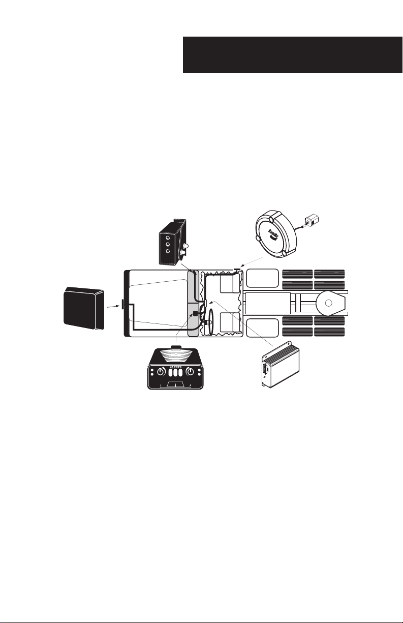
Bendix™ VORAD® EVT-300™ System Components
The Bendix™ VORAD® EVT-300™ Collision Warning System is comprised of four
main components: the Antenna Assembly, Central Processing Unit, Driver Display
Unit, and the Interconnecting Harness. Two components, the side sensor and side
sensor display, are optional. Each of the components are shown in their approximate
location on a vehicle (see Figure 1 below), and their functions are described in the
following paragraphs.
Figure 1
Antenna Assembly
The Antenna Assembly located on the front of the vehicle, transmits and receives
low power, high frequency radar signals. The transmitted radar signals are refl ected
off objects in front of the vehicle and are received back at the Antenna Assembly.
The Antenna Assembly compares the difference between the transmitted and
received signals; converts this information into a digital format; and transmits it to
the Central Processing Unit (see page 6) for additional processing. The Antenna
Assembly is usually mounted in the center of the bumper. This mounting location
ensures that the radar beam is aimed directly in front of the vehicle. The Antenna
Assembly simultaneously monitors up to 20 objects within a 350 feet (106 m) range,
whether moving or stationary.
5
Page 10

Component Description
Central Processing Unit
The Central Processing Unit (CPU) is the electronic control unit for the Bendix™
VORAD® EVT-300™ Collision Warning System. The CPU and Antenna Assembly are
programmable through a slot located in the opposite end from the cable connection
on the CPU (system parameters can be set with a Pro-Link™ Diagnostic Tool or
ServiceRanger 2.8). The CPU compiles information from the Antenna Assembly,
Engine Control Unit, Speedometer, optional Side Sensor (see page 7), Brake, and
Turn Signal Circuits to produce audible and visual warnings.
The CPU can be located in a variety of places, depending upon the orientation of
the CPU inside the vehicle in which it is installed. Typical locations are on the vehicle
fi rewall, underneath the dashboard, or behind the driver’s seat.
Driver Display Unit
The Driver Display Unit contains controls and indicators related to system operation.
The Driver Display Unit controls system power-up, speaker volume, range for
vehicle warnings, and headway thresholds for the Bendix™ SmartCruise® system.
A slot is also provided at the front bottom edge of the Driver Display Unit to insert
the optional Driver Identifi cation Card (see page 15). Driver Display Unit indicator
lights illuminate to indicate system power, system failure, absence of the Driver
Identifi cation Card, SmartCruise system enabled, and multiple stages of warning
levels.
A light sensor in the face of the Driver Display Unit adjusts indicator brightness with
changes in ambient light. The Driver Display Unit also contains a small speaker that
provides audible alert tones. The alert tones are sounded when the vehicle is closing
on an object, or if an object is detected by the Side Sensor and the turn signal is
activated for a lane change. Additionally, the speaker provides informational tones
such as volume level, system failures, and the Driver Identifi cation Card related
tones.
The Driver Display Unit mounts on top of, or is recessed in, the dashboard in an area
that is easily visible and accessible to the driver.
In certain applications there may not be a Driver Display Unit installed. The
information that is normally displayed on the Driver Display Unit may be included on
an OEM-installed integrated dashboard display. Consult the OEM literature for each
of these integrated systems for proper operation.
6
Page 11
Component Description
Central
Processing Unit
Antenna
Assembly
Side Sensor
Display
Side
Sensor
Driver
Display Unit
P2 SOD
BlindSpotter
®
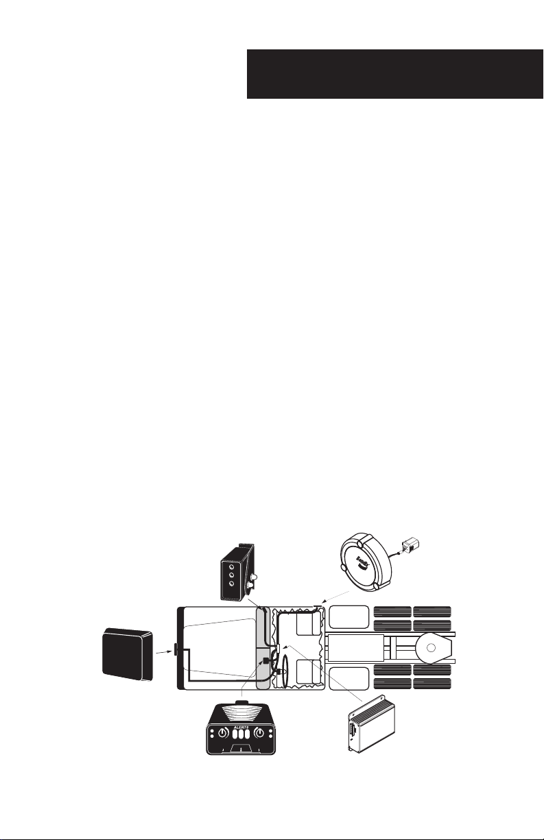
Side Sensor (Optional)
The Side Sensor is also a radar device that senses objects from two (2) to ten (10)
feet (.6 - 3 m) from the side of the vehicle in a blind spot area on either side of the
vehicle. This information is provided to the Central Processing Unit for processing;
to activate the illumination of appropriate indicator lamps; and to sound appropriate
alarms. Side Sensor(s) are generally mounted on the right side of the vehicle, at or
near a blind spot area (see fi gure 2). The vehicle can be confi gured to have a Side
Sensor on each side, left or right, or with two sensors located on the same side.
Side Sensor Display (Optional)
The Side Sensor Display contains red and yellow indicator lights that denote whether
or not the Side Sensor is detecting an object. The yellow indicator light is illuminated
when there is no object within the Side Sensor detection zone. When the Side
Sensor detects an object, the red indicator light illuminates and the yellow indicator
light goes off. The red light also illuminates when the Side Sensor has failed. The
red and yellow lights may both illuminate simultaneously during system start-up, and
in certain heavy rain conditions. The Side Sensor may not be able to detect objects
in heavy rain. A light sensor in the Side Sensor display adjusts indicator brightness
with changes in ambient light.
The Side Sensor Display is generally mounted to the right side A-pillar (see fi gure 2)
on the inside of the vehicle, easily visible by the driver, and usually along the same
line-of-sight as the side mirror.
Figure 2
7
Page 12

Controls Overview
FAIL
ON
S/C
Warning Level
Range
Volume
Green, SmartCruise/Accident
Reconstruction
Light Sensor
Red
Orange
Yellow
Driver
Identification
Card Slot
Red, System
Failure
Green,
Power ON/
Driver Identification
Card Status
Volume Control
Power ON/OFF
Speaker
Range Control/
Accident Recorder
Yellow,
No Vehicle Detected
Indicator Light
Red,
Vehicle Detected
Indicator Light
Light Sensor
Bendix™ VORAD® EVT-300™ System Controls
Driver Display Unit
All controls for the Bendix VORAD EVT-300 Collision Warning System are located
on the Driver Display Unit, or on the dash if your vehicle has an integrated display.
System controls and indicators are located on the Driver Display Unit. The optional
Side Sensor Display indicates the status of the optional Side Sensor.
Controls and indicators for the Driver Display Unit are shown below (see fi gure 3) and
described on pages 9 through 13. Indicators for the Side Sensor Display are shown
below (see fi gure 4) and described on page 14.
Driver Display Unit
8
Figure 3
Side Sensor Display Unit (Optional)
Figure 4
Page 13

FAIL
ON
S/C
Warning Level
Range
Volume
Green, SmartCruise/Accident
Reconstruction
Light Sensor
Red
Orange
Yellow
Driver
Identification
Card Slot
Red, System
Failure
Green,
Power ON/
Driver Identification
Card Status
Volume Control
Power ON/OFF
Speaker
Range Control/
Accident Recorder
Driver Display Indicators
Driver Display Indicators
Figure 5
Item Description
Green, Power-On/
Driver’s Identifi cation
Card Status*
Volume Control* and
Power On/Off
Speaker
NOTE: Items marked with an asterisk (*) can be changed (confi gured), by a
Technician, by using ServiceRanger 2.8, a PC-based service support tool.
Illuminates after power is applied to the system and the
power-on self test (described on page 16) is complete.
The green “ON” light may blink continuously if the
Driver’s Identifi cation Card is not installed, (the Driver
ID Card is an optional feature) and card alarm might be
enabled*. (See Figure 5)
When pushed in until a distinctive click is heard and/
or felt, this turns the power on or off* if enabled.
Adjusts the volume of the Driver Display Unit speaker
if enabled. Activates “Failure Display Mode” when the
knob is pressed in and held for eight (8) seconds and
then released. (See Figure 5)
Located under the top cover of the Driver Display Unit.
Sounds audible tones to alert the driver of a possible
hazard. May be set to limit the volume to a minimum
level*. (See Figure 5)
9
Page 14

Driver Display Indicators
Range Control* and
Accident Recorder*
Red, System Failure
™
Green, Bendix
SmartCruise®*/
Accident
Reconstruction*
Light Sensor
When rotated from minimum to maximum*, and
not in Bendix
™
SmartCruise® system*, this control
knob provides range adjustment of the fi rst alert
(2 to 3 seconds) and the second alert (1.75 to 2
seconds). Function may be confi gured to prevent
range adjustment control* (See Figure 5). When
the SmartCruise system is selected, rotation of the
knob, from maximum to minimum, will change the
following interval from 2.25 to 3.25 seconds. Accident
reconstruction is initiated by pushing and holding this
knob for fi ve (5) seconds, thereby freezing the most
recent event data in half of the allocated memory. (See
“In Case of an Accident” page 26). (See Figure 5)
Illuminates when a problem has been detected in the
forward looking radar system. A pattern of fl ashes blink
out the faults that are stored in memory when activated
by holding in the volume control knob for fi ve seconds
(See “Diagnostic Features”, page 27). (See Figure 5)
Comes on when the SmartCruise system is enabled
and vehicle cruise control has been engaged. If
Accident Reconstruction* has been initiated to store
information, it will fl ash eight (8) times. After system
power-up and power-on LED test is completed and if
Accident Reconstruction information was previously
stored, the display will fl ash eight (8) times.
(See Figure 5)
Photo sensor senses ambient lighting and adjusts
intensity of the indicator lights accordingly, e.g.,
increases the brightness of the indicator lights during
daytime hours and decreases the brightness of
indicator lights at night. (See Figure 5)
NOTE: Items marked with an asterisk (*) can be changed (confi gured), by a
Technician, by using ServiceRanger 2.8, a PC-based service support tool.
10
Page 15

Driver Display Unit
FAIL
ON
S/C
Warning Level
Range
Volume
Green, SmartCruise/Accident
Reconstruction
Light Sensor
Red
Orange
Yellow
Driver
Identification
Card Slot
Red, System
Failure
Green,
Power ON/
Driver Identification
Card Status
Volume Control
Power ON/OFF
Speaker
Range Control/
Accident Recorder
Figure 6
CWS Alert Warning Levels
Driver Display Indicators
Figure 7
11
Page 16

Driver Display Indicators
Warning Level Descriptions
• Warnings are received only on a vehicle in your lane.
• Range is reduced on curved roads.
• Warnings are disabled in sharp turns and when the brake is applied.
• The distances and times below are based on setting the Driver Display
Unit “RANGE” knob to maximum.
As you approach a slower vehicle ahead:
• At 350 ft. (106 m) to the vehicle, the yellow indicator illuminates;
• At 3 seconds to the vehicle, the yellow, orange indicator illuminates;
• At 2 seconds to the vehicle, the yellow, and orange indicators illuminate
and a single beep will sound;
• At 1 second, to the vehicle, the yellow, orange, and red indicators
illuminate, accompanied by a double beep; and
• At 0.5 seconds to the vehicle ahead, the three indicators illuminate and the
beeps will be continuous.
If a faster moving vehicle pulls into your lane and accelerates away:
• If less than 0.5 seconds away, the three indicators illuminate with
continuous beeps;
• At 0.5 to 1 second away, three indicators illuminate and no beeps;
• At more than 1 second away, the red indicator will go out;
• At 3 seconds away, the orange indicator will go out; and
• At 350 ft. (106 m), the yellow indicator will go out.
Proximity Alert
If your vehicle rolls very slowly (less than 2 MPH (3 km/h)) toward any stationary
object – or if a vehicle in front rolls back toward your vehicle – the yellow indicator
lights and a warning double beep sounds when the forward vehicle is within 15 ft.
(4.5 m).
Stationary Object
If a stopped vehicle is within 220 feet (67 m), a warning tone sounds and all three
lights illuminate when less than 3 seconds away.
12
Page 17

Driver Display Indicators
FAIL
ON
S/C
Warning Level
Range
Volume
Green, SmartCruise/Accident
Reconstruction
Light Sensor
Red
Orange
Yellow
Driver
Identification
Card Slot
Red, System
Failure
Green,
Power ON/
Driver Identification
Card Status
Volume Control
Power ON/OFF
Speaker
Range Control/
Accident Recorder
Slow Moving Object
If a vehicle ahead is moving 20% slower than your vehicle and is within 220 feet
(67 m), a warning tone sounds and all three lights illuminate when your vehicle is
less than 3 seconds away.
Miscellaneous Tones
Light/Tones Description
Fail Light, One Low
Tone
One Tone
Double Tone
One Low Tone
Flashing On Light,
One continuous Tone
(Confi gurable)
Sounds when the system diagnostics detects a failure.
Each time the volume control is turned, a single tone is
sounded.
Driver Identifi cation Card is successfully read when
inserted into the slot.
Driver Identifi cation Card is unsuccessfully read when
inserted into the slot.
Repeats if the Driver Identifi cation Card is required and
is not inserted.
Driver Display Unit
Figure 8
13
Page 18

Side Sensor Indicators
Yellow,
No Vehicle Detected
Indicator Light
Red,
Vehicle Detected
Indicator Light
Light Sensor
Side Sensor Display Indicators
Figure 9
Light/Tones
Red/Triple Tone
Light Sensor
Yellow
Red and Yellow
14
Description
Indicator light illuminates after objects have been detected
by the Side Sensor(s), and remain in proximity for more than
one (1) second. When the right turn signal is activated and
the Side Sensor detects an object, the red indicator light
illuminates, and the Driver Display Unit speaker sounds a
triple tone. The Tone is sounded only once per activation
of the turn signal. (See Figure 9)
The photo sensor senses ambient light and increases the
brightness of the indicator lights during the daytime hours
and decreases the brightness at night. Takes ten seconds to
activate. (See Figure 9)
Indicator light stays on when no objects are detected by the
Side Sensor(s). (See Figure 9)
Indicates the Side Sensor is performing a start-up self-test or
there is a failure. (See Figure 9)
Page 19

Driver ID Card (Optional)
Driver Identifi cation Card
If the system confi guration requires a Driver Identifi cation Card, (see Figure 10), it
must be inserted into the slot provided on the front of the Driver Display Unit (see
Figure 8, page 13). After the system is powered on, insert the Card into the slot with
a smooth, steady, continuous motion. Allow approximately one (1) second to ensure
the bar code is read. A high-pitched confi rmation tone will sound when the card
is correctly scanned. The card should be removed and stored in a safe place until
required again. If the bar code is not scanned correctly, the system will sound one
low-pitched tone.
If the Card is not installed into the slot in the Driver Display Unit, when required, two
events can occur: the green “ON” light will fl ash continuously; or the green “ON”
light will fl ash continuously accompanied by a matching audible tone. This is a
confi gurable option.
Driver Identifi cation Card (Optional)
Figure 10
15
Page 20

Initial Start-Up
Bendix™ VORAD® EVT-300™ System Start-Up
WARNING: Be sure the vehicle is not moving during the initial self-test
conducted at vehicle start-up. If the vehicle is in motion, the system
may not operate properly. No collision warning system alerts will be
given by the EVT-300 system until all lights are extinguished after the
self-test is complete.
1. The EVT-300 system powers up when turning the vehicle ignition key to the run
position. All Driver Display Unit and Side Sensor indicator lights will illuminate
and stay on until the self-test is complete.
2. If the green “ON” indicator is fl ashing, insert the Driver Identifi cation Card (see
page 15) into the Driver Display Unit so the system can identify the driver of the
vehicle.
3. If the green “S/C” (Bendix™ SmartCruise®) light fl ashes eight (8) times after
the self-test is completed, an accident reconstruction event has been stored
in the system memory. The light will continue to fl ash eight (8) times during
every start-up until the event is cleared. Notify your management to assist you
with this procedure. If the event has been stored in error, the system software
should clear the system in 30 days.
4. If the “FAIL” indicator light (or headway control failure) illuminates and stays on
after the self-test or while driving, a component or system failure has occurred.
This may render the Bendix™ VORAD® system inoperable. If the Bendix™
SmartCruise® option is enabled and a failure occurs, the SmartCruise system
will no longer function (see page 25) until the fault has been corrected and the
ignition switch has been turned OFF and then back ON. Collision warning lights
and tones may still work correctly when the SmartCruise system failures occur
that are brought on by a component or system failure.
16
Page 21

Typical System Tracking
Detected but not alerted
Detected but not alerted
Critical Target
Detected but not alerted
Critical Target
Bendix™ VORAD® EVT-300™ System Vehicle Tracking
Straight Ahead Same Lane Tracking
The system’s same-line target discrimination capability eliminates detection of
nuisance objects in adjacent lanes.
Curved Same Line Tracking
While driving on curved roads, the same lane target discrimination is maintained
using the host vehicle turn rate information and vehicle azimuth (angle to object).
Due to limitations on the radar’s fi eld of view, maximum range is limited in sharp
turns.
17
Page 22

Special Road Situations
Bendix™ VORAD® EVT-300™ System Road Situations
WARNING: The Bendix VORAD EVT-300 Collision Warning System
will not warn of all possible hazards. Do not assume it is “all clear” if
no warning signals are indicated. This system is intended solely as a
driver aid, and not to be relied upon to operate a vehicle. Use the
EVT-300 system in conjunction with rear view mirrors and other
instrumentation to maintain safe vehicle operation.
Certain road situations can affect the system’s ability to detect objects. Curves, dips,
and hills on the road in front of the vehicle can affect detection. The radar system
may sound a warning when it detects an object in front of the vehicle even though
the driver may be planning to turn away, or stop, prior to reaching the object. What
follows illustrates some special road situations that must be taken into account.
Detecting Objects While Vehicle is in a Turn
Audible alarms will not sound with oncoming traffi c during very sharp right or left
hand turns of less than 750 feet (228 m) radius.
18
Page 23

Special Road Situations
Detected but not alerted
Critical Target
Detected but not alerted
Detecting Objects Alongside an Approaching Curve
When approaching a curve, warnings may sound and indicators may illuminate due
to objects – such as a parked car – on the side of a curved portion of the road in
direct line with the radar beam, until the vehicle is actually starting into the turn.
Detecting Elevated Obstacles
Some unusual road elevation angles may cause the system to detect overhead
signs or overpasses.
19
Page 24

Special Road Situations
Detecting Vehicles on the Other Side of a Hill
The system cannot detect vehicles over a hill. No audible alarm will sound until
objects are within the fi eld of view of the radar antenna.
Approaching a Steep Hill
The system cannot detect objects above its beam. Generally, the alarm does not
sound from the beam hitting the road surface.
20
Page 25

Special Road Situations
Side Sensor Coverage
Note that the optional Side Sensor(s) only detects object motion within its fi eld of
view. This view includes the 2 to 10 feet (.6 - 3 m) next to the vehicle.
Note: Vehicles outside of the fi eld of view will not be detected.
Side Sensor Range
The Side Sensor(s) range is set to detect vehicles in the adjacent lane two (2) to ten
(10) feet (.6 - 3 m) away.
Note: When a fi xed object maintains a continuous presence along the right side of
the vehicle (e.g. guard rails, construction walls, tunnels, bridges, etc.), the
“red” light on the optional Side Sensor display may remain illuminated.
21
Page 26

Bendix™ SmartCruise® System (Optional)
Bendix™ VORAD® EVT-300™ SmartCruise® System
(Optional)
The SmartCruise system is an optional enhancement to the Bendix VORAD
EVT-300 Collision Warning System. The SmartCruise system is activated whenever
the vehicle’s standard cruise control system is activated and the EVT-300 system is
powered on. When the SmartCruise system is active, the green “S/C” (SmartCruise)
light in the upper right corner of the Driver Display Unit will illuminate, or a headway
control indicator will be evident on an OEM-proprietary messaging center.
The “RANGE” control knob (see Figure 8, page 13) adjusts the Bendix SmartCruise
system’s “following intervals”. The SmartCruise system will either maintain the
selected following interval between the host vehicle and a vehicle ahead or, in the
case of no target vehicle, the set cruise control speed. The following interval takes
precedence over the set cruise control speed.
Listed below are descriptions of the most common situations encountered while
using the SmartCruise system.
• Cruise Control is On and No Vehicle is Detected
If no vehicle is present in front of the vehicle (or if present and
beyond the range of the EVT-300 system), the vehicle will maintain
the speed selected by the cruise control.
• Cruise Control is On and A Vehicle is Detected
The driver can adjust the SmartCruise system following interval from
2.25 to 3.25 seconds if enabled. See the table on next page for the
following interval (in seconds) versus the following interval in feet, at
various speeds.
WARNING: The Bendix SmartCruise system does not replace an
alert, trained driver. The SmartCruise system will not react to stationary
objects and cannot bring the vehicle to a complete stop. The driver still
needs to use good driving practices to avoid an accident.
22
Page 27

Bendix™ SmartCruise® System (Optional)
Following Intervals
Following
Following
Interval in
Seconds
2.25 165 (50) 182 (55) 198 (60) 214 (65)
2.50 183 (56) 202 (62) 220 (67) 238 (73)
2.75 202 (62) 222 (68) 242 (74) 262 (80)
3.00 220 (67) 242 (74) 264 (80) 286 (87)
3.25 238 (73) 262 (80) 286 (87) 309 (94)
Bendix™ SmartCruise® System On
• Normal Operation
Interval in
Feet (m)
at 50 MPH
As the Bendix™ VORAD®-equipped vehicle approaches a target
vehicle in the same line, the VORAD-equipped vehicle will slow to the
speed of the other vehicle and maintain the set following distance
interval at their speed. The speed reduction may be accomplished
by the engine ECM (Engine Control Module) issuing a command to
reduce fuel, and engaging the engine retarder.
WARNING: If your vehicle speed and the forward vehicle speed are
drastically different, the driver may need to apply the service brakes
to maintain a safe distance. As with cruise control, the SmartCruise
system must be reset after brakes have been applied.
Following
Interval in
Feet (m)
at 55 MPH
Following
Interval in
Feet (m)
at 60 MPH
Following
Interval in
Feet (m)
at 65 MPH
WARNING: If another vehicle in an adjacent lane cuts in front and
continues to the opposite lane, the SmartCruise system may not
respond.
23
Page 28

Bendix™ SmartCruise® System (Optional)
Cut In and Out
If the speed of the forward vehicle is faster than that of your vehicle, your vehicle
will continue to maintain its speed. However, if the speed of the forward vehicle is
less than your vehicle’s speed, the engine ECM will issue a command to reduce
fuel and may also engage the engine retarder. Once the target vehicle moves out of
your lane, your vehicle will restore the cruise control speed, or resume the following
interval if another forward vehicle is in the lane. Again, the driver may need to apply
the service brake to maintain a safe distance. The driver may also depress the
acceleration pedal at any time to override the SmartCruise® system.
Cut In and Stay
If a forward vehicle in an adjacent lane cuts in front of your vehicle and remains
there, the system will respond by slowing your vehicle to restore the set following
distance interval to the forward vehicle. The engine ECM will reduce fuel and may
also engage the engine retarder to accomplish this. As stated above, the driver may
need to apply the brake to maintain a safe distance.
Vehicle Ahead Changes Lane
When maintaining a following interval to a forward vehicle, and that vehicle moves
into an adjacent lane, the system will respond. If there is no other vehicle ahead (or
within the range of the system), your vehicle will accelerate to the set cruise speed.
If there is another vehicle ahead, your vehicle will restore the following distance
interval to that vehicle. As stated above, the driver may need to apply the brake to
maintain a safe distance.
The Bendix SmartCruise System and AutoShift™ Transmissions
Under any situation that causes the system to slow the vehicle, and the engine RPM
reaches a preset minimum, the vehicle’s AutoShift transmission will automatically
downshift. Similarly, any situation that causes the vehicle to accelerate and a preset
maximum engine RPM is reached, the AutoShift will upshift.
The Bendix SmartCruise System and Manual Transmissions
Under any situation that causes the system to slow the vehicle, and the engine RPM
reaches a preset minimum, the engine ECM will disengage cruise control and the
driver may need to manually downshift the transmission. If this happens, the vehicle
cruise control will need to be re-engaged (Resume or Set) before the SmartCruise
system will resume operation.
24
Page 29

Bendix™ SmartCruise® System (Optional)
Road Curves and the SmartCruise System
1. Gentle Curves
The SmartCruise system will continue to maintain a set following
interval in a gentle curve as long as the turn is greater than 750 feet
(228 m) radius.
2. Sharp Curves
When maintaining a set following interval, the system may lose track
of the forward vehicle. If this happens, your vehicle will maintain its
current speed. When the forward vehicle is again within the view of
the EVT-300 system, the SmartCruise system will restore the set
following interval. Refer to pages 17 through 21 for “Typical System
Tracking” and “Special Road Situations”.
Note: The previous paragraphs do not address all the possible driving situations that
the vehicle and driver may encounter while in SmartCruise.
SmartCruise System Failure
Cruise Control/SmartCruise System Fails to Operate
Due to the variety of engines available by OEM, the procedure to override this error
and return to normal cruise control must come from the engine manufacturer.
Note: The most widely used method among engine manufacturers is to toggle the
cruise control on/off switch two (2) times within 10 seconds starting from
the “ON” position. If this does not work, please contact your dealership or
maintenance personnel.
WARNING: The SmartCruise system is not a substitute for an alert,
trained driver. The driver is ultimately responsible for the safe operation
of the vehicle and the driver should fully understand the operating
characteristics of the SmartCruise system and take all necessary
actions to operate the vehicle in a safe manner.
25
Page 30

In Case of an Accident
FAIL
ON
S/C
Warning Level
Range
Volume
Driver Identification
Card Slot
Alerts
Range Control/
Accident Recorder
Accident Reconstruction Capability (Optional)
The Accident Recorder can store two segments of system data in the system’s
non-volatile memory. The fi rst of the two segments may be stored by pushing
and holding the “RANGE” knob on the Driver Display Unit for approximately fi ve
(5) seconds. Within six (6) seconds, the green “S/C” light will blink eight times,
confi rming storage of the data (see Figure 11). Subsequent pushing of the
“RANGE” knob will cause the system to respond with a “FAIL” tone. After the fi rst
segment is frozen, the second segment runs continuously recording system data
until the system is powered down.
The system’s Central Processing Unit must be returned to Bendix Commercial
Vehicle Systems to download and interpret the recorded data in the non-volatile
memory. This must be done before 30 days have elapsed, or the event will be
removed from the system memory. Before shipping the unit, contact Bendix at
1-800-247-2725. After confi rmation, ship the Central Processor Unit to Bendix,
Attn: Accident Reconstruction Specialist, 901 Cleveland Street, Elyria, OH 44035.
Figure 11
26
Page 31

Maintenance/Diagnostic
Preventive Maintenance
The only maintenance required should be to keep the Antenna Assembly and Side
Sensor clean of heavy buildups of mud, dirt, ice, and other materials that could
reduce the range of the system. Antenna alignment should also be checked if any
occurrence may have caused it to be misaligned.
WARNING: The system will not sense objects if the sensor view is
obstructed. Therefore, do not place objects in front of the system
sensors. Remove heavy buildups of mud, dirt, ice, and other materials.
WARNING: Proper alignment is critical to correct operation of the
system (See BW2863 for Antenna Assembly Alignment procedure).
WARNING: Be sure the vehicle is not moving during the initial self-test
conducted at vehicle start-up. If the vehicle is in motion, the system
may not operate properly. No collision warning system alerts will be
given by the EVT-300 system until all lights are extinguished after the
self-test is complete.
Diagnostic Features
The system performs testing on a continuous basis. Every 15 seconds, the results of
these tests are evaluated by the Central Processing Unit to determine whether or not
to report a failure. If a failure occurs within the front radar system, the red “FAIL” light
on the Driver Display Unit will illuminate continuously as long as the failure is active,
and the associated failure code is stored in the Central Processing Unit memory until
maintenance personnel are able to check the system.
The Bendix™ VORAD® EVT-300 system can indicate active and inactive fault codes
stored in the Central Processing Unit memory when it is placed into its “Failure
Display Mode”. Inactive fault codes are faults which have occurred and have selfcorrected. Active faults are faults that are still present. These fault codes provide
the driver the ability to record the system fault during a trip and call either the
maintenance department or Bendix Commercial Vehicle Systems for assistance.
When placed into its “Failure Display Mode” (see “How to Activate Failure Display
Mode” on page 28), specifi c fault codes are indicated by a pattern of fl ashes blinked
out on the Driver Display Unit’s red “FAIL” light indicator.
27
Page 32

Failure Display Mode
How to Activate Failure Display Mode
1. Press in and hold the Driver Display Unit “VOLUME” knob for at least fi ve
(5) seconds. If the knob is released before fi ve (5) seconds has lapsed,
the system will turn off. After fi ve (5) seconds the Driver Display Unit’s red
“FAIL” indicator light begins to blink out the failures. If there are no faults
found, the Driver Display Unit will fl ash a 41 code. At the conclusion of
fl ashing the fault codes, the system will fl ash a 41 code.
2. To read active fault codes, position the Driver Display Unit “RANGE”
knob to the left of center and only active codes will be sent to the “FAIL”
indicator light. Position the Driver Display Unit “RANGE” knob to the right
of center and inactive faults will fl ash the “FAIL” indicator light.
3. Each fault code consists of a two digit number. A pause (approximately 3/4
of a second in duration) separates the blinking of the fi rst and second digit
of the fault code. Example: Fault code 22 is indicated by two (2) blinks,
a 3/4 second pause, and two (2) more blinks. In this case, the fault code
of 22, suspects a faulty “LT Turn Signal”. There is a pause of three (3)
seconds between each fl ash code fault. If there are no faults, a code 41
will be fl ashed.
4. Additional fault codes are blinked out at approximately eight (8) second
intervals. After all fault codes have been displayed, a code 41 will be
fl ashed.
28
Page 33

Failure Display Mode
Fault Code Chart
Fault Code Suspect Failure
11 Central Processing Unit
12 Central Processing Unit
13 Driver Display Unit
14 Antenna Assembly
15 Right Side Sensor
16 Left Side Sensor
21 Right Turn Signal
22 Left Turn Signal
23 Brake Input
24 Speed Input
25 SmartCruise Compatibility
31 J-1587
32 J-1939
33 VBUS
34 Driver Display Unit
35 Antenna Assembly
41 No Fault or End of Fault Codes
Report any failures indicated by the Driver Display Unit or Side Sensor Display to
maintenance personnel for service. If the red “FAIL” indicator light comes on while
driving, turn the system off (if available), and do not use until it has been repaired.
Side Sensor failures will illuminate either the red or yellow lights on the Side Sensor
Display. The lights will remain illuminated as long as a failure is detected.
If you have any further questions regarding the Bendix
1-800-247-2725 in the U.S., Canada, and Mexico; contact your OE dealer in Europe.
™
VORAD® system, call
29
Page 34

Page 35

Page 36

BW2861 ©2011 Bendix Commercial Vehicle Systems LLC, a member of the Knorr-Bremse Group
All Rights Reserved • 10/11
 Loading...