

Page 1

Bendix™ VORAD® Collision Warning System
Troubleshooting Guide
Bendix™ VORAD® Collision Warning System
BW2849 (Formerly VOTS0030)
December 2011
EVT-300
Page 2
Fault Isolation Procedures
General Warnings
Before starting a vehicle:
1. Sit in the driver’s seat.
2. Place the vehicle in neutral.
3. Set the parking brake.
4. Disengage the clutch.
Before working on the vehicle or leaving the cab with the engine
running:
1. Place the vehicle in neutral.
2. Set the parking brake.
3. Block the wheels.
Do not operate the vehicle if the alternator lamp is lit or if the
gauges indicate low voltage.
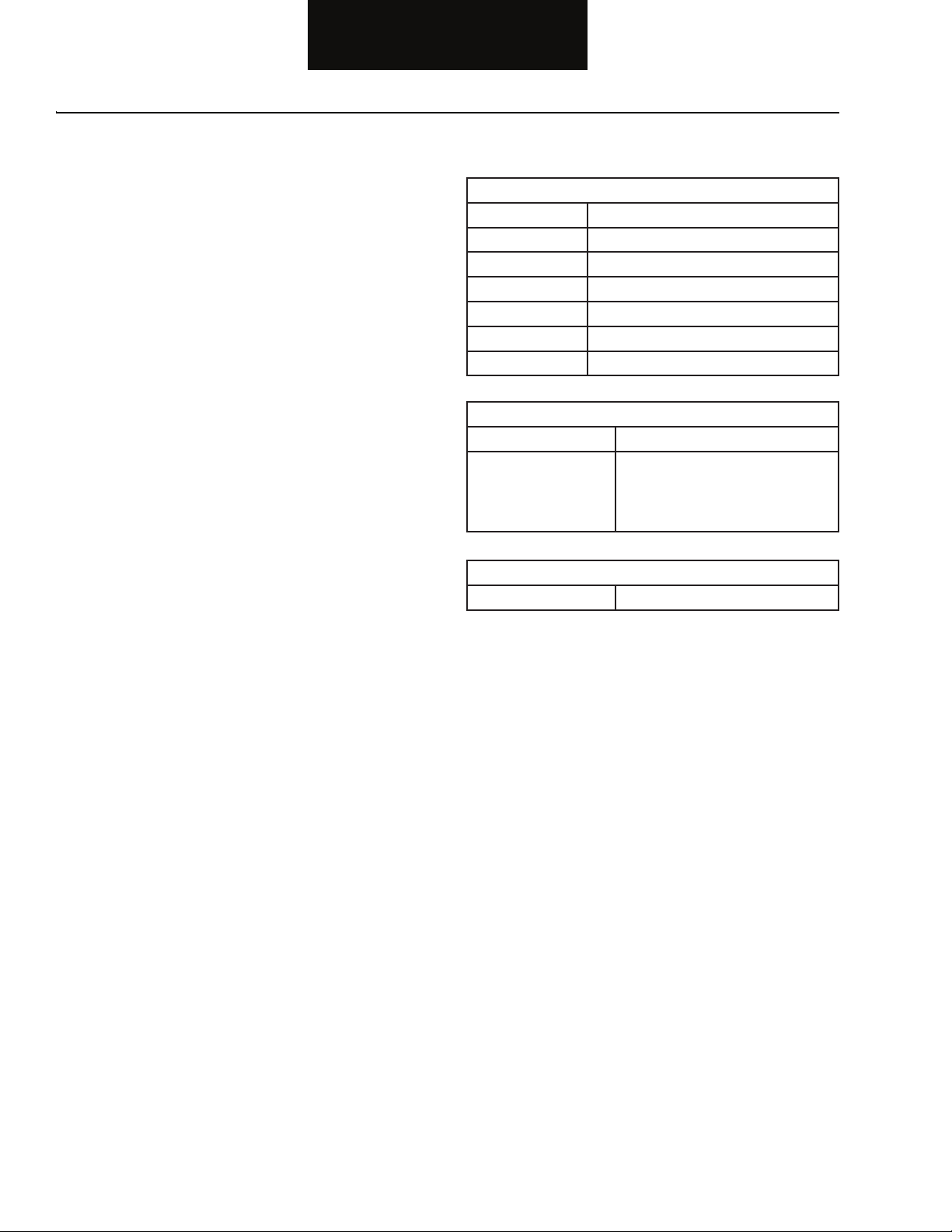
Suggested Tools
NEXIQ Technologies 1-800-639-6774 www.NEXIQ.com
Part No. Description
104004 Pro-Link GRAPHIQ
208040 Multi-Protocol Cartridge (MPC)
804001 MPC Eaton System Software
501003A Data Cable
405048 6- and 9-Pin Deutsch Diagnostic Adapter
125032 USB Link™ Vehicle Link Adapter
Bendix 1-800-AIR-BRAKE www.bendix.com
Part No. Description
ServiceRanger 2.8 PC-based Diagnostics
For EVT-300 specifi c ServiceRanger
questions call Bendix at
1-800-AIR-BRAKE
Standard Commercial Product
Volt/OHM Meter (VOM)
™
Related Publications
For more information call 1-800-AIR-BRAKE in the U.S., Canada,
and Mexico.
Page 3

Table of Contents
Section 1: Introduction
Diagnostic Procedure ........................................................ 1-1
Fault Code Retrieval and Clearing ..................................... 1-2
Fault Code Isolation Procedure Index................................ 1-3
Driving Techniques ............................................................ 1-4
Symptom-Driven Index ...................................................... 1-7
Section 2: Fault Isolation Procedures
Pretests
Electrical Pretest ............................................................... 2-1
Power-Up Sequence Test .................................................. 2-5
Component and System Codes
Component Code: 11, 12 (SID 254, FMI 4,12)
Central Processing Unit (CPU) ................................ 2-19
Component Code: 13, 34 (SID 9, FMI 2, 4, 5, 12)
Driver Display Unit ................................................... 2-21
Component Code: 14, 35 (SID 1, 2, FMI 2, 12, 14)
Antenna Assembly .................................................. 2-29
Component Code: 15 (SID 10, FMI 2)
Right Side Sensor ................................................... 2-37
Component Code: 16 (SID 11, FMI 2)
Left Side Sensor ...................................................... 2-43
Component Code: 21 (SID 7, FMI 2)
Right Turn Signal ..................................................... 2-49
Component Code: 22 (SID 8, FMI 2)
Left Turn Signal ....................................................... 2-53
Component Code: 23 (SID 3, FMI 2)
Brake Input Error ..................................................... 2-57
Component Code: 24 (SID 6, FMI 2)
Speed Input Error .................................................... 2-63
Component Code: 25, 32 (SID 231, FMI 2, 12,14)
J-1939 Signal and Cruise Signal ............................. 2-67
Component Code: 31 (SID 250, FMI 2)
J-1587 Data Link ..................................................... 2-75
Component Code: 33 (SID 248, FMI 12)
VBUS ...................................................................... 2-81
Section 3: Symptom Isolation Procedures
Symptom Tests
Antenna Not Detecting Targets .......................................... 3-1
Antenna Target Detection Test .......................................... 3-2
Side Sensor Not Detecting Targets ................................... 3-3
Side Sensor Detection Test ............................................... 3-4
Driver Card Not Reading ................................................. 3-11
Driver Detection Test ....................................................... 3-12
Appendix
VORAD® Wiring Diagram ..................................................A-1
Fault Code Tree ................................................................. A-3
Table of Contents
Table of Contents
Page 4
Fault Isolation Procedures
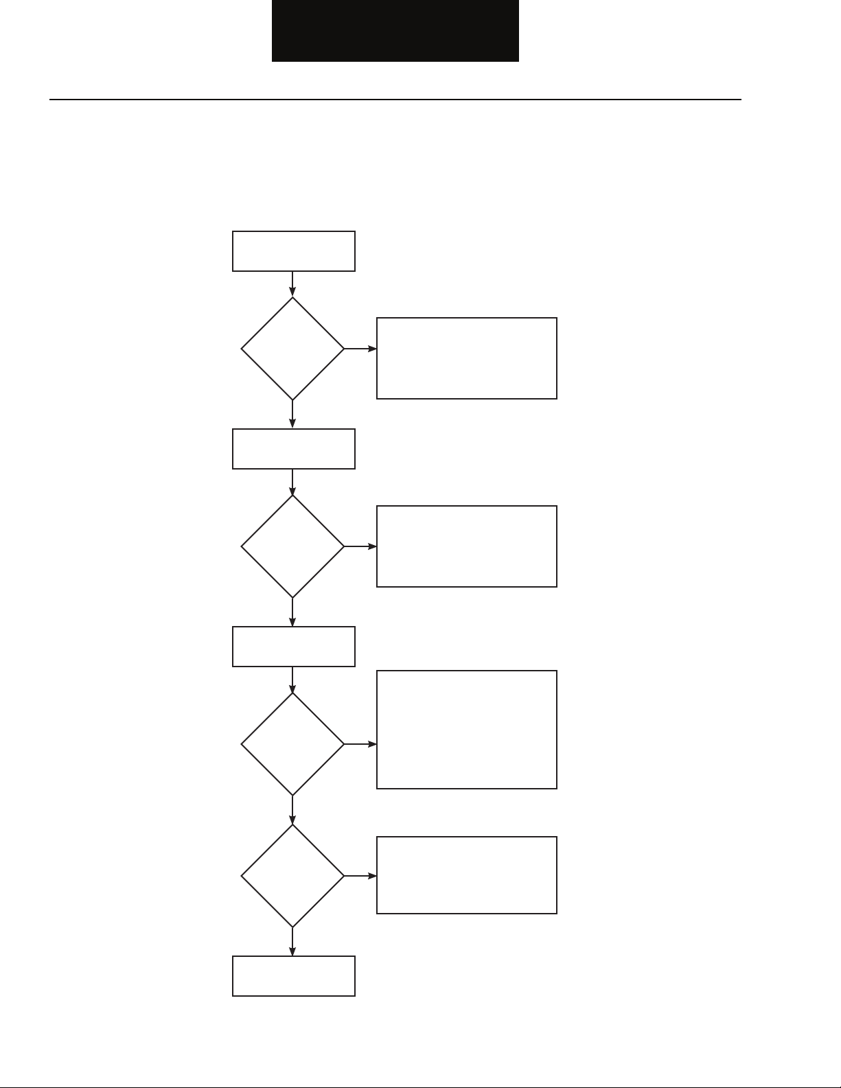
Diagnostic Procedure
Follow the fl owchart below for all Bendix™ VORAD® system failures. Perform tests and procedures as directed by the fl owchart.
Key On
Is the
Driver Display
Unit lamp lit?
(For Freightliner IDI,
skip this step.)
YES
NO
Perform Electrical Pretest
•
(page 2-1)
Perform Power-up Sequence Test
•
(page 2-5)
Retrieve Active Codes
(page 1-3)
Active
Codes?
NO
Retrieve Active Codes
(page 1-3)
Inactive
Codes?
NO
YES
YES
Perform Electrical Pretest
•
(page 2-1)
Refer to the Fault Code Isolation
•
Procedure Index to select a fault
code isolation procedure (page 1-4)
Perform Electrical Pretest (page 2-1)
•
Record and clear codes (page 1-3)
Perform Driving Techniques to
•
reproduce the inactive fault code
(page 1-5)
Refer to the Fault Code Isolation
Procedure Index to select a fault
code isolation procedure (page 1-4)
1-1
Symptom?
NO
Test Complete.
YES
Perform Electrical Pretest
•
(page 2-1)
Refer to the Symptom-Driven
•
Index to select a symptom isolation
procedure (page 1-8)
Page 5

Fault Code Retrieval and Clearing
Fault Isolation Procedures
RETRIEVING FAULT CODES
Note: Retrieve Bendix™ VORAD® system fault codes by enabling
the VORAD system’s self-diagnostic mode.
You can also use a PC-based Service Tool, such as ServiceRanger
2.8, or a Pro-Link tool, to retrieve VORAD system fault codes.
1. Put the vehicle in neutral.
2. Set the parking brake.
3. To activate Failure Display Mode, press in and hold
the Driver Display Unit “VOLUME” knob while turning the
key on.
Note: For software versions 013 and higher, hold “VOLUME” knob
in for 8 seconds.
4. Wait until the Driver Display Unit’s red “FAIL” indicator
light begins fl ashing two-digit fault codes and release
the volume knob. If no fault codes are found, the Driver
Display Unit will fl ash a code 41. At the conclusion of
fl ashing the fault codes, the system will fl ash a code 41.
5. TO READ ACTIVE FAULT CODES: Position the Driver
Display Unit “RANGE” knob to the left of center and only
active codes will be sent to the “FAIL” indicator light.
CLEARING FAULT CODES
1. Inactive fault codes must be cleared using a PC-based
Service Tool, such as ServiceRanger 2.8, or a Pro-Link
tool.
2. Active fault codes change to inactive fault codes when
the fault has been corrected. Clear inactive fault codes.
3. Turn key off and allow system to power down.
Service Procedure
4. Start vehicle and verify no fault codes reoccur.
6. TO READ INACTIVE FAULT CODES: Position the Driver
Display Unit “RANGE” knob to the right of center and
only inactive codes will be sent to the “FAIL” indicator
light.
7. Observe the sequence of fl ashes on the indicator lamp
and record the codes. A one to two second pause
separates each stored code, and at the conclusion of
fl ashing the fault codes, the system will fl ash a code 41.
The sequence automatically repeats after all codes have
been fl ashed.
1-2
Page 6
Fault Isolation Procedures
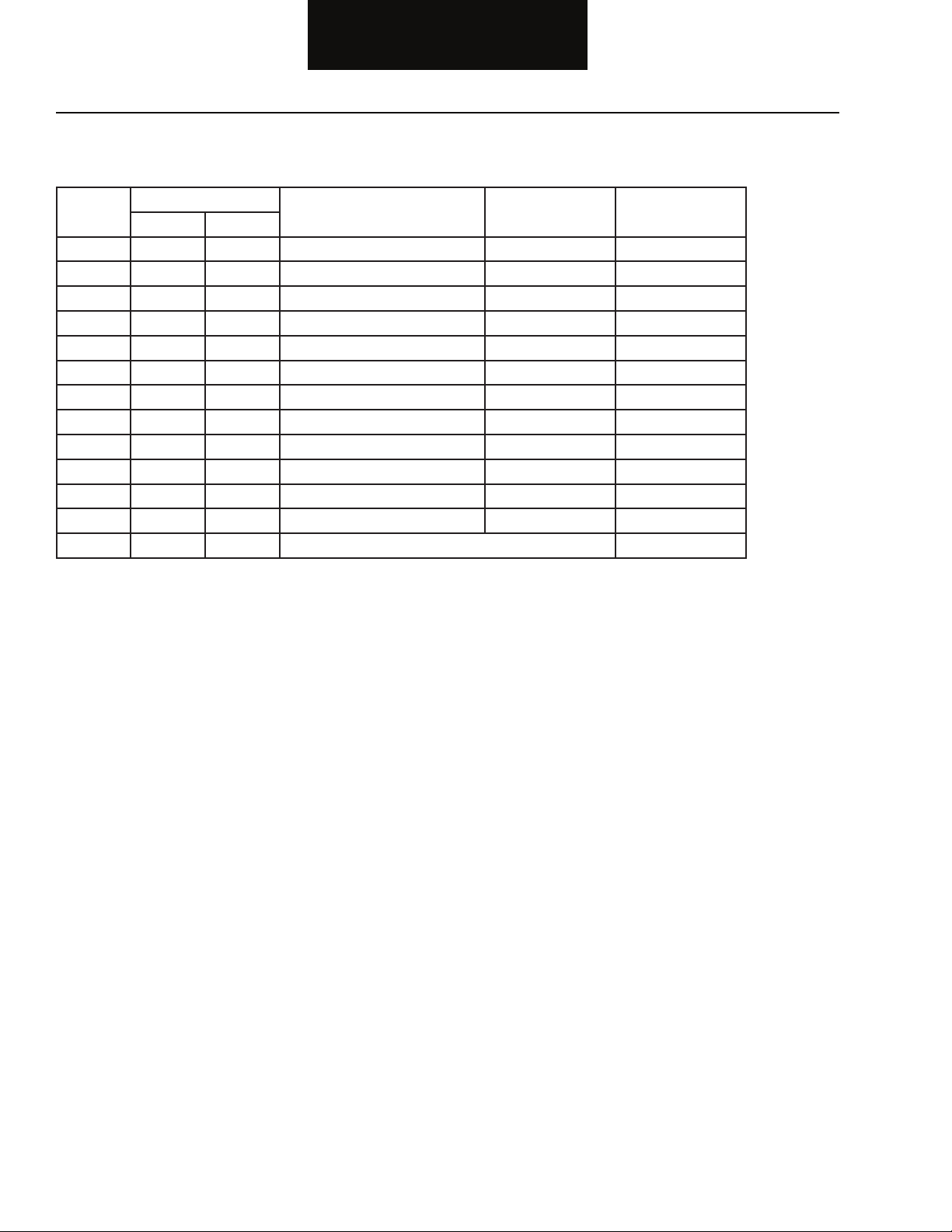
Fault Code Isolation Procedure Index
Fault
Codes
11, 12 254 4,12 Central Processing Unit Component 2 - 19
13, 34 9 2,4,5,12 Driver Display Unit Component 2 - 21
14, 35 1,2 2,12,14 Antenna Assembly Component 2 - 29
15 10 2 Right Side Sensor Component 2 - 37
16 11 2 Left Side Sensor Component 2 - 43
21 7 2 Right Turn Signal Component 2 - 49
22 8 2 Left Turn Signal Component 2 - 53
23 3 2 Brake Input Signal Component 2 - 57
24 6 2 Speed Input Signal Component 2 - 63
25, 32 231 2,12,14 J-1939 Data Link Signal System 2 - 67
31 250 2 J-1587 Data Link Signal System 2 - 75
33 248 12 VBUS Component 2 - 81
41 No Fault or End of Fault Codes
Hand-Held Codes
Description Type of Code Page NumberSID FMI
1-3
Page 7

Driving Techniques
Fault Isolation Procedures
Fault
Codes
11, 12 254 4,12 Central Processing Unit Component Key on. If the fault is present, the
13, 34 9 2,4,5,12 Driver Display Unit
14, 35 1,2 2,12,14 Antenna Component Key on. If the fault is present, the
15 10 2 Right Side Sensor Component Key on. If the fault is present, the
16 11 2 Left Side Sensor Component Key on. If the fault is present, the
Hand-Held Codes
Description Type of Code Driving TechniqueSID FMI
(Not applicable for
Freightliner IDI.)
system should automatically detect the
problem and set the code. If the fault
is not present at key on, operate the
vehicle and attempt to duplicate the
driving conditions that triggered the
fault code. Possible triggers include
heat and vibration.
Component Key on. If the fault is present, the
system should automatically detect the
problem and set the code. If the fault
is not present at key on, operate the
vehicle and attempt to duplicate the
driving conditions that triggered the
fault code. Possible triggers include
heat and vibration.
system should automatically detect the
problem and set the code. If the fault
is not present at key on, operate the
vehicle and attempt to duplicate the
driving conditions that triggered the
fault code. Possible triggers include
heat and vibration.
system should automatically detect the
problem and set the code. If the fault
is not present at key on, operate the
vehicle and attempt to duplicate the
driving conditions that triggered the
fault code. Possible triggers include
heat and vibration.
system should automatically detect the
problem and set the code. If the fault
is not present at key on, operate the
vehicle and attempt to duplicate the
driving conditions that triggered the
fault code. Possible triggers include
heat and vibration.
Service Procedure
1-4
Page 8

Fault Isolation Procedures
Fault
Codes
21 7 2 Right Turn Signal System Key on. If the fault is present, the
22 8 2 Left Turn Signal System Key on. If the fault is present, the
23 3 2 Brake Input Signal System Key on. Apply service brake for
24 6 2 Speed Input Signal System Select a forward gear and drive at a
25, 32 231 2,12,14 J-1939 Data Link Signal System Key on. If the fault is present, the
Hand-Held Codes
Description Type of Code Driving TechniqueSID FMI
system should automatically detect the
problem and set the code. If the fault
is not present at key on, operate the
vehicle and attempt to duplicate the
driving conditions that triggered the
fault code. Possible triggers include
heat and vibration.
system should automatically detect the
problem and set the code. If the fault
is not present at key on, operate the
vehicle and attempt to duplicate the
driving conditions that triggered the
fault code. Possible triggers include
heat and vibration.
a minimum of 8 seconds. If the
fault is present, the system should
automatically detect the problem and
set the code. If the fault is not present at
key on, operate the vehicle and attempt
to duplicate the driving conditions
that triggered the fault code. Possible
triggers include heat and vibration.
steady speed no slower than 10 MPH.
It may be necessary to operate the
vehicle for a prolonged period of time
if the cause of failure is related to heat
and vibration.
system should automatically detect the
problem and set the code. If the fault
is not present at key on, operate the
vehicle and attempt to duplicate the
driving conditions that triggered the
fault code. Possible triggers include
heat, vibration, and varying levels of
throttle demand. It may take up to 75
seconds to set this fault.
1-5
Page 9

Fault Isolation Procedures
Fault
Codes
31 250 2 J-1587 Data Link Signal System Key on. If the fault is present, the
33 248 12 VBUS Component Key on. If the fault is present, the
41 No Fault or End of Fault
Hand-Held Codes
Description Type of Code Driving TechniqueSID FMI
system should automatically detect the
problem and set the code. If the fault
is not present at key on, operate the
vehicle and attempt to duplicate the
driving conditions that triggered the
fault code. Possible triggers include
heat, vibration, and varying levels of
throttle demand. It may take up to 75
seconds to set this fault.
Codes
Service Procedure
1-6
Page 10

Fault Isolation Procedures
Symptom-Driving Index
Symptom Isolation Procedure Page Number
Antenna Not Detecting Targets Antenna Not Detecting Targets 3 - 1
Side Sensor Not Detecting Targets Side Sensor Not Detecting Targets 3 - 3
Driver Card Not Reading Driver Card Not Reading 3 - 11
1-7
Page 11

Fault Isolation Procedures
Service Procedure
This page left blank intentionally.
1-8
Page 12
Electrical Pretest
Harness
Fault Isolation Procedures
Overview
The pretest does not relate to any specifi c fault code, but must
be completed before performing Fault Code Isolation Table
procedures. The pretest verifi es the basic electrical inputs before
testing individual circuits.
Detection
There is no detection process specifi cally for the basic electrical
supply. However, failures of this type are generally detected by the
Bendix™ VORAD® system or the driver as some other type of fault
code or symptom.
Fallback
There is no fallback for the electrical pretest, however, it may affect
other systems.
Required Tools
• Basic Hand Tools
• Digital Volt/Ohm Meter
• Troubleshooting Guide
Possible Causes
This pretest can be used for any of the following:
• Corroded Power Contacts
• Blown Fuse
• Wiring Harness
• Low Batteries
2-1
Page 13

Fault Isolation Procedures
VOLT
V ACOM
Electrical Pretest
Step A Procedure Condition Action
1. Key off.
2. Inspect starter/battery
connections for integrity.
3. Measure voltage across
battery.
If voltage is 11 to 13 volts
on a 12 volt system or 22 to
26 on a 24 volt system
If voltage is outside of
range
Go to Step B.
Repair or replace batteries and
charging system as required.
Repeat this step.
Electrical Pretest
2-2
Page 14
Fault Isolation Procedures
OHMS
GROUND
V ACOM
1
CD
2
3
4
5
6
7
8
9
10
11
12
13
14
16
15
Electrical Pretest, continued
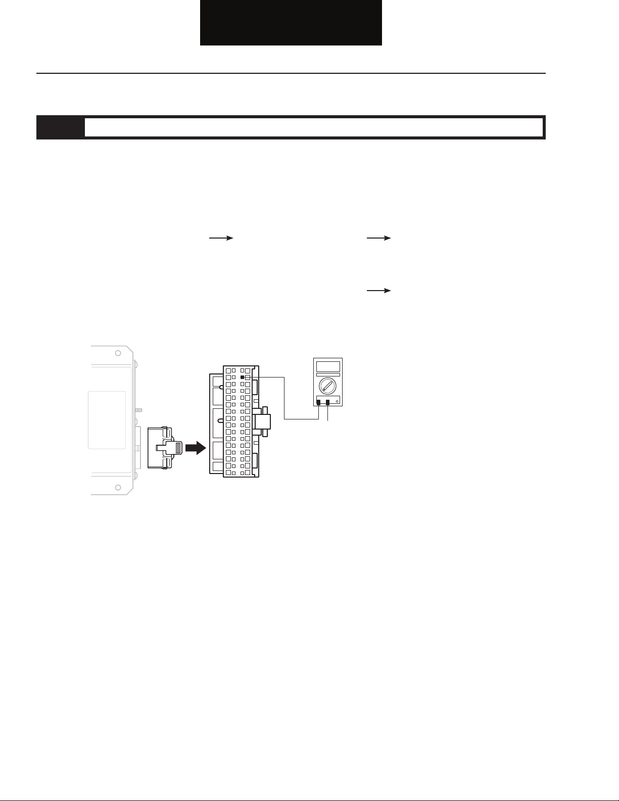
Step B Procedure Condition Action
1. Key off.
2. Disconnect negative (-) battery
cable.
3. Disconnect 32-way connector
from Central Processing Unit.
4. Measure resistance
between 32-way
connector pin C-2 and
ground.
If resistance is 0 to .5 ohms
If resistance is outside of
range
Go to Step C.
Repair ground path for Bendix™
VORAD® system. Go to Step A.
2-3
Page 15

Fault Isolation Procedures
VOLT
V ACOM
1
CD
2
3
4
5
6
7
8
9
10
11
12
13
14
16
15
Electrical Pretest, continued
Step C Procedure Condition Action
1. Key off.
2. Connect negative (-) battery
cable.
3. Key on.
4. Measure voltage
between 32-way
connector pin C-1 and
C-2.
If voltage is within .6 volts
of battery voltage
If voltage is outside of
range
Test complete.
Repair power path for Bendix™
VORAD® system. Fuse may be blown.
Reconnect all connectors. Go to
Step A.
Electrical Pretest
2-4
Page 16
Power-Up Sequence Test
Harness
Driver
Display Unit
Central
Processing Unit
Fault Isolation Procedures
Overview
A failure during the power-up self-check indicates a failure of the
Central Processing Unit.
Detection
The power-up self-check is performed automatically each time the
key is turned on. Turn the key on and watch the Driver Display Unit.
If lights on the Driver Display Unit remain on after 15 seconds, or
never come on, the self-check has failed. NOTE: Not applicable for
Freightliner IDI (Integrated Dash Interface).
Fallback
If self-check fails, the product can not perform any operations.
Required Tools
• Digital Volt/Ohm Meter
Possible Causes
• Central Processing Unit
• Driver Display Unit
• Vehicle Harness
2-5
Page 17

Fault Isolation Procedures
VOLT
V ACOM
D C B A
Power-Up Sequence Test
Step A Procedure Condition Action
1. Before performing this test, the
Electrical Pretest must pass.
2. Key on.
3. Observe the Driver
Display Unit.
If lights turn on the go off
after approximately 15
Test complete.
seconds
Note: Not applicable for
Freightliner IDI
If lights fail to turn on
If lights turn on and stay on
Go to Step B.
Go to Step C.
Step B Procedure Condition Action
1. Key on.
2. Disconnect the 4-way connector
from the Driver Display Unit.
Note: Not applicable for
Freightliner IDI.
3. Measure voltage
between pins C and D
on the Driver Display
Unit 4-way connector.
If voltage is between 7.0
and 7.5 volts
Go to Step C.
Power-Up Sequence Test
If voltage is outside of
range
Go to Step G.
2-6
Page 18

Fault Isolation Procedures
1
CD
2
3
4
5
6
7
8
9
10
11
12
13
14
16
15
1
CD
2
3
4
5
6
7
8
9
10
11
12
13
14
16
15
D C B A
OHMS
V ACOM
OHMS
GROUND
V ACOM
Power-Up Sequence Test, continued
Step C Procedure Condition Action
1. Key off.
2. Disconnect Central Processing
Unit 32-way connector.
3. Measure resistance between:
• Central Processing
Unit 32-way
connector pin D3
and Driver Display
4-way connector
pin D.
• Central Processing
Unit 32-way
connector pin D3
and ground.
If resistance between D3 and
pin D is 0 to .3 ohms and if
resistance between pin D3
and ground is more than 10K
ohms or open circuit [OL]
If any of the above conditions
are not met
Go to Step D.
Repair OEM wiring harness between
Driver Display Unit and Central
Processing Unit. Go to Step V.
2-7
Page 19

Fault Isolation Procedures
1
CD
2
3
4
5
6
7
8
9
10
11
12
13
14
16
15
1
CD
2
3
4
5
6
7
8
9
10
11
12
13
14
16
15
D C B A
OHMS
V ACOM
OHMS
GROUND
V ACOM
Power-Up Sequence Test, continued
Step D Procedure Condition Action
1. Key off.
2. Measure resistance between:
• Central Processing
Unit 32-way
connector pin D4
and Driver Display
4-way connector
pin C.
• Central Processing
Unit 32-way
connector pin D4
and ground.
If resistance between pin D4
and pin C is 0 to .3 ohms and
if resistance between pin D4
and ground is more than 10K
ohms or open circuit [OL]
If any of the above conditions
are not met
Go to Step E.
Repair OEM wiring harness between
Driver Display Unit and Central
Processing Unit. Go to Step V.
Power-Up Sequence Test
2-8
Page 20
Fault Isolation Procedures
OHMS
V ACOM
OHMS
GROUND
V ACOM
1
CD
2
3
4
5
6
7
8
9
10
11
12
13
14
16
15
1
CD
2
3
4
5
6
7
8
9
10
11
12
13
14
16
15
D C B A
Power-Up Sequence Test, continued
Step E Procedure Condition Action
1. Key off.
2. Disconnect Central Processing
Unit 32-way connector.
3. Measure resistance between:
• Central Processing
Unit 32-way
connector pin D5
and Driver Display
4-way connector
pin B.
• Central Processing
Unit 32-way
connector pin D5
and ground.
If resistance between pin D5
and pin B is 0 to .3 ohms and if
resistance between pin D5
and ground is more than 10K
ohms or open circuit [OL]
If any of the above conditions
are not met
Go to Step F.
Repair OEM wiring harness between
Driver Display Unit and Central
Processing Unit. Go to Step V.
2-9
Page 21
Fault Isolation Procedures
OHMS
V ACOM
OHMS
GROUND
V ACOM
1
CD
2
3
4
5
6
7
8
9
10
11
12
13
14
16
15
1
CD
2
3
4
5
6
7
8
9
10
11
12
13
14
16
15
D C B A
Power-Up Sequence Test, continued
Step F Procedure Condition Action
1. Key off.
2. Measure resistance between:
• Central Processing
Unit 32-way
connector pin D6
and Driver Display
4-way connector
pin A.
• Central Processing
Unit 32-way
connector pin D6
and ground.
If resistance between pin D6
and pin A is 0 to .3 ohms and
if resistance between pin D6
and ground is more than 10K
ohms or open circuit [OL]
If any of the above conditions
are not met
Go to Step G.
Repair OEM wiring harness between
Driver Display Unit and Central
Processing Unit. Go to Step V.
Power-Up Sequence Test
2-10
Page 22

Fault Isolation Procedures
1
CD
2
3
4
5
6
7
8
9
10
11
12
13
14
16
15
OHMS
V ACOM
OHMS
GROUND
V ACOM
1
2 3
4
1
CD
2
3
4
5
6
7
8
9
10
11
12
13
14
16
15
Power-Up Sequence Test, continued
Step G Procedure Condition Action
1. Key off.
2. Disconnect Central Processing
Unit 32-way connector and Front
Antenna 4-way connector.
3. Measure resistance between:
• Central Processing
Unit 32-way
connector pin C3
and Antenna
4-way connector
pin 4.
• Central Processing
Unit 32-way
connector pin C3
and ground.
If resistance between pin C3 and
pin 4 is 0 to .3 ohms and if
resistance between pin C3
and ground is more than 10K
ohms or open circuit [OL]
If any of the above conditions
are not met
Go to Step H.
Repair OEM wiring harness between
Antenna and Central Processing Unit.
Go to Step V.
2-11
Page 23

Fault Isolation Procedures
1
CD
2
3
4
5
6
7
8
9
10
11
12
13
14
16
15
1
CD
2
3
4
5
6
7
8
9
10
11
12
13
14
16
15
OHMS
V ACOM
OHMS
GROUND
V ACOM
1
2
3
4
Power-Up Sequence Test, continued
Step H Procedure Condition Action
1. Key off.
2. Measure resistance between:
• Central Processing
Unit 32-way
connector pin C4
and Antenna
4-way connector
pin 3.
• Central Processing
Unit 32-way
connector and pin C4
and ground.
If resistance between pin C4
and pin 3 is 0 to .3 ohms and
if resistance between pin C4
and ground is more than 10K
ohms or open circuit [OL]
If any of the above conditions
are not met
Go to Step I.
Repair OEM wiring harness between
Antenna and Central Processing Unit.
Go to Step V.
Power-Up Sequence Test
2-12
Page 24
Fault Isolation Procedures
1
CD
2
3
4
5
6
7
8
9
10
11
12
13
14
16
15
1
CD
2
3
4
5
6
7
8
9
10
11
12
13
14
16
15
OHMS
V ACOM
OHMS
GROUND
V ACOM
1
2 3
4
Power-Up Sequence Test, continued
Step I Procedure Condition Action
1. Key off.
2. Disconnect Central Processing
Unit 32-way connector.
3. Measure resistance between:
• Central Processing
Unit 32-way
connector pin C5
and Antenna 4-way
connector pin 2.
• Central Processing
Unit 32-way
connector pin
C5 and ground.
If resistance between pin C5 and
pin 2 is 0 to .3 ohms and if
resistance between pin C5
and ground is more than 10K
ohms or open circuit [OL]
If any of the above conditions
are not met
Go to Step J.
Repair OEM wiring harness between
Antenna and the Central Processing
Unit. Go to Step V.
2-13
Page 25

Fault Isolation Procedures
1
CD
2
3
4
5
6
7
8
9
10
11
12
13
14
16
15
1
CD
2
3
4
5
6
7
8
9
10
11
12
13
14
16
15
OHMS
GROUND
V ACOM
OHMS
V ACOM
1
2 3
4
Power-Up Sequence Test, continued
Step J Procedure Condition Action
1. Key off.
2. Measure resistance between:
• Central Processing
Unit 32-way
connector pin C6
and Antenna 4-way
connector pin 1.
• Central Processing
Unit 32-way
connector and pin C6
and ground.
If resistance between pin C6
and pin 1 is 0 to .3 ohms and
if resistance between pin C6
and ground is more than 10K
ohms or open circuit [OL]
If any of the above conditions
are not met
Go to Step K.
Repair OEM wiring harness between
Antenna and Central Processing Unit.
Go to Step V.
Power-Up Sequence Test
2-14
Page 26

Fault Isolation Procedures
Power-Up Sequence Test, continued
Step K Procedure Condition Action
1. Key off.
2. Reconnect Central Processing Unit
32-way connector.
3. Connect spare Front Antenna
to 4-way connector.
4. Key on.
5. Check error codes. If no error codes
If error codes
Replace Antenna.
Go to Step V.
Replace Central Processing Unit.
Go to Step L.
2-15
Page 27

Fault Isolation Procedures
Power-Up Sequence Test, continued
Step L Procedure Condition Action
1. Key off.
2. Connect spare Driver
Display to 4-way
connector.
3. Key on.
4. Check error codes. If no error codes
If error codes
Replace Driver Display Unit.
Go to Step V.
Go to Step A.
Find error in testing.
Power-Up Sequence Test
2-16
Page 28

Fault Isolation Procedures
Power-Up Sequence Test, continued
Step V Procedure Condition Action
1. Key off.
2. Reconnect all connectors.
3. Key on.
4. Clear Codes. See “Fault Code
Retrieval and Clearing” on page 2.
5. Use Driving Techniques to attempt
to set a code. See “Driving
Techniques” on page 4.
6. Check for Codes. See
“Fault Code Retrieval and
Clearing” on page 2.
Note: If problem still exists there
may be a software
compatibility problem.
Contact your Bendix
representative.
If no codes
If code appears
Test complete.
See “Fault Code Isolation
Procedure Index” on page 3.
2-17
Page 29

Power-Up Sequence Test, continued
Fault Isolation Procedures
This page left blank intentionally.
Power-Up Sequence Test
2-18
Page 30

Component Code: 11, 12
Central
Processing Unit
(SID 254, FMI 4, 12)
Central Processing Unit (CPU)
Fault Isolation Procedures
Overview
This fault indicates an internal failure of the Central Processing
Unit.
Detection
The Central Processing Unit checks the program memory every
time the key is turned on. If the Central Processing Unit is able to
detect a failure within its own memory, it sets these fault codes.
Fallback
This fault causes a failure of the Bendix™ VORAD® system.
Required Tools
• Basic Hand Tools
• Troubleshooting Guide
Possible Causes
• Central Processing Unit
2-19
Page 31

Fault Isolation Procedures
Code 11, 12 (SID 254, FMI 4, 12), Central Processing Unit (CPU)
Step A Procedure Condition Action
1. Key off.
2. Retrieve codes. If code 11 is active
If code 11 is inactive
Replace Central Processing Unit.
Test complete.
(SID 254, FMI 4, 12)
Code 11, 12
2-20
Page 32

Component Code: 13, 34
Harness
Driver
Display Unit
Central
Processing Unit
(SID 9, FMI 2, 4, 5, 12)
Driver Display Unit
Fault Isolation Procedures
Overview
This fault code indicates an electrical failure of the Driver Display
Unit.
Detection
Starting at key on and throughout the operation, the Central
Processing Unit constantly monitors the communication with the
Driver Display Unit. If a communication fault occurs for more than
fi ve seconds, fault code 13 is set.
Fallback
This fault causes a failure of the Bendix™ VORAD® system.
Required Tools
• Basic Hand Tools
• Troubleshooting Guide
• Digital Volt/Ohm Meter
• Data Link Tester
• PC-based or Hand-held Diagnostic Tool
Possible Causes
This fault code can be caused by any of the following:
• OEM Harness
• Driver Display Unit
• Central Processing Unit
2-21
Page 33

Fault Isolation Procedures
VOLT
V ACOM
D C B A
Code 13, 34 (SID 9, FMI 2, 4, 5, 12) Driver Display Unit
Step A Procedure Condition Action
1. Key off.
(SID 9, FMI 2, 4, 5, 12)
Code 13, 34
2. Using a PC-based or
If FMI 2, 4, or 5 exist
Go to Step B.
Hand-held Diagnostic
Tool check for FMI
(Failure Mode Identifi ers)
codes.
Note: If a diagnostic tool is not
available, go to Step B.
If FMI 12 exists
Replace Driver Display Unit.
Go to Step V.
Step B Procedure Condition Action
1. Key off.
2. Unplug the Driver Display
Unit 4-way connector.
3. Key on.
4. Measure voltage between
Driver Display Unit 4-way
connector pin D and pin C.
If voltage is 7.0 to 7.5 volts
If voltage is outside of range
Go to Step E.
Go to Step C.
2-22
Page 34

Fault Isolation Procedures
1
CD
2
3
4
5
6
7
8
9
10
11
12
13
14
16
15
1
CD
2
3
4
5
6
7
8
9
10
11
12
13
14
16
15
D C B A
OHMS
V ACOM
OHMS
GROUND
V ACOM
Code 13, 34 (SID 9, FMI 2, 4, 5, 12) Driver Display Unit, continued
Step C Procedure Condition Action
1. Key off.
2. Disconnect Central Processing
Unit 32-way connector.
3. Measure resistance between:
• Central Processing
Unit 32-way
connector pin D3
and Driver Display
4-way connector
pin D.
• Central Processing
Unit 32-way
connector pin D3
and ground.
If resistance between D3 and
D is 0 to .3 ohms and if
resistance between pin D3
and ground is more than 10K
ohms or open circuit [OL]
If any of the above conditions
are not met
Go to Step D.
Repair OEM wiring harness
between Driver Display Unit
and Central Processing Unit.
Go to Step V.
2-23
Page 35

Fault Isolation Procedures
1
CD
2
3
4
5
6
7
8
9
10
11
12
13
14
16
15
1
CD
2
3
4
5
6
7
8
9
10
11
12
13
14
16
15
D C B A
OHMS
V ACOM
OHMS
GROUND
V ACOM
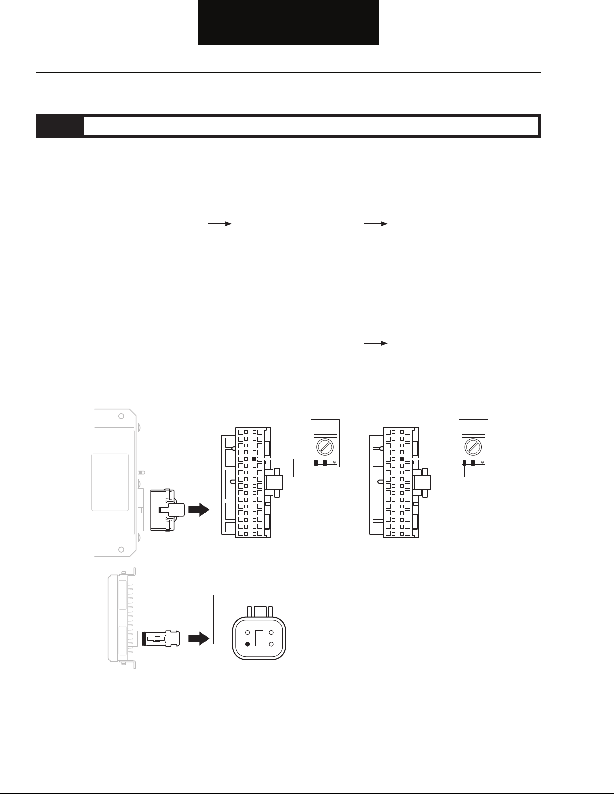
Code 13, 34 (SID 9, FMI 2, 4, 5, 12) Driver Display Unit, continued
Step D Procedure Condition Action
1. Key off.
2. Measure resistance between:
• Central Processing
Unit 32-way
connector pin D4
and Driver Display
4-way connector
pin C.
• Central Processing
Unit 32-way
connector pin D4
and ground.
If resistance between pin D4
and pin C is 0 to .3 ohms and
if resistance between pin D4
and ground is more than 10K
ohms or open circuit [OL]
If any of the above conditions
are not met
Replace Central Processing
Unit. Go to Step V.
Repair OEM wiring harness
between Driver Display Unit
and Central Processing Unit.
Go to Step V.
(SID 9, FMI 2, 4, 5,12)
Code 13, 34
2-24
Page 36

Fault Isolation Procedures
OHMS
V ACOM
OHMS
GROUND
V ACOM
1
CD
2
3
4
5
6
7
8
9
10
11
12
13
14
16
15
1
CD
2
3
4
5
6
7
8
9
10
11
12
13
14
16
15
D C B A
Code 13, 34 (SID 9, FMI 2, 4, 5, 12) Driver Display Unit, continued
Step E Procedure Condition Action
1. Key off.
2. Disconnect Central Processing
Unit 32-way connector.
3. Measure resistance between:
• Central Processing
Unit 32-way
connector pin D5
and Driver Display
4-way connector
pin B.
• Central Processing
Unit 32-way
connector pin D5
and ground.
If resistance between pin D5
and pin B is 0 to .3 ohms and
if resistance between pin D5
and ground is more than 10K
ohms or open circuit [OL]
If any of the above conditions
are not met
Go to Step F.
Repair OEM wiring harness
between Driver Display Unit
and Central Processing Unit.
Go to Step V.
2-25
Page 37

Fault Isolation Procedures
OHMS
V ACOM
OHMS
GROUND
V ACOM
1
CD
2
3
4
5
6
7
8
9
10
11
12
13
14
16
15
1
CD
2
3
4
5
6
7
8
9
10
11
12
13
14
16
15
D C B A
Code 13, 34 (SID 9, FMI 2, 4, 5, 12) Driver Display Unit, continued
Step F Procedure Condition Action
1. Key off.
2. Measure resistance between:
(SID 9, FMI 2, 4, 5, 12)
Code 13, 34
• Central Processing
Unit 32-way
connector pin D6
and Driver Display
4-way connector
pin A.
• Central Processing
Unit pin D6 and
ground.
If resistance between pin D6
and pin A is 0 to .3 ohms and
if resistance between pin D6
and ground is more than 10K
ohms or open circuit [OL]
If any of the above conditions
are not met
Go to Step G.
Repair OEM wiring harness
between Driver Display Unit
and Central Processing Unit.
Go to Step V.
2-26
Page 38

Fault Isolation Procedures
Code 13, 34 (SID 9, FMI 2, 4, 5, 12) Driver Display Unit, continued
Step G Procedure Condition Action
1. Key off.
2. Reconnect Central Processing
Unit 32-way connector.
3. Connect spare Driver
Display to 4-way
connector.
4. Key on.
5. Check error codes. If no error codes
If error codes
Replace Driver Display Unit.
Go to Step V.
Replace Central Processing
Unit. Go to Step V.
2-27
Page 39

Fault Isolation Procedures
Code 13, 34 (SID 9, FMI 2, 4, 5, 12) Driver Display Unit, continued
Step V Procedure Condition Action
1. Key off.
2. Reconnect all connectors.
3. Key on.
4. Clear Codes. See “Fault Code
Retrieval and Clearing” on
page 1 - 2.
5. Use Driving Techniques to attempt
to reset the code. See “Driving
Techniques” on page 1 - 4.
(SID 9, FMI 2, 4, 5, 12)
Code 13, 34
6. Check for Codes. See
“Fault Code Retrieval and
Clearing” on page 1 - 2.
If no codes
If code 13 or 34 appears
If code other than 13 or 34
appears
Test complete.
Return to Step A to fi nd error
in testing.
See “Fault Code Isolation
Procedure Index” on
page 1 - 3.
2-28
Page 40

Component Code: 14, 35
Harness
Antenna
Central
Processing Unit
(SID 1, 2, FMI 2, 12, 14)
Antenna Assembly
Fault Isolation Procedures
Overview
This fault code indicates the Antenna and Central Processing Unit
are unable to communicate.
Detection
Starting at key on and throughout the operation, the Central
Processing Unit constantly monitors the communication with the
Antenna. If a communication fault occurs for more than 5 seconds,
fault code 14 is set.
Fallback
This fault causes a failure of the Bendix™ VORAD® system.
Required Tools
• Basic Hand Tools
• Troubleshooting Guide
• Digital Volt/Ohm Meter
• PC-based or Hand-held Diagnostic Tool
Possible Causes
This fault code can be caused by any of the following:
• Antenna Assembly
• OEM Harness
• Central Processing Unit
• Central Processing Unit / Antenna Software
Incompatibility
2-29
Page 41

Fault Isolation Procedures
VOLT
V ACOM
1
2 3
4
Code 14, 35 (SID 1, 2, FMI 2, 12, 14) Antenna
Step A Procedure Condition Action
1. Key off.
2. Using a PC-based or
If FMI 2 exists
Go to Step B.
Hand-held Diagnostic
Tool check for FMI
(Failure Mode Identifi er)
codes.
Note: If a diagnostic tool is not
If FMI 12 exists
Go to Step B.
available, go to Step B.
If FMI 14 exists
There may be a software
compatibility problem.
Contact your Bendix
representative.
Step B Procedure Condition Action
1. Key off.
2. Unplug the Antenna 4-way
connector.
3. Key on.
4. Measure voltage between
Antenna 4-way connector
pin 3 and pin 4.
If voltage is 7.0 to 7.5 volts
Go to Step E.
(SID 1, 2, FMI 2, 12, 14)
Code 14, 35
If voltage is outside of range
Go to Step C.
2-30
Page 42

Fault Isolation Procedures
1
CD
2
3
4
5
6
7
8
9
10
11
12
13
14
16
15
OHMS
V ACOM
OHMS
GROUND
V ACOM
1
2 3
4
1
CD
2
3
4
5
6
7
8
9
10
11
12
13
14
16
15
Code 14, 35 (SID 1, 2, FMI 2, 12, 14) Antenna, continued
Step C Procedure Condition Action
1. Key off.
2. Disconnect Central Processing
Unit 32-way connector.
3. Measure resistance between:
• Central Processing
Unit 32-way
connector pin C3
and Antenna 4-way
connector pin 4.
• Central Processing
Unit 32-way
connector pin C3
and ground.
If resistance between C3 and
pin 4 is 0 to .3 ohms and if
resistance between pin C3
and ground is more than 10K
ohms or open circuit [OL]
If any of the above conditions
are not met
Go to Step D.
Repair OEM wiring harness
between Antenna and Central
Processing Unit. Go to Step V.
2-31
Page 43

Fault Isolation Procedures
1
CD
2
3
4
5
6
7
8
9
10
11
12
13
14
16
15
1
CD
2
3
4
5
6
7
8
9
10
11
12
13
14
16
15
OHMS
V ACOM
OHMS
GROUND
V ACOM
1
2
3
4
Code 14, 35 (SID 1, 2, FMI 2, 12, 14) Antenna, continued
Step D Procedure Condition Action
1. Key off.
2. Measure resistance between:
• Central Processing
Unit 32-way
connector pin C4
and Antenna 4-way
connector pin 3.
• Central Processing
Unit 32-way
connector pin C4
and ground.
If resistance between pin C4
and pin 3 is 0 to .3 ohms and
if resistance between pin C4
and ground is more than 10K
ohms or open circuit [OL]
If any of the above conditions
are not met
Replace Central Processing
Unit. Go to Step V.
(SID 1, 2, FMI 2, 12, 14)
Code 14, 35
Repair OEM wiring harness
between Antenna and Central
Processing Unit. Go to Step V.
2-32
Page 44

Fault Isolation Procedures
1
CD
2
3
4
5
6
7
8
9
10
11
12
13
14
16
15
1
CD
2
3
4
5
6
7
8
9
10
11
12
13
14
16
15
OHMS
V ACOM
OHMS
GROUND
V ACOM
1
2 3
4
Code 14, 35 (SID 1, 2, FMI 2, 12, 14) Antenna, continued
Step E Procedure Condition Action
1. Key off.
2. Disconnect Central Processing
Unit 32-way connector.
3. Measure resistance between:
• Central Processing
Unit 32-way
connector pin C5
and Antenna 4-way
connector pin 2.
• Central Processing
Unit 32-way
connector and pin C5
and ground.
If resistance between pin C5
and pin 2 is 0 to .3 ohms and
if resistance between pin C5
and ground is more than 10K
ohms or open circuit [OL]
If any of the above conditions
are not met
Go to Step F.
Repair OEM wiring harness
between Antenna and the Central
Processing Unit. Go to Step V.
2-33
Page 45

Fault Isolation Procedures
1
CD
2
3
4
5
6
7
8
9
10
11
12
13
14
16
15
1
CD
2
3
4
5
6
7
8
9
10
11
12
13
14
16
15
OHMS
GROUND
V ACOM
OHMS
V ACOM
1
2 3
4
Code 14, 35 (SID 1, 2, FMI 2, 12, 14) Antenna, continued
Step F Procedure Condition Action
1. Key off.
2. Measure resistance between:
• Central Processing
Unit 32-way
connector pin C6
and Antenna 4-way
connector pin 1.
• Central Processing
Unit 32-way
connector pin C6
and ground.
If resistance between pin C6
and pin 1 is 0 to .3 ohms and
if resistance between pin C6
and ground is more than 10K
ohms or open circuit [OL]
If any of the above conditions
are not met
Go to Step G.
(SID 1, 2, FMI 2, 12, 14)
Code 14, 35
Repair OEM wiring harness
between Antenna and Central
Processing Unit. Go to Step V.
2-34
Page 46

Fault Isolation Procedures
Code 14, 35 (SID 1, 2, FMI 2, 12, 14) Antenna, continued
Step G Procedure Condition Action
1. Key off.
2. Reconnect Central Processing
Unit 32-way connector.
3. Connect spare Antenna
to 4-way connector.
4. Key on.
5. Check error codes. If no error codes
If error codes
Replace Antenna.
Go to Step V.
Replace Central Processing
Unit. Go to Step V.
2-35
Page 47

Fault Isolation Procedures
Code 14, 35 (SID 1, 2, FMI 2, 12, 14) Antenna, continued
Step V Procedure Condition Action
1. Key off.
2. Reconnect all connectors.
3. Key on.
4. Clear Codes. See “Fault Code
Retrieval and Clearing” on page
1 - 2.
(SID 1, 2, FMI 2, 12, 14)
5. Use Driving Techniques to attempt
to reset the code. See “Driving
Techniques” on page 1 - 4.
6. Check for Codes. See
“Fault Code Retrieval and
Clearing” on page 1 - 2.
Note: If problem still exists there
may be a software
compatibility problem.
Contact your Bendix
representative.
If no codes
If code 14 appears
If code other than 14 appears
Code 14, 35
Test complete.
Return to Step A to fi nd error
in testing.
See “Fault Code Isolation
Procedure Index” on page 1 - 3.
2-36
Page 48

Component Code: 15
Harness
Right
Side Sensor
Central
Processing Unit
(SID 10, FMI 2)
Right Side Sensor
Fault Isolation Procedures
Overview
This fault code indicates an electrical failure of the Right Side
Sensor.
Detection
Starting at key on and throughout the operation, the Central
Processing Unit constantly monitors the feedback from the Right
Side Sensor.
Fallback
This fault will not allow the Bendix™ VORAD® system to detect
objects on the right side of the vehicle.
Required Tools
• Basic Hand Tools
• Digital Volt/Ohm Meter
• Troubleshooting Guide
• PC-based or Hand-held Diagnostic Tool
Possible Causes
This fault code can be caused by any of the following:
• Wiring Harness
• Right Side Sensor
• Central Processing Unit
• System Confi guration
2-37
Page 49

Fault Isolation Procedures
VOLT
V ACOM
VOLT
V ACOM
B A
C
B A
C
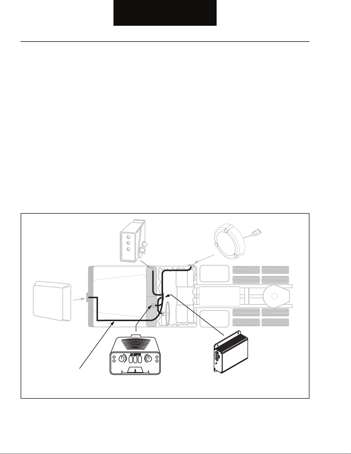
Code 15 (SID 10, FMI 2) Right Side Sensor
Step A Procedure Condition Action
1. Key off.
2. Is vehicle equipped with a
Right Side Sensor?
If the vehicle has a Right Side
Sensor
If the vehicle does not have a
Right Side Sensor
Go to Step B.
The Central Processing Unit
has been programmed for a
Right Side Sensor. With a
PC-based or Hand-held
Diagnostic Tool, place the
Right Side Sensor option in
“NO” position. Go to Step V.
Step B Procedure Condition Action
1. Key off.
2. Disconnect 3-way stub connector at
the Right Side Sensor.
3. Key on.
4. Measure voltage between:
• Pins A and B.
• Pins A and C.
If voltage between pins A
and B is 1.8 to 2.5 volts and
(SID 10, FMI 2)
Code 15
If voltage between pins A
and C is 7.0 to 7.5 volts
If voltage is outside of range
Replace Right Side Sensor.
Go to Step V.
Go to Step C.
2-38
Page 50

Fault Isolation Procedures
1
CD
2
3
4
5
6
7
8
9
10
11
12
13
14
16
15
1
CD
2
3
4
5
6
7
8
9
10
11
12
13
14
16
15
OHMS
V ACOM
OHMS
GROUND
V ACOM
B A
C
Code 15 (SID 10, FMI 2) Right Side Sensor, continued
Step C Procedure Condition Action
1. Key off.
2. Disconnect Central Processing
Unit 32-way connector.
3. Measure resistance between:
• 32-way pin C12
and 3-way pin C.
• 32-way pin C12
and ground.
If resistance between C12
and pin C is 0 to 0.3 ohms
and if resistance between
pin C12 and ground is more
than 10K ohms or open
circuit [OL]
If resistance is outside
of range
Go to Step D.
Repair OEM wiring harness
between Right Side Sensor and
Central Processing Unit.
Go to Step V.
2-39
Page 51

Fault Isolation Procedures
1
CD
2
3
4
5
6
7
8
9
10
11
12
13
14
16
15
1
CD
2
3
4
5
6
7
8
9
10
11
12
13
14
16
15
OHMS
V ACOM
OHMS
GROUND
V ACOM
AB
C
Code 15 (SID 10, FMI 2) Right Side Sensor, continued
Step D Procedure Condition Action
1. Key off.
2. Disconnect Central Processing Unit
32-way connector.
3. Measure resistance between:
• 32-way pin C13 and
3-way pin B.
• 32-way pin C13
and ground.
If resistance between pin C13
and pin B is 0 to 0.3 ohms and
if resistance between pin C13
and ground is more than 10K
ohms or open circuit [OL]
If resistance is outside
of range
Go to Step E.
Repair OEM wiring harness
between Right Side Sensor and
Central Processing Unit.
Go to Step V.
(SID 10, FMI 2)
Code 15
2-40
Page 52

Fault Isolation Procedures
1
CD
2
3
4
5
6
7
8
9
10
11
12
13
14
16
15
1
CD
2
3
4
5
6
7
8
9
10
11
12
13
14
16
15
OHMS
V ACOM
OHMS
GROUND
V ACOM
AB
C
Code 15 (SID 10, FMI 2) Right Side Sensor, continued
Step E Procedure Condition Action
1. Key off.
2. Disconnect Central Processing
Unit 32-way connector.
3. Measure resistance between:
• 32-way pin C14
and 3-way pin A.
• 32-way pin C14
and ground.
If resistance between C14
and pin A is 0 to 0.3 ohms
and if resistance between
pin C14 and ground is more
than 10K ohms or open
circuit [OL]
If resistance is outside
of range
Replace Central processing Unit.
Go to Step V.
Repair OEM wiring harness
between Right Side Sensor and
Central Processing Unit.
Go to Step V.
2-41
Page 53

Fault Isolation Procedures
Code 15 (SID 10, FMI 2) Right Side Sensor, continued
Step V Procedure Condition Action
1. Key off.
2. Reconnect all connectors.
3. Key on.
4. Clear Codes. See “Fault Code
Retrieval and Clearing” on
page 1 - 2.
5. Use Driving Techniques to attempt
to reset the code. See “Driving
Techniques” on page 1 - 4.
6. Check for Codes. See
“Fault Code Retrieval and
Clearing” on page 1 - 2.
If no codes
If code 15 appears
If code other than 15 appears
Test complete.
Return to Step A to fi nd error
in testing.
See “Fault Code Isolation
Procedure Index” on page 1 - 3.
(SID 10, FMI 2)
Code 15
2-42
Page 54

Component Code: 16
Harness
Left
Side Sensor
Central
Processing Unit
(SID 11, FMI 2)
Left Side Sensor
Fault Isolation Procedures
Overview
This fault code indicates an electrical failure of the Left Side Sensor.
Detection
Starting at key on and throughout the operation, the Central
Processing Unit constantly monitors the feedback from the Left
Side Sensor.
Fallback
This fault will not allow the Bendix™ VORAD® system to detect
objects on the left side of the vehicle.
Required Tools
• Basic Hand Tools
• Digital Volt/Ohm Meter
• Troubleshooting Guide
• PC-based or Hand-held Diagnostic Tool
Possible Causes
This fault code can be caused by any of the following:
• Wiring Harness
• Left Side Sensor
• Central Processing Unit
• System Confi guration
2-43
Page 55

Fault Isolation Procedures
VOLT
V ACOM
VOLT
V ACOM
B A
C
B A
C
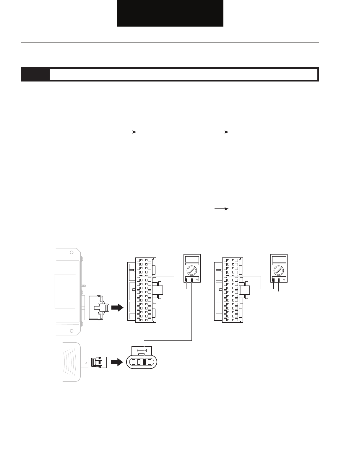
Code 16 (SID 11, FMI 2) Left Side Sensor
Step A Procedure Condition Action
1. Key off.
2. Is vehicle equipped with a
Left Side Sensor?
If the vehicle has a Left Side
Sensor
If the vehicle does not have a
Left Side Sensor
Go to Step B.
The Central Processing Unit
has been programmed for a
Left Side Sensor. With a
PC-based or Hand-held
Diagnostic Tool, place the
Left Side Sensor option in
“NO” position. Go to Step V.
Step B Procedure Condition Action
1. Key off.
2. Disconnect 3-way stub connector
at the Left Side Sensor.
3. Key on.
4. Measure voltage between:
• Pins A and B.
• Pins A and C.
If voltage between pins A
and B is 1.8 to 2.5 volts and
If voltage between pins A
and C is 7 to 7.5 volts
If voltage is outside of range
Replace Left Side Sensor.
Go to Step V.
Go to Step C.
(SID 11, FMI 2)
Code 16
2-44
Page 56

Fault Isolation Procedures
OHMS
V ACOM
OHMS
GROUND
V ACOM
1
CD
2
3
4
5
6
7
8
9
10
11
12
13
14
16
15
1
CD
2
3
4
5
6
7
8
9
10
11
12
13
14
16
15
B A
C
Code 16 (SID 11, FMI 2) Left Side Sensor, continued
Step C Procedure Condition Action
1. Key off.
2. Disconnect Central Processing
Unit 32-way connector.
3. Measure resistance between:
• 32-way pin D12
and 3-way pin C.
• 32-way pin D12
and ground.
If resistance between D12
and pin C is 0 to 0.3 ohms
and if resistance between
pin D12 and ground is more
than 10K ohms or open
circuit [OL]
If resistance is out of range
Go to Step D.
Repair OEM wiring harness
between Left Side Sensor and
Central Processing Unit.
Go to Step V.
2-45
Page 57

Fault Isolation Procedures
OHMS
V ACOM
OHMS
GROUND
V ACOM
1
CD
2
3
4
5
6
7
8
9
10
11
12
13
14
16
15
1
CD
2
3
4
5
6
7
8
9
10
11
12
13
14
16
15
B A
C
Code 16 (SID 11, FMI 2) Left Side Sensor, continued
Step D Procedure Condition Action
1. Key off.
2. Disconnect Central Processing
Unit 32-way connector.
3. Measure resistance between:
• 32-way pin D13 and
3-way pin B.
• 32-way pin D13
and ground.
If resistance between D13
and pin B is 0 to 0.3 ohms and
if resistance between pin D13
and ground is more than 10K
ohms or open circuit [OL]
If resistance is out of range
Go to Step E.
Repair OEM wiring harness
between Left Side Sensor and
Central Processing Unit.
Go to Step V.
(SID 11, FMI 2)
Code 16
2-46
Page 58

Fault Isolation Procedures
OHMS
V ACOM
OHMS
GROUND
V ACOM
1
CD
2
3
4
5
6
7
8
9
10
11
12
13
14
16
15
1
CD
2
3
4
5
6
7
8
9
10
11
12
13
14
16
15
B A
C
Code 16 (SID 11, FMI 2) Left Side Sensor, continued
Step E Procedure Condition Action
1. Key off.
2. Disconnect Central Processing
Unit 32-way connector.
3. Measure resistance between:
• 32-way pin D14
and 3-way pin A.
• 32-way pin D14
and ground.
If resistance between D14
and pin A is 0 to 0.3 ohms
and if resistance between
pin D14 and ground is more
than 10K ohms or open
circuit [OL]
If resistance is out of range
Replace Central Processing
Unit. Go to Step V.
Repair OEM wiring harness
between Left Side Sensor and
Central Processing Unit.
Go to Step V.
2-47
Page 59

Fault Isolation Procedures
Code 16 (SID 11, FMI 2) Left Side Sensor, continued
Step V Procedure Condition Action
1. Key off.
2. Reconnect all connectors.
3. Key on.
4. Clear Codes. See “Fault Code
Retrieval and Clearing” on
page 1 - 2.
5. Use Driving Techniques to attempt
to reset the code. See “Driving
Techniques” on page 1 - 4.
6. Check for Codes. See
“Fault Code Retrieval and
Clearing” on page 1 - 2.
If no codes
If code 16 appears
If code other than 16 appears
Test complete.
Return to Step A to fi nd error in
testing.
See “Fault Code Isolation Procedure
Index” on page 1 - 3.
(SID 11, FMI 2)
Code 16
2-48
Page 60

Component Code: 21
Harness
Right
Turn Signal
Central
Processing Unit
(SID 7, FMI 2)
Right Turn Signal
Fault Isolation Procedures
Overview
This fault code indicates an electrical problem in the right turn
signal input. The input from the right turn signal did not match the
current operating conditions.
Detection
Starting at key on and throughout the operation, the Central
Processing Unit constantly monitors the feedback from the right
turn signal.
Fallback
This fault will not allow the Bendix™ VORAD® system to detect
objects when the operator is making a right turn.
Required Tools
• Basic Hand Tools
• Digital Volt/Ohm Meter
• Troubleshooting Guide
• PC-based or Hand-held Diagnostic Tool
Possible Causes
This fault code can be caused by any of the following:
• Central Processing Unit
• OEM Harness
• Right Turn Signal
2-49
Page 61

Fault Isolation Procedures
C
VOLT
V ACOM
1
D
2
3
4
5
6
7
8
9
10
11
12
13
14
16
15
Code 21 (SID 7, FMI 2) Right Turn Signal
Step A Procedure Condition Action
1. Key off.
2. Is the vehicle equipped
with a Right Side Sensor?
If equipped with a Right
Side Sensor
If not equipped with a
Right Side Sensor
Go to Step B.
The Central Processing Unit
has been programmed for a
Right Side Sensor. With a
PC-based or Hand-held
Diagnostic Tool, place the
Right Side Sensor option in
“NO” position. Go to Step V.
Step B Procedure Condition Action
1. Key off.
2. Disconnect the 32-way Central
Processing Unit connector.
3. Key on.
4. Measure voltage between
Central Processing Unit
32-way connector pin C2
and C15.
If voltage is below .5 volts
Go to Step C.
Note: Do not short pins while
performing measurement.
If voltage is outside or range
Repair OEM wiring harness as
required. Go to Step V.
(SID 7, FMI 2)
Code 21
2-50
Page 62

Fault Isolation Procedures
C
VOLT
V ACOM
1
D
2
3
4
5
6
7
8
9
10
11
12
13
14
16
15
Code 21 (SID 7, FMI 2) Right Turn Signal, continued
Step C Procedure Condition Action
1. Key off.
2. Turn on right turn signal.
3. Measure voltage between
Central Processing Unit
32-way connector pins
C2 and C15.
If voltage fl ashes within 2
volts of battery voltage
If voltage is outside of range
Replace Central Processing
Unit. Go to Step V.
Repair OEM wiring harness
as required. Go to Step V.
2-51
Page 63

Fault Isolation Procedures
Code 21 (SID 7, FMI 2) Right Turn Signal, continued
Step V Procedure Condition Action
1. Key off.
2. Reconnect all connectors.
3. Key on.
4. Clear Codes. See “Fault Code
Retrieval and Clearing” on
page 1 - 2.
5. Use Driving Techniques to attempt
to reset the code. See “Driving
Techniques” on page 1 - 4.
6. Check for Codes. See
“Fault Code Retrieval and
Clearing” on page 1 - 2.
If no codes
If code 21 appears
If code other than 21 appears
Test complete.
Return to Step A to fi nd error
in testing.
See “Fault Code Isolation Procedure
Index” on page 1 - 3.
(SID 7, FMI 2)
2-52
Code 21
Page 64

Component Code: 22
Harness
Left
Turn Signal
Central
Processing Unit
(SID 8, FMI 2)
Left Turn Signal
Fault Isolation Procedures
Overview
This fault code indicates an electrical problem in the left turn signal
input. The input from the left turn signal did not match the current
operating conditions.
Detection
Starting at key on and throughout the operation, the Central
Processing Unit constantly monitors the feedback from the left turn
signal.
Fallback
This fault will not allow the Bendix™ VORAD® system to detect
objects when the operator is making a left turn.
Required Tools
• Basic Hand Tools
• Digital Volt/Ohm Meter
• Troubleshooting Guide
• PC-based or Hand-held Diagnostic Tool
Possible Causes
This fault code can be caused by any of the following:
• Central Processing Unit
• OEM Harness
• Left Turn Signal
2-53
Page 65

Fault Isolation Procedures
C
VOLT
V ACOM
1
D
2
3
4
5
6
7
8
9
10
11
12
13
14
16
15
Code 22 (SID 8, FMI 2) Left Turn Signal
Step A Procedure Condition Action
1. Key off.
2. Is the vehicle equipped
with a Left Side Sensor?
Step B Procedure Condition Action
1. Key off.
2. Disconnect the 32-way Central
Processing Unit connector.
If equipped with a Left
Side Sensor
If not equipped with a
Left Side Sensor
Go to Step B.
The Central Processing Unit
has been programmed for a
Left Side Sensor. With a
PC-based or Hand-held
Diagnostic Tool, place the
Left Side Sensor option in
“NO” position. Go to Step V.
(SID 8, FMI 2)
Code 22
3. Key on.
4. Measure voltage between
Central Processing Unit
32-way connector pin D15
and C2.
Note: Do not short pins while
performing measurement.
If voltage is below .5 volts
If voltage is outside of range
Go to Step C.
Repair OEM wiring harness
as required. Go to Step V.
2-54
Page 66

Fault Isolation Procedures
C
VOLT
V ACOM
1
D
2
3
4
5
6
7
8
9
10
11
12
13
14
16
15
Code 22 (SID 8, FMI 2) Left Turn Signal, continued
Step C Procedure Condition Action
1. Key off.
2. Turn on left turn signal.
3. Measure voltage between
Central Processing Unit
32-way connector pins
D15 and C2.
If voltage measures within 2
volts of battery voltage
If voltage is outside of range
Replace Central Processing
Unit. Go to Step V.
Repair OEM wiring harness
as required. Go to Step V.
2-55
Page 67

Fault Isolation Procedures
Code 22 (SID 8, FMI 2) Left Turn Signal, continued
Step V Procedure Condition Action
1. Key off.
2. Reconnect all connectors.
3. Key on.
4. Clear Codes. See “Fault Code
Retrieval and Clearing” on
page 1 - 2.
5. Use Driving Techniques to attempt
to reset the code. See “Driving
Techniques” on page 1 - 4.
6. Check for Codes. See
“Fault Code Retrieval and
Clearing” on page 1 - 2.
If no codes
If code 22 appears
If code other than 22 appears
Test complete.
Return to Step A to fi nd error
in testing.
See “Fault Code Isolation Procedure
Index” on page 1 - 3.
(SID 8, FMI 2)
Code 22
2-56
Page 68

Component Code: 23
Harness
Central
Processing Unit
(SID 3, FMI 2)
Brake Input Error
Fault Isolation Procedures
Overview
This fault code indicates an electrical problem in the brake input.
The signal from the bake pedal, J-1939, or J-1587 data link, did not
match the current operating conditions.
Detection
Starting at key on and throughout the operation, the Bendix™
VORAD® system Central Processing Unit constantly measures this
circuit. A failure mode of short to battery, short to ground, open
circuit, or bad data is detected.
Fallback
This fault causes a failure of the VORAD system.
Required Tools
• Basic Hand Tools
• Digital Volt/Ohm Meter
• Troubleshooting Guide
• PC-based or Hand-held Diagnostic Tool
Possible Causes
This fault code can be caused by any of the following:
• Central Processing Unit
• OEM Harness
• Engine ECU
2-57
Page 69

Fault Isolation Procedures
Code 23 (SID 3, FMI 2) Brake Input Error
Step A Procedure Condition Action
1. Key off.
2. Verify the vehicle brake
lights are working
correctly.
If the brake lights are
working correctly
If the brake lights are not
working correctly
Go to Step B.
Repair vehicle brake lights.
Go to Step V.
Step B Procedure Condition Action
1. Using a PC-based or Hand-held
Diagnostic Tool verify vehicle
brake confi guration.
If confi guration is set to Discrete
If vehicle uses J-1939 or J-1587
confi guration
Go to Step C.
Repair OEM wiring harness
J-1587 or J-1939 data link
may not be connected to the
VORAD system. Go to Step V.
(SID 3, FMI 2)
Code 23
If vehicle uses LED brake lights
Contact a Bendix representative for
proper confi guration.
Note: VORAD must use either J-1939
or J-1587 to receive brake
signal when LED tail lights are
used on a vehicle.
2-58
Page 70

Fault Isolation Procedures
1
CD
2
3
4
5
6
7
8
9
10
11
12
13
14
16
15
Code 23 (SID 3, FMI 2) Brake Input Error, continued
Step C Procedure Condition Action
1. Key off.
2. Disconnect Central Processing
Unit 32-way connector.
3. Check pin C9 on 32-way
connector.
If there is a wire in C9
If there is not a wire in C9
Go to Step D.
Go to Step E.
2-59
Page 71

Fault Isolation Procedures
VOLT
V ACOM
1
CD
2
3
4
5
6
7
8
9
10
11
12
13
14
16
15
Code 23 (SID 3, FMI 2) Brake Input Error, continued
Step D Procedure Condition Action
1. Key off.
2. Depress brake pedal.
3. Measure voltage between
Central Processing Unit
If voltage is within 1 volt of
battery voltage
Replace Central Processing
Unit. Go to Step V.
pins C9 and C2.
If voltage is outside of range
Repair OEM wiring harness as
necessary. Go to Step V.
Step E Procedure Condition Action
(SID 3, FMI 2)
Code 23
1. Key off.
2. Reconnect Central Processing Unit
32-way connector.
3. Connect a PC-based or Hand-held
Diagnostic Tool.
4. Key on.
5. Perform brake test to
verify correct signal is
received when brake
pedal is depressed.
If correct signal is received
If correct signal is not
received
Replace Central Processing
Unit. Go to Step V.
Repair OEM wiring harness.
J-1587 or J-1939 data link
may not be connected to the
Bendix™ VORAD® system.
Go to Step V.
2-60
Page 72

Fault Isolation Procedures
Code 23 (SID 3, FMI 2) Brake Input Error, continued
Step V Procedure Condition Action
1. Key off.
2. Reconnect all connectors.
3. Key on.
4. Clear Codes. See “Fault Code
Retrieval and Clearing” on page
1 - 2.
5. Use Driving Techniques to attempt
to reset the code. See “Driving
Techniques” on page 1 - 4.
6. Check for Codes. See
“Fault Code Retrieval and
Clearing” on page 1 - 2.
If no codes appear
If code 23 appears
If code other than 23 appears
Test complete.
Return to Step A to fi nd error
in testing.
See “Fault Code Isolation
Procedure Index” on page 1 - 3.
2-61
Page 73

Fault Isolation Procedures
Code 23 (SID 3, FMI 2) Brake Input Error, continued
(SID 3, FMI 2)
Code 23
This page left blank intentionally.
2-62
Page 74

Component Code: 24
Harness
Central
Processing Unit
(SID 6, FMI 2)
Speed Input Error
Fault Isolation Procedures
Overview
This fault code indicates an electrical problem in the speed source.
The signal from the road speed source did not match the current
operating conditions.
Detection
Starting at key on and throughout the operation, the Central
Processing Unit constantly monitors the feedback from the road
speed source. If the feedback is out of range the fault code is set.
Fallback
This fault causes a failure of the Bendix™ VORAD® system.
Required Tools
• Basic Hand Tools
• Digital Volt/Ohm Meter
• Troubleshooting Guide
• PC-based or Hand-held Diagnostic Tool
Possible Causes
This fault code can be caused by any of the following:
• Central Processing Unit
• OEM Harness
• Speed Sensor
• J-1939 or J-1587
2-63
Page 75

Fault Isolation Procedures
V ACOM
1
2
3
4
5
6
7
8
9
10
11
12
13
14
16
15
Code 24 (SID 6, FMI 2) Speed Input Error
Step A Procedure Condition Action
1. Using a PC-based or
Hand-held Diagnostic
Tool verify vehicle speed
confi guration.
Step B Procedure Condition Action
If confi guration is set to Discrete
If vehicle uses J-1939 or
J-1587 confi guration
Go to Step B.
Repair OEM wiring harness.
J-1587 or J-1939 data link
may not be connected to the
Bendix™ VORAD® system.
Go to Step V.
1. Key off.
2. Disconnect Central Processing
Unit 32-way connector.
3. Measure resistance
between Central
Processing Unit pins C10
and C11.
Note: If 32-way connector does not
have pins in C10 and C11,
recheck vehicle confi guration
for speed source. This test is
used for discrete installations
only.
If resistance is 2 to 4K ohms
If resistance is outside of range
(SID 6, FMI 2)
Code 24
Go to Step C.
Go to Step D.
2-64
Page 76

Fault Isolation Procedures
OHMS
GROUND
V ACOM
1
CD
2
3
4
5
6
7
8
9
10
11
12
13
14
16
15
OHMS
V ACOM
A B
Code 24 (SID 6, FMI 2) Speed Input Error, continued
Step C Procedure Condition Action
1. Measure resistance
between Central
Processing Unit 32-way
connector pin C10 and
ground.
If resistance is more than
10K ohms or open circuit
[OL]
If resistance is less than 10K
ohms
Replace Central Processing
Unit. Go to Step V.
Go to Step D.
Step D Procedure Condition Action
1. Disconnect VORAD harness from
speed source.
2-65
2. Measure resistance
between speed sensor
pins A and B.
If resistance is 2 to 4K ohms
If resistance is outside of
range
Go to Step E.
Replace speed sensor.
Go to Step V.
Page 77

Fault Isolation Procedures
GROUND
OHMS
V ACOM
A
B
Code 24 (SID 6, FMI 2) Speed Input Error, continued
Step E Procedure Condition Action
1. Measure resistance
between speed sensor A
and ground.
If resistance is more than
10K ohms or open circuit
[OL]
If resistance is less than 10K
ohms
Repair the OEM wiring harness.
Go to Step V.
Replace speed sensor.
Go to Step V.
Step V Procedure Condition Action
1. Key off.
2. Reconnect all connectors.
3. Key on.
4. Clear Codes. See “Fault
Code Retrieval and Clearing”
on page 1 - 2.
(SID 6, FMI 2)
Code 24
5. Use Driving Techniques to attempt
to reset the code. See “Driving
Techniques” on page 1 - 4.
6. Check for Codes. See
If no codes
Test complete.
“Fault Code Retrieval and
Clearing” on page 1 - 2.
If code 24 appears
Return to Step A to fi nd error in
testing.
If code other than 24 appears
See “Fault Code Isolation
Procedure Index” on page 1 - 3.
2-66
Page 78

Component Code: 25, 32
Terminating
resistor
J-1939/11 data link
(OEM supplied)
+
_
Shield
termination
Engine ECM
Terminating
resistor
EVT-300 COLLISION WARNING RADAR SYSTEM
Made in U.S.A.
UP
Eaton VORAD Collision Warning System
WARNING: READ DRIVER REFERENCE MANUAL PRIOR TO USE.
Model EVT-300, Forward Sensor Ferq. 24725 MHz
US Pantent Numbers 4,916,450; 5,181,038; 5,189,426; 5,280,288
Canadian Patent Numbers 1, 293,791 and other patents pending
1997 Eaton VORAD Technologies all rights reserved.
This device is sold under waiver of Canada and FCC Industry rules.
Any interference that may be caused should be reported to
your local FCC Feild Office or to the Federal Communications
Commission; Field Operations Bureau; 1919 W. St. NW;
Room 734, Mail Stop 1500; Washington, D.C. 20554-0001.
Manufactured by EATON VOARD Technologies, San Diego, California
FCC ID: I3LEVT300
"CANADA" 2035102915
EATON
VORAD
T E C H N O I O G I E S
EATONVORAD
T E C H N O I O G I E S
Central
Processing Unit
(SID 231, FMI 2, 12, 14)
J-1939 and Cruise Signal Error
Fault Isolation Procedures
Overview
This fault code indicates that VORAD failed to communicate with
the engine over the J-1939 data link.
Detection
Starting at key on and throughout the operation, the VORAD
Central Processing Unit constantly monitors the communication
with the engine ECU. If a communication fault occurs for more than
5 seconds, this fault is set.
Fallback
This fault causes a failure of the Bendix™ VORAD® system
SmartCruise® option.
Required Tools
• Basic Hand Tools
• Data Link Tester
• Digital Volt/Ohm Meter
• Troubleshooting Guide
Possible Causes
This fault code can be caused by any of the following:
• J-1939 Data Link
• Engine ECU
• Central Processing Unit
2-67
Page 79

Fault Isolation Procedures
SEE ENGINE OEM
FOR PIN LOCATION
OHMS
V ACOM
1
CD
2
3
4
5
6
7
8
9
10
11
12
13
14
16
15
GROUND
OHMS
V ACOM
1
CD
2
3
4
5
6
7
8
9
10
11
12
13
14
16
15
Code 25, 32 (SID 231, FMI 2, 12, 14) J-1939 and Cruise Signal Error
Step A Procedure Condition Action
1. Key off.
2. Disconnect the VORAD Central
Processing Unit 32-way
connector.
3. Disconnect engine ECU connector
which contains the J-1939 data
link.
4. Measure resistance between:
• Bendix™ VORAD®
system Central
Processing Unit
32-way connector pin
D7 and engine ECU
pin # (see engine
OEM for pin
location).
• VORAD system Central
Processing Unit
32-way pin D7 and
ground.
If resistance between pin D7
and engine ECU pin is 0 to .3
ohms and if resistance
between pin D7 and ground
is more than 10K ohms or
open circuit [OL]
If resistance is outside of
range
Go to Step B.
Repair J-1939 data link wiring
harness between engine ECU
and VORAD system. Go to Step V.
(SID 231, FMI 2, 12, 14)
Code 25, 32
2-68
Page 80

Fault Isolation Procedures
OHMS
V ACOM
1
CD
2
3
4
5
6
7
8
9
10
11
12
13
14
16
15
GROUND
OHMS
V ACOM
1
CD
2
3
4
5
6
7
8
9
10
11
12
13
14
16
15
SEE ENGINE OEM
FOR PIN LOCATION
Code 25, 32 (SID 231, FMI 2, 12, 14) J-1939 and Cruise Signal Error, continued
Step B Procedure Condition Action
1. Key off.
2. Measure resistance between:
• The Bendix™ VORAD®
system Central
Processing Unit
32-way connector pin
D8 and engine ECU
pin # (see engine
OEM for pin
location).
• VORAD system
Central Processing
Unit 32-way pin D8
and ground.
If resistance between pin D8
and engine ECU pin is 0 to .3
ohms and if resistance
between pin D8 and ground
is more than 10K ohms or
open circuit [OL]
If resistance is outside of
range
If equipped with J-1939-Lite, go
to Step D. If not equipped with
J-1939-Lite, go to Step C.
Repair J-1939 data link wiring
harness between engine ECU
and VORAD system. Go to Step V.
2-69
Page 81

Fault Isolation Procedures
OHMS
V ACOM
1
CD
2
3
4
5
6
7
8
9
10
11
12
13
14
16
15
SEE ENGINE OEM
FOR PIN LOCATION
Code 25, 32 (SID 231, FMI 2, 12, 14) J-1939 and Cruise Signal Error, continued
Step C Procedure Condition Action
1. Key off.
2. Measure resistance
between the Bendix™
VORAD® system
Central Processing
Unit 32-way connector
pin D9 and engine
ECU pin # (see
engine OEM for
pin location).
If resistance between pin D9
and engine ECU pin is 0 to .3
ohms
If resistance is outside of
range
Go to Step D. (If working on a
Mack engine, go to Step E.)
Repair J-1939 data link
wiring harness between
engine ECU and VORAD
Central Processing Unit.
Go to Step V.
(SID 231, FMI 2, 12, 14)
Code 25, 32
2-70
Page 82

Fault Isolation Procedures
OHMS
V ACOM
1
CD
2
3
4
5
6
7
8
9
10
11
12
13
14
16
15
Code 25, 32 (SID 231, FMI 2, 12, 14) J-1939 and Cruise Signal Error, continued
Step D Procedure Condition Action
1. Key off.
2. Measure resistance
between the Bendix™
VORAD® system
32-way connector pin
D7 and pin D8.
Note: Make sure the volt/ohm
meter is on the proper scale.
(200 ohm scale)
If resistance between pin D7
and pin D8 is between 50 to
70 ohms
If resistance is more than
70 ohms
If resistance is less than
50 ohms
Go to Step E.
One or both of the terminating
resistors on the J-1939 data
link wiring harness are either
missing or out of range.
Repair J-1939 data link wiring
harness. Go to Step V.
Repair the J-1939 data link between
the engine ECU and VORAD system.
Go to Step V.
2-71
Page 83

Fault Isolation Procedures
Code 25, 32 (SID 231, FMI 2, 12, 14) J-1939 and Cruise Signal Error, continued
Step E Procedure Condition Action
1. Key off.
2. Reconnect engine ECU connector.
3. Install spare Bendix™ VORAD®
system EVT-300 CPU confi gured
same as replaced unit.
4. Key on. If error codes
If no error codes
Problem exists with the
engine ECU. Repair
according to manufacturer’s
recommendations. Go to Step V.
Replace Central Processing
Unit. Go to Step V.
(SID 231, FMI 2, 12, 14)
2-72
Code 25, 32
Page 84

Fault Isolation Procedures
Code 25, 32 (SID 231, FMI 2, 12, 14) J-1939 and Cruise Signal Error, continued
Step V Procedure Condition Action
1. Key off.
2. Reconnect all connectors.
3. Key on.
4. Clear Codes. See “Fault Code
Retrieval and Clearing” on page
1 - 2.
5. Use Driving Techniques to attempt
to reset the code. See “Driving
Techniques” on page 1 - 4.
6. Check for Codes. See
“Fault Code Retrieval and
Clearing” on page 1 - 2.
If no codes appear
If code 25 appears
If code other than 25 appears
Test complete.
Return to Step A to fi nd
error in testing.
See “Fault Code Isolation
Procedure Index” on page 1 - 3.
2-73
Page 85

Fault Isolation Procedures
Code 25, 32 (SID 231, FMI 2, 12, 14) J-1939 and Cruise Signal Error, continued
This page left blank intentionally.
(SID 231, FMI 2, 12, 14)
Code 25, 32
2-74
Page 86

Component Code: 31
A
B
C
D
E
F
J
C
D
B
A
G
H
E
F
Central
Processing Unit
Harness
Connect to
Engine ECW
J1587 Data Link
For VORAD
diagnostics
9-way
G
F
G
A
C
A
B
E
6-way
(SID 250, FMI 2)
J-1587 Data Link Error
Fault Isolation Procedures
Overview
This fault code indicates the Bendix™ VORAD® system failed to
communicate with the engine over the J-1587 data link.
Detection
Starting at key on and throughout the operation, the VORAD
Central Processing Unit constantly monitors the communication
with the engine ECU. If a communication fault occurs for more than
2.5 seconds, this fault is set.
Fallback
This fault causes a failure of the VORAD system.
Required Tools
• Basic Hand Tools
• Digital Volt/Ohm Meter
• Troubleshooting Guide
Possible Causes
This fault code can be caused by any of the following:
• J-1587 Data Link
• Engine ECU
• Central Processing Unit
2-75
Page 87

Fault Isolation Procedures
V ACOM
1
CD
2
3
4
5
6
7
8
9
10
11
12
13
14
16
15
SEE ENGINE OEM
FOR PIN LOCATION
V ACOM
1
CD
2
3
4
5
6
7
8
9
10
11
12
13
14
16
15
GROUND
Code 31 (SID 250, FMI 2) J-1587 Data Link Error
Step A Procedure Condition Action
1. Key off.
2. Disconnect the Central
Processing Unit 32-way
connector.
3. Disconnect engine ECU connector
which contains the J-1587 data
link.
4. Measure resistance between:
• Central Processing
Unit 32-way
connector pin C7
and engine ECU pin
# (see engine OEM
for pin location).
• Central Processing
Unit 32-way pin C7
and ground.
If resistance between pin C7
and engine ECU pin is 0 to .3
ohms and if resistance
between pin C7 and ground
is more than 10K ohms or
open circuit [OL]
If resistance is outside of
range
Go to Step B.
Repair J-1587 data link wiring
harness between engine ECU
and Central Processing Unit.
Go to Step V.
(SID 250, FMI 2)
Code 31
2-76
Page 88

Fault Isolation Procedures
OHMS
V ACOM
1
CD
2
3
4
5
6
7
8
9
10
11
12
13
14
16
15
GROUND
OHMS
V ACOM
1
CD
2
3
4
5
6
7
8
9
10
11
12
13
14
16
15
SEE ENGINE OEM
FOR PIN LOCATION
Code 31 (SID 250, FMI 2) J-1587 Data Link Error, continued
Step B Procedure Condition Action
1. Key off.
2. Measure resistance between:
• Central Processing
Unit 32-way
connector pin C8
and engine ECU pin
# (see engine OEM
for pin location).
• Central Processing
Unit 32-way pin C8
and ground.
If resistance between pin C8
and engine ECU pin is 0 to .3
ohms and if resistance
between pin C8 and ground
is more than 10K ohms or
open circuit [OL]
If resistance is outside of
range
Go to Step C.
Repair J-1587 data link wiring
harness between engine ECU
and Central Processing Unit.
Go to Step V.
2-77
Page 89

Fault Isolation Procedures
Code 31 (SID 250, FMI 2) J-1587 Data Link Error, continued
Step C Procedure Condition Action
1. Key off.
2. Reconnect Central Processing
Unit 32-way connector.
3. Disconnect all data links to the
vehicle diagnostic connector,
leaving only the Bendix™ VORAD®
system connected.
4. Connect the ServiceRanger 2 with
RP1210 vehicle adapter to vehicle
diagnostic connector.
5. Key on.
If no communication errors
If communication errors
Problem exists with one or more other
vehicle components. Repair according
to manufacturer’s recommendations.
Go to Step V.
Replace Central Processing
Unit. Go to Step V.
(SID 250, FMI 2)
Code 31
2-78
Page 90

Fault Isolation Procedures
Code 31 (SID 250, FMI 2) J-1587 Data Link Error, continued
Step V Procedure Condition Action
1. Key off.
2. Reconnect all connectors.
3. Key on.
4. Clear Codes. See “Fault Code
Retrieval and Clearing” on page
1 - 2.
5. Use Driving Techniques to attempt
to reset the code. See “Driving
Techniques” on page 1 - 4.
6. Check for Codes. See
“Fault Code Retrieval and
Clearing” on page 1 - 2.
If no codes appear
If code 31 appears
If code other than 31 appears
Test complete.
Return to Step A to fi nd
error in testing.
See “Fault Code Isolation
Procedure Index” on page 1 - 3.
2-79
Page 91

Fault Isolation Procedures
Code 31 (SID 250, FMI 2) J-1587 Data Link Error, continued
This page left blank intentionally.
(SID 250, FMI 2)
Code 31
2-80
Page 92

Component Code: 33
Central
Processing Unit
Driver
Display Unit
Harness
(SID 248, FMI 12)
VBUS Error
Fault Isolation Procedures
Overview
This fault code indicates the Antenna, Central Processing Unit,
and/or Driver Display Unit are unable to communicate.
Detection
Starting at key on and throughout the operation, the Central
Processing Unit constantly monitors the communication with the
Antenna and Driver Display Unit. If a communication fault occurs
for more than 5 seconds, fault code 33 is set.
Fallback
This fault causes a failure of the Bendix™ VORAD® system.
Required Tools
• Basic Hand Tools
• Troubleshooting Guide
• Digital Volt/Ohm Meter
Possible Causes
This fault code can be caused by any of the following:
• OEM Harness
• Antenna Assembly
• Central Processing Unit
• Driver Display Unit
2-81
Page 93

Fault Isolation Procedures
1
CD
2
3
4
5
6
7
8
9
10
11
12
13
14
16
15
1
CD
2
3
4
5
6
7
8
9
10
11
12
13
14
16
15
OHMS
V ACOM
OHMS
GROUND
V ACOM
1
2 3
4
Code 33 (SID 248, FMI 12) VBUS Error
Step A Procedure Condition Action
1. Key off.
2. Disconnect the Central
Processing Unit 32-way
connector.
3. Measure resistance between:
• Central Processing
Unit 32-way
connector pin C5
and Antenna 4-way
connector pin 2.
• Central Processing
Unit 32-way
connector and pin
C5 and ground.
If resistance between pin C5
and pin 2 is 0 to .3 ohms and
if resistance between pin C5
and ground is more than 10K
ohms or open circuit [OL]
If any of the above conditions
are not met
Go to Step B.
Repair OEM wiring harness
between Antenna and the
Central Processing Unit.
Go to Step V.
(SID 245, FMI 12)
Code 33
2-82
Page 94

Fault Isolation Procedures
1
CD
2
3
4
5
6
7
8
9
10
11
12
13
14
16
15
1
CD
2
3
4
5
6
7
8
9
10
11
12
13
14
16
15
OHMS
GROUND
V ACOM
OHMS
V ACOM
1
2 3
4
Code 33 (SID 248, FMI 12) VBUS Error, continued
Step B Procedure Condition Action
1. Key off.
2. Measure resistance between:
• Central Processing
Unit 32-way
connector pin C6
and Antenna 4-way
connector pin 1.
• Central Processing
Unit 32-way pin C6
and ground.
If resistance between pin C6
and pin 1 is 0 to .3 and
if resistance between pin C6
and ground is more than 10K
ohms or open circuit [OL]
If any of the above conditions
are not met
Go to Step C.
Repair OEM wiring harness
between Antenna and Central
Processing Unit. Go to Step V.
2-83
Page 95

Fault Isolation Procedures
OHMS
V ACOM
OHMS
GROUND
V ACOM
1
CD
2
3
4
5
6
7
8
9
10
11
12
13
14
16
15
1
CD
2
3
4
5
6
7
8
9
10
11
12
13
14
16
15
D C B A
Code 33 (SID 248, FMI 12) VBUS Error, continued
Step C Procedure Condition Action
1. Key off.
2. Disconnect Central Processing
Unit 32-way connector.
3. Measure resistance between:
• Central Processing
Unit 32-way
connector pin D5
and Driver Display
4-way connector
pin B.
• Central Processing
Unit 32-way
connector pin D5
and ground.
If resistance between pin D5
and pin B is 0 to .3 ohms and
if resistance between pin D5
and ground is more than 10K
ohms or open circuit [OL]
If any of the above conditions
are not met
Go to Step C.
Repair OEM wiring harness
between Driver Display Unit
and Central Processing Unit.
Go to Step V.
(SID 248, FMI 12)
Code 33
2-84
Page 96

Fault Isolation Procedures
OHMS
V ACOM
OHMS
GROUND
V ACOM
1
CD
2
3
4
5
6
7
8
9
10
11
12
13
14
16
15
1
CD
2
3
4
5
6
7
8
9
10
11
12
13
14
16
15
D C B A
Code 33 (SID 248, FMI 12) VBUS Error, continued
Step D Procedure Condition Action
1. Key off.
2. Measure resistance between:
• Central Processing
Unit 32-way
connector pin D6
and Driver Display
4-way connector
pin A.
• Central Processing
Unit pin D6 and
ground.
If resistance between pin D6
and pin A is 0 to .3 ohms and
if resistance between pin D6
and ground is more than 10K
ohms or open circuit [OL]
If any of the above conditions
are not met
See “Code 13, 34 (SID 9, FMI
2, 4, 5, 12) Driver Display
Unit” on page 22 and “Code
14, 35 (SID 1, 2, FMI 2, 12,
14) Antenna” on page 30 to
diagnose if Antenna or Driver
Display Unit is defective.
Repair OEM wiring harness
between Driver Display Unit
and Central Processing Unit.
Go to Step V.
2-85
Page 97

Fault Isolation Procedures
Code 33 (SID 248, FMI 12) VBUS Error, continued
Step V Procedure Condition Action
1. Key off.
2. Reconnect all connectors.
3. Key on.
4. Clear Codes. See “Fault Code
Retrieval and Clearing”
on page 1 - 2.
5. Use Driving Techniques to attempt
to reset the code. See “Driving
Techniques” on page 1 - 4.
6. Check for Codes. See
“Fault Code Retrieval and
Clearing” on page 1 - 2.
Note: If problem still exists there
may be a software
compatibility problem.
Contact your Bendix
representative.
If no codes appear
If code 33 appears
Test complete.
Return to Step A to fi nd error
in testing.
(SID 248, FMI 12)
Code 33
If code other than 33 appears
See “Fault Code Isolation
Procedure Index” on page 1 - 3.
2-86
Page 98

Symptom Isolation Procedures
Harness
Antenna
Central
Processing Unit
Antenna Not Detecting Targets
Overview
This symptom driven test is performed when the Bendix™ VORAD®
system fails to detect objects properly.
Required Tools
Detection
The VORAD Central Processing Unit has no fault detection
capability for this symptom. The symptom is observed by the driver
when objects at 100 feet (30 m) or closer are not detected or no
headway or detect light is observed.
Fallback
There is no fallback mode for this symptom. The Front Antenna will
not operate properly.
• PC-based or Hand-held Diagnostic Tool
Possible Causes
This fault code can be caused by any of the following:
• Front Antenna
3-1
Page 99

Symptom Isolation Procedures
Antenna Not Detecting Targets
Step A Procedure Condition Action
1. Align the Antenna using
the Antenna Assembly
Alignment Procedure in
the Bendix™ VORAD® system
Service Manual (BW2863).
Note: If fail light is on go to
the appropriate isolation
procedure.
Antenna is aligned properly
Antenna can not be aligned
properly
Go to Step V.
Replace Antenna.
Go to Step A.
Step V Procedure Condition Action
1. Key on.
2. Drive vehicle to
determine whether the
complaint has been
repaired.
If complaint has been
repaired
If complaint has not been
repaired
Test complete.
Return to Step A to fi nd error in
testing.
Detection Test
Antenna Target
3-2
Page 100

Fault Isolation Procedures
Harness
Right
Side Sensor
Central
Processing Unit
Side Sensor Not Detecting Targets
Overview
This symptom driven test is performed when the Bendix™ VORAD®
system fails to detect objects properly.
Required Tools
Detection
The VORAD Central Processing Unit has no fault detection
capability for this symptom. The symptom is observed by the driver
when objects at 2-10 feet (0.61-3 m) are not detected. The red light
also illuminates when the side sensor has failed.
Fallback
There is no fallback mode for this symptom. The Side Sensor will
not operate properly.
• PC-based or Hand-held Diagnostic Tool
Possible Causes
This fault can be caused by any of the following:
• Side Sensor
• Faulty Wiring
3-3
 Loading...