

Page 1

®
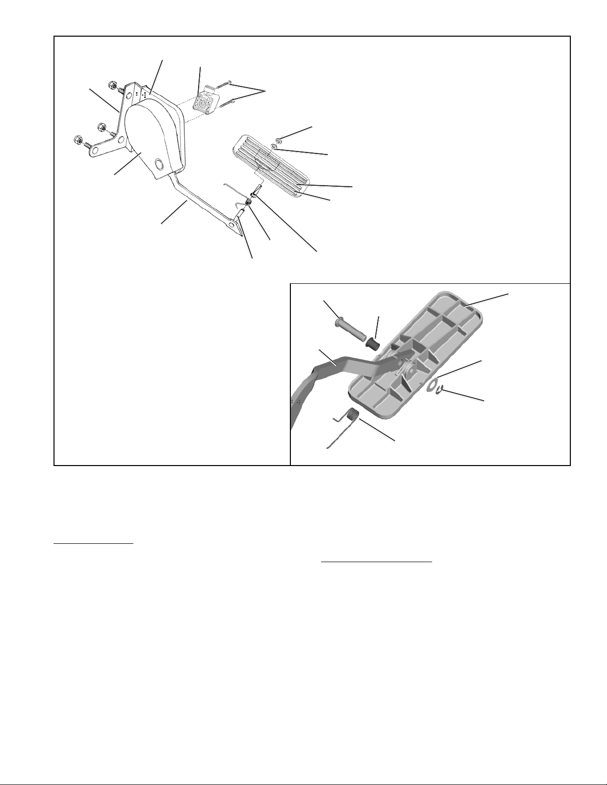
Bendix® ET- S™ & ET-S2™ Suspended Electronic Treadle
SD-15-4111
TREADLE
ACTUATOR BODY
MOUNTING
TREADLE
FIGURE 1 - ET-S
PLATE
CONNECTOR
POTENTIOMETER
ET-S™ TREADLE
™
AND ET-S2™ ELECTRONIC TREADLES
ACTUATOR BASE
MOUNTING
PLATE
DESCRIPTION
The ET-S™ and ET-S2™ treadles are engine compartment
bulkhead mounted electronic treadles. On electronically
controlled diesel engines, the electronic treadle fulfills the
same function as a conventional mechanical throttle.
However, rather than transmitting a mechanical force to the
engine governor, the electronic treadle controls engine speed
by supplying a variable electrical voltage to the engine’s
electronic controller.
The main components of the ET-S™ and ET-S2™ treadles
are: a mounting plate, suspended treadle, potentiometer
(variable resistor), actuator body and base. The selected
potentiometer, chosen for a specific engine application,
provides the electrical link to the engine control system.
OPERATION
The electronic treadles provide smooth, graduated throttle
control through the function of its potentiometer (variable
resistor). The drive shaft of the cam follower assembly
transfers any movement of the treadle to the potentiometer.
POTENTIOMETER
MOUNTING
PLATE
TREADLE PIVOT PIN
TREADLE
ET-S2™ TREADLE
DETROIT CATERPILLAR CUMMINS
DIESEL
CLOSED
THROTTLE 7 - 18% 10 - 20% 5 - 17%
IDLE (OPEN)
OPEN
THROTTLE 74 - 90% 75 - 90% 70 - 81%
(FULL)
FIGURE 2 - OUTPUT VOLTAGE, AS A PERCENTAGE OF
SUPPLY VOL TAGE
8V
CATERPILLAR
5V
™
ET-S
TREADLE
OUTPUT
VOLTAGE
○○○○○○○○○○○○○○○○○○○○○○
0V
CLOSED THROTTLE
(OPEN)
FIGURE 3 - OUTPUT VOL TAGE
CUMMINS
DETROIT
DIESEL
OPEN THROTTLE
(FULL)
MAX
RPM
ENGINE
IDLE
1
Page 2

As the potentiometer rotates, its resistance changes. This
way , the potentiometer can react to the driver’s request for
™
engine power through the ET-S
or ET-S2™ treadle by
changing resistance. The resulting change of voltage is
sensed by the electronic engine controller.
The electronic treadle receives its supply voltage from the
engine control unit. If the driver does not request engine
power, the treadle is in the idle position. This condition is
also referred to as “Closed Throttle.” In this state, the
potentiometer returns the minimum percentage of supply
voltage to the engine control unit (see Figure 2).
As the driver depresses the treadle, the electronic treadle
output voltage increases (see Figure 3). The potentiometer
allows an increased amount of its supply voltage to return to
the engine control unit, which in turn increases the engine’s
speed.
In the full, or “Open Throttle” position, the driver has
depressed the treadle to its furthest possible point. This is
the state of least potentiometer resistance. The electronic
treadle returns the maximum percentage of supply voltage
to the engine control unit (see Figure 2).
PREVENTIVE MAINTENANCE
Important: Review the warranty policy before performing
any intrusive maintenance procedures. An extended warranty
may be voided if intrusive maintenance is performed during
this period.
Because no two vehicles operate under identical conditions,
maintenance intervals will vary. Experience is a valuable guide
in determining the best maintenance interval for a vehicle.
GENERAL
Important: Visually check for physical damage to the
electronic treadle such as broken or missing parts. Actuate
the pedal five times from stop to stop, noting any binding or
soft pedal response.
Important Note: DO NOT DISASSEMBLE THE ACTUA TOR
BODY. Replace the ET-S™ or ET-S2™ treadle if there is
any binding, soft pedal actuation or if the nylon washers or
retaining rings indicated in Figure 4 are cracked or have
signs of deterioration.
CAM FOLLOWER
DRIVE SHAFT
POTENTIOMETER
MOUNTING PLATE
FIGURE 4 - TOP SECTIONAL VIEW
RETAINING
RINGS
NYLON
WASHERS
Perform the inspections presented at the prescribed interval.
If the electronic treadle fails to function as described, it should
be repaired or replaced with a new or genuine Bendix remanufactured unit, available at any authorized parts outlet.
Every 3 months, or 25,000 miles, or 900 operating hours:
1. Remove any accumulated contaminants and visually
inspect the exterior of the electronic treadle assembly
for physical damage or excessive corrosion.
2. Inspect electrical connections and cable assembly for
signs of corrosion, wear, or physical damage. Replace
as necessary.
3. Inspect treadle spring, sleeve bearing, nylon washer,
rubber treadle cover (ET-S™ treadle only) and retaining
ring for cracks or deterioration. Replace as necessary .
ET-S™ & ET-S2™ TREADLE REMOVAL
1. Park the vehicle on a level surface and block the wheels.
2. Drain the air pressure from all vehicle reservoirs.
3. Disconnect the cable assembly of the potentiometer.
Lift the lock tab and pull the connectors until they
disengage.
4. Remove the electronic treadle from the vehicle, set aside
the mounting hardware for reassembly.
DISASSEMBLY
Please note that the internal mechanism of the ET-S™ and
ET-S2™ treadle are not field-serviceable and therefore
individual parts or parts kits are not available for these
components. Disassembly may lead to malfunction of the
ET-S™ or ET-S2™ treadle.
The following instructions cover the maintenance and
replacement of the potentiometer and treadle (with its
bearing, spring etc.) only. The instructions provided with
those items should be followed in lieu of the steps presented
here. There are no other field-serviceable parts.
2
Page 3
MOUNTING
PLATE
ACTUATOR
BODY
ACTUATOR
BASE 1
TREADLE
ARM
ET-S™ TREADLE
POTENTIOMETER
PIVOT PIN
2
#10 SCREWS
7
SPRING
3
RETAINING
RING
4
NYLON
WASHER
REPLACEABLE
RUBBER
COVER
™
(ET-S
TREADLE
ONLY)
6
NYLINER
BEARING
TREADLE
5
PIVOT PIN
TREADLE
ARM
FIGURE 5 - ET-S™ AND ET-S2™ TREADLE EXPLODED LINE DRAWING
All other repairs require replacement of the ET-S™ or
ET-S2™ treadle.
Refer to Figure 5 throughout the procedures.
Remove the pivot pin from the treadle assembly. Gently
release the tension on the treadle spring (7) while removing
the treadle from the treadle arm. Remove the nyliner bearing (6) from the treadle arm.
Treadle Removal:
ET-S™ Treadle
Position the treadle on its side with the potentiometer facing up. Remove the small retaining ring (3) and small nylon
washer (4) that hold the treadle on to the treadle arm and
set aside for the assembly process. After the washer is
removed, pull the treadle off, carefully releasing the pressure from the treadle spring (7). Set the spring (7), nyliner
bearing (6) and the treadle aside for the reassembly process. Inspect rubber treadle cover - replace if necessary .
ET-S2™ Treadle
Position the treadle assembly on its side with the potentiometer facing down. Remove the small retaining ring (3)
and the nylon washer (4) from the treadle pivot pin.
Potentiometer Removal:
Secure the mounting plate. Important: Do not clamp the
assembly by the treadle actuator body or base since
overclamping may cause the casting to be distorted.
Remove the two screws (2) that secure the potentiometer
(1) to the actuator base. The potentiometer (1) can then be
lifted away from the drive shaft.
CLEANING AND INSPECTION
1. Use suitable solvent to clean all metal parts (note that
mineral spirits may damage the paint finish).
2. Inspect the treadle and mounting plate for severe
corrosion, pitting, or cracks. Replace as necessary.
Superficial corrosion and/or pitting is acceptable.
6
NYLINER
BEARING
SPRING
TREADLE
4
NYLON
WASHER
3
RETAINING
RING
7
ET-S2
™
TREADLE
3
Page 4

3. Inspect the cable assembly for loose or frayed wires,
physical damage, or any contaminants on the connectors. Replace as necessary .
ASSEMBLY
1. Securely clamp the treadle mounting plate.
2. (a) For Detroit Diesel Potentiometers: Align the drive
slot, and engage the potentiometer the drive tang at the
end of the drive shaft (see Figure 4). Rotate the
DIGITAL
VOLT/
OHM
METER
POWER
SUPPLY
(9-16 VDC)
300,000 OHM RESISTOR
TEST LOAD
potentiometer clockwise until the first set of mounting
holes align. Secure using two screws: torque to 25 (±5)
in. lbs.
(b) For Caterpillar Position Sensor: Aligning the drive
slot, the position sensor engages the drive tang at the
end of the drive shaft (see Figure 4). Rotate the position
sensor clockwise until the first set of mounting holes
align. Secure using two screws : torque to 20 (±2) in.
lbs.
POTENTIOMETER
PC. NO. ON THIS SURFACE
PIN C
GROUND
PIN B
VOUT
(OUTPUT)
PIN A
Closed Throttle (open) Range: 7-18%
Open Throttle (full) Range: 74-84%
FIGURE 6 - ELECTRICAL TEST SCHEMATIC FOR THE DETROIT DIESEL CONNECTOR
Closed Throttle (open) Range: 10-20%
Open Throttle (full) Range: 75-90%
PIN A VREF
(INPUT)
2000 OHM ±5%
RESISTOR
PEDAL
POSITION
SENSOR
(PWM)
.001µF
PIN B
VOUT
(OUTPUT)
47,000 OHM ±5%
RESISTOR
VREF
(INPUT)
POTENTIOMETER
(CABLE)
POSITION SENSOR
PIN C
GROUND
Caterpillar output voltage is Pulse Width Modulated
FIGURE 7 - ELECTRICAL TEST SCHEMA TIC FOR THE CATERPILLAR CONNECTOR
4
Page 5

IDLE
VALIDATION
SWITCH
PEDAL
POSITION
SENSOR
DIODES
IVS
PIN 6
PIN 2
PIN 1
PIN 5
PIN 3
PIN 4
TEST
LOAD
470
OHM
TEST LOAD
47000 OHM
TEST
LOAD
470
OHM
.01µF
Vs
SUPPLY
VOLTAGE
V3 (LOGIC HIGH AT IDLE)
V2 (LOGIC LOW AT IDLE)
IVS GROUND
Vs
SUPPLY
VOLTAGE
V1
(OUTPUT)
APS
GROUND
Closed Throttle (open) Range: 5-17%
Open Throttle (full) Range: 70-81%
LOCK TAB
5
VS
APS GROUND
3
V1
(OUTPUT) SIG1 2
(INPUT)4
IVS GROUND
(IVS) V 2
POTENTIOMETER
SET VOLTAGE
AND PC. NO.
SHOWN
HERE
6
(IVS)
V 3
LOCK TAB
1
FIGURE 8 - ELECTRICAL TEST SCHEMATIC FOR THE CUMMINS CONNECTOR
(c) For Cummins Potentiometers:
Test 1: Where the set resistance and voltage is
shown on a label. The Cummins potentiometer on
the ET-S™ and ET-S2™ treadle has an integral idle
validation switch. It also has a set resistance value
marked on the cover, which needs to be used to properly
install the potentiometer. The drive slot in the
potentiometer should engage with the drive tang at the
end of the drive shaft. Next rotate the potentiometer
until the hole in the metal sleeve matches the mounting
holes on the actuator base. Loosely screw the
potentiometer in place but do not tighten. Connect an
ohmmeter to pins 3 (APS output) and 4 (APS ground)
as shown in Figure 8. Now the installer should read the
set resistance value marked on the label. Rotate the
potentiometer until the ohmmeter reads the same
resistance as shown on the label within ±10 Ohms. Next,
while holding the potentiometer at the set resistance
screw and lock the potentiometer in place (torque to 25
inch pounds ±5). The sleeves lock into the body of the
potentiometer for easy removal and reassembly.
Test 2: Where the potentiometer has no label, but
has engraved set voltage shown. The Cummins
potentiometer on the electronic treadle has an integral
idle validation switch. It also has a set voltage value
marked on the cover, which needs to be used to properly
install the potentiometer. The drive slot in the
potentiometer should engage with the drive tang at the
end of the drive shaft. Next rotate the potentiometer
until the hole in the metal sleeve matches the mounting
holes on the actuator base. Loosely screw the
potentiometer in place but do not tighten. Construct the
test circuit following the circuit diagram shown in Figure
8. T o make the test circuit connect the test load resistor
(47,000 Ohms) and a capacitor (.01 MicroFarads) across
pins 3 and 4 of the potentiometer. Then connect a
voltmeter to the lead ends of the test circuit. Next connect
a 5 volt power supply to the potentiometer at pin 4 (APS
ground) and pin 5 (supply voltage). Caution: Sensor
may be damaged if supply exceeds 5 volts. Now the
installer should read the set voltage value marked on
the potentiometer. Rotate the potentiometer until the
voltmeter reads the same voltage as shown on the
potentiometer within ±.02 volts. Next screw and lock
the potentiometer in place (torque to 25 inch pounds
±5). The sleeves lock into the body of the potentiometer
for easy removal and reassembly .
T est 3: Perform the following Operational Te st before
installing the electronic treadle:
OPERA TIONAL TEST
[Note for Cummins potentiometers only: The optimum
output & switch points should be achieved when the idle
voltage equals the set voltage or set resistance written on
the potentiometer. Use the test circuit shown in Figure 8.]
a. Check that the electronic treadle mounting plate is
securely attached to a smooth, flat surface in such a
way that does not twist the unit.
5
Page 6

b. Connect the potentiometer or position sensor to the volt
meter and power supply as shown in Figures 6, 7 or 8,
depending on the model. Note: The power supply needs
to be 5 VDC. Do not exceed this voltage.
c. Verify that the closed throttle (idle) output voltage, as a
percentage of supply voltage, is within the limits listed
in Figure 2. For example, with a supply voltage of 5
volts, for the Caterpillar potentiometer in its closed throttle
position, read between 0.5 to 1.0 volts (10%-20% of
supplied voltage).
d. Depress the treadle to its full throttle position. The output
voltage, as a percentage of supply voltage, should be
within the limits listed in Figure 2. For example, with a
supply voltage of 5 volts, for the Caterpillar position
sensor in its open throttle position, read between 3.75
to 4.5 volts (75-90% of supplied voltage).
e. Make five full applications and record idle position voltage
each time. Verify that idle position volt ages recorded do
not vary by more than .4% (For example, for a 5 volt
supply , if there is any variation, the difference between
the high and low readings should not exceed .02 volts).
If the electronic treadle fails to function within its specified
ranges, it should be repaired or replaced with a new or
genuine Bendix remanufactured unit, available at any
authorized parts outlet.
Treadle Installation:
ET-S™ Treadle
1. Replace the rubber treadle cover if needed.
2. Place the spring (7) on the treadle pivot pin.
3. Install the nyliner bearing (6) into the treadle. Note: the
nyliner bearing collar is placed on the treadle arm side.
Holding the spring in position, the treadle is then installed. The nylon washer (4) and retaining ring (3) secure
the treadle into position.
4. Make sure the ET-S™ treadle has a smooth, even treadle
movement.
5. Install the ET-S™ treadle on the vehicle (see ET-S™ &
ET-S2™ T readle Installation).
ET-S2™ Treadle
1. Position the treadle assembly on its side with the potentiometer facing up.
2. Insert the nyliner bearing (6) into the treadle arm with the
collar up (toward potentiometer side). The nyliner bearing (6) will protrude through the treadle arm providing a
guide for the treadle spring (7).
3. Place the treadle spring (7) on the protruding portion of the
nyliner bearing with the tangs of the treadle spring (7) pointing toward the ET-S2™ treadle body. The short tang should
rest on the top side of the treadle arm. Align the treadle
arm and treadle spring with the recess in the underside of
the treadle.
4. Insert the pivot pin from the potentiometer side of the
ET-S2™ treadle assembly through the treadle, treadle
arm, nyliner bearing (6) and spring (7). Secure with the
nylon washer (4) and retaining ring (3).
5. Make sure the ET-S2™ treadle has smooth, even treadle
movement.
6. Install the ET -S2™ treadle on the vehicle (see ET-S™ &
ET-S2™ T readle Installation).
ET-S™ & ET-S2™ TREADLE INSTALLATION
1. Using the mounting hardware set aside, install the
assembled electronic treadle on the vehicle. Torque to
between 85 and 1 10 lb. in.
2. Reconnect the cable connector by plugging it into the
potentiometer’s integral connector and pushing until the
lock tab snaps into place.
WARNING! PLEASE READ AND FOLLOW
THESE INSTRUCTIONS TO AVOID
PERSONAL INJURY OR DEATH:
When working on or around a vehicle, the following
general precautions should be observed at all times.
1. Park the vehicle on a level surface, apply the
parking brakes, and always block the wheels.
Always wear safety glasses.
2. Stop the engine and remove ignition key when
working under or around the vehicle. When
working in the engine compartment, the engine
should be shut off and the ignition key should be
removed. Where circumstances require that the
engine be in operation, EXTREME CAUTION should
be used to prevent personal injury resulting from
contact with moving, rotating, leaking, heated or
electrically charged components.
3. Do not attempt to install, remove, disassemble or
assemble a component until you have read and
thoroughly understand the recommended
procedures. Use only the proper tools and observe
all precautions pertaining to use of those tools.
4. If the work is being performed on the vehicle’s air
brake system, or any auxiliary pressurized air
systems, make certain to drain the air pressure from
all reservoirs before beginning ANY work on the
vehicle. If the vehicle is equipped with an AD-IS
air dryer system or a dryer reservoir module, be
sure to drain the purge reservoir.
5. Following the vehicle manufacturer’s
recommended procedures, deactivate the electrical
system in a manner that safely removes all
electrical power from the vehicle.
6. Never exceed manufacturer’s recommended
pressures.
7. Never connect or disconnect a hose or line
containing pressure; it may whip. Never remove a
component or plug unless you are certain all
system pressure has been depleted.
™
6
Page 7

8. Use only genuine Bendix® replacement parts,
components and kits. Replacement hardware,
tubing, hose, fittings, etc. must be of equivalent
size, type and strength as original equipment and
be designed specifically for such applications and
systems.
9. Components with stripped threads or damaged
parts should be replaced rather than repaired. Do
not attempt repairs requiring machining or welding
unless specifically stated and approved by the
vehicle and component manufacturer.
10. Prior to returning the vehicle to service, make
certain all components and systems are restored
to their proper operating condition.
7
Page 8

8
BW1837 © 2004 Bendix Commercial Vehicle Systems LLC. All rights reserved. 6/2004 Printed in U.S.A.
 Loading...