

Page 1
®
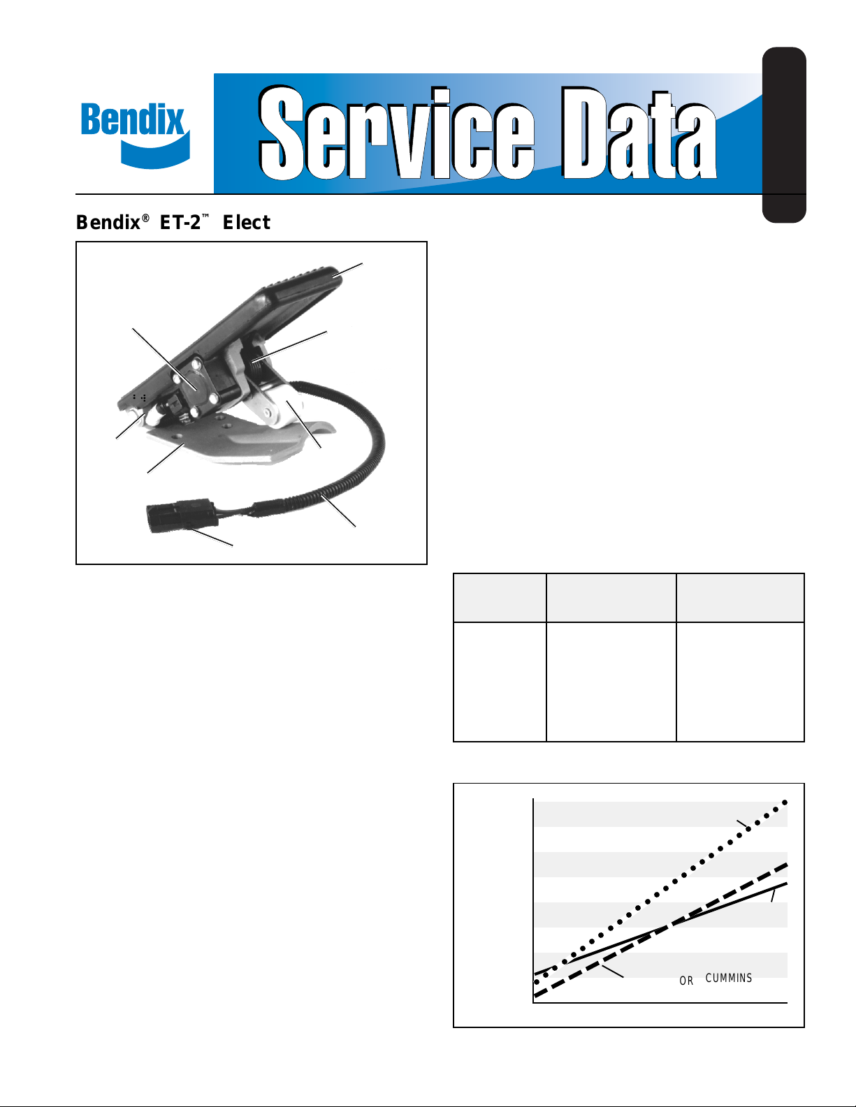
Bendix® ET-2™ Electronic Treadle
SD-15-4106
TREADLE
COVER
POTENTIOMETER
PIVOT SPRING
MOUNTING BASE
CONNECTOR
FIGURE 1 - ET-2™ ELECTRONIC TREADLE
DOUBLE RETURN
SPRING
ROLLER
CABLE ASSEMBLY
DESCRIPTION
The ET-2™ is an electronic throttle. On electronically
controlled diesel engines, the ET-2™ treadle fulfills the same
function as a conventional mechanical throttle. The ET -2
treadle controls engine speed by interacting with an
electronic fuel management controller on the engine, rather
than transmitting a mechanical force from the throttle pedal
to the engine governor.
The main components of the ET-2™ throttle are a cast
aluminum mounting base and treadle, a rubber treadle cover,
a potentiometer (variable resistor), and a roller assembly.
The potentiometer is specific to each engine application.
OPERATION
The ET-2™ treadle provides smooth, graduated throttle control
through the function of its variable resistor , or potentiometer.
The ET-2™ treadle receives its supply voltage from the engine
control unit. The lever shaft connects the roller assembly
to the potentiometer, so that any movement of the treadle
rotates the potentiometer. As the potentiometer rotates,
its resistance changes. This way, the potentiometer
communicates the throttle position to the fuel control
system by changing resistance, returning more or less of
the supplied voltage back to the electronic engine controller.
If the driver does not request engine power, the throttle is in
the idle (or “closed throttle”) position. In this state, the
potentiometer significantly reduces the amount of supply
voltage returned to the engine control unit (See Figure 2).
As the driver depresses the ET-2™ treadle, output voltage
increases (see Figure 3). The potentiometer allows an
increased amount of its supply voltage to return to the engine
control unit, which in turn increases the engine’s speed.
In the full (or “open throttle”) position, the driver has fully
depressed the ET-2™ treadle. This is the state of least
potentiometer resistance. The ET-2™ treadle returns the
maximum percentage of supply voltage to the engine control
unit (see Figure 2).
Engine Idle Throttle Full Throttle
Manufacturer (Closed) (Open)
CAT 13 - 21% 79 - 89%
™
Cummins 8 - 18% 70 - 80%
Detroit Diesel 6 - 14% 86 - 94%
Mack 10 - 20% 70 - 85%
FIGURE 2 - ET-2™ TREADLE OUTPUT VOLTAGE, AS A
PERCENTAGE OF SUPPLY VOL TAGE
8V
7
6
™
ET-2
TREADLE
OUTPUT
VOLTAGE
FIGURE 3 - ET-2
5
4
3
2
1
0V
CLOSED THROTTLE OPEN THROTTLE
○○○○○○○○○○○○○○○○○○○○○○○○○○○○
™
TREADLE OUTPUT VOL TAGE
DETROIT
DIESEL
OR
CAT
CUMMINS
MACK
1
Page 2
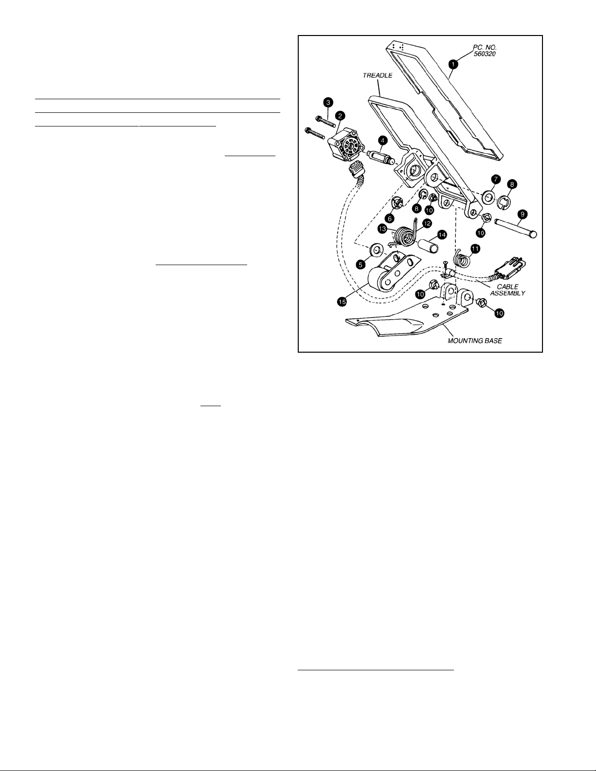
Figure 3 illustrates the relationship between throttle position
and engine RPM. Potentiometer performance will vary for
each engine application, therefore potentiometers must not
be interchanged.
WARNING! PLEASE READ AND FOLLOW
THESE INSTRUCTIONS TO AVOID
PERSONAL INJURY OR DEATH:
When working on or around a vehicle, the following
general precautions should be observed at all times.
1. Park the vehicle on a level surface, apply the
parking brakes, and always block the wheels.
Always wear safety glasses.
2. Stop the engine and remove ignition key when
working under or around the vehicle. When
working in the engine compartment, the engine
should be shut off and the ignition key should be
removed. Where circumstances require that the
engine be in operation, EXTREME CAUTION should
be used to prevent personal injury resulting from
contact with moving, rotating, leaking, heated or
electrically charged components.
3. Do not attempt to install, remove, disassemble or
assemble a component until you have read and
thoroughly understand the recommended
procedures. Use only the proper tools and observe
all precautions pertaining to use of those tools.
4. If the work is being performed on the vehicle’s air
brake system, or any auxiliary pressurized air
systems, make certain to drain the air pressure from
all reservoirs before beginning ANY work on the
vehicle. If the vehicle is equipped with an AD-IS
air dryer system or a dryer reservoir module, be
sure to drain the purge reservoir.
5. Following the vehicle manufacturer’s
recommended procedures, deactivate the electrical
system in a manner that safely removes all
electrical power from the vehicle.
6. Never exceed manufacturer’s recommended
pressures.
7. Never connect or disconnect a hose or line
containing pressure; it may whip. Never remove a
component or plug unless you are certain all
system pressure has been depleted.
8. Use only genuine Bendix® replacement parts,
components and kits. Replacement hardware,
tubing, hose, fittings, etc. must be of equivalent
size, type and strength as original equipment and
be designed specifically for such applications and
systems.
9. Components with stripped threads or damaged
parts should be replaced rather than repaired. Do
not attempt repairs requiring machining or welding
unless specifically stated and approved by the
vehicle and component manufacturer.
10. Prior to returning the vehicle to service, make
certain all components and systems are restored
to their proper operating condition.
FIGURE 4 - EXPLODED VIEW
PREVENTIVE MAINTENANCE
GENERAL
™
Perform the following tests and inspections at the prescribed
intervals. If the ET-2™ treadle does not function as described,
repair it or replace it with a new unit, available at any
authorized Bendix parts outlet. EVERY 3 MONTHS, 25,000
MILES, OR 900 OPERA TING HOURS:
1. Remove any accumulated contaminants and visually
inspect the exterior of the ET-2™ treadle for physical
damage or excessive corrosion.
2. Inspect electrical connections and cable assembly for
signs of corrosion, wear, or physical damage. Replace
as necessary.
3. Inspect springs (11, 12, 13) for signs of corrosion or
pitting. Replace as necessary.
4. Inspect bearings (10), washer (7), and snap rings (8)
for cracks or deterioration. Replace as necessary.
OPERATIONAL TEST
Perform these tests only if the vehicle’s throttle does not
appear to operate as expected.
Test 1: For Mack and DDC engines:
1. Unplug the cable assembly from the potentiometer’s
integral connector by lifting the lock tab and pulling
the connectors until they disengage. Inspect cable
assembly for loose terminals, frayed wires, corrosion,
2
Page 3
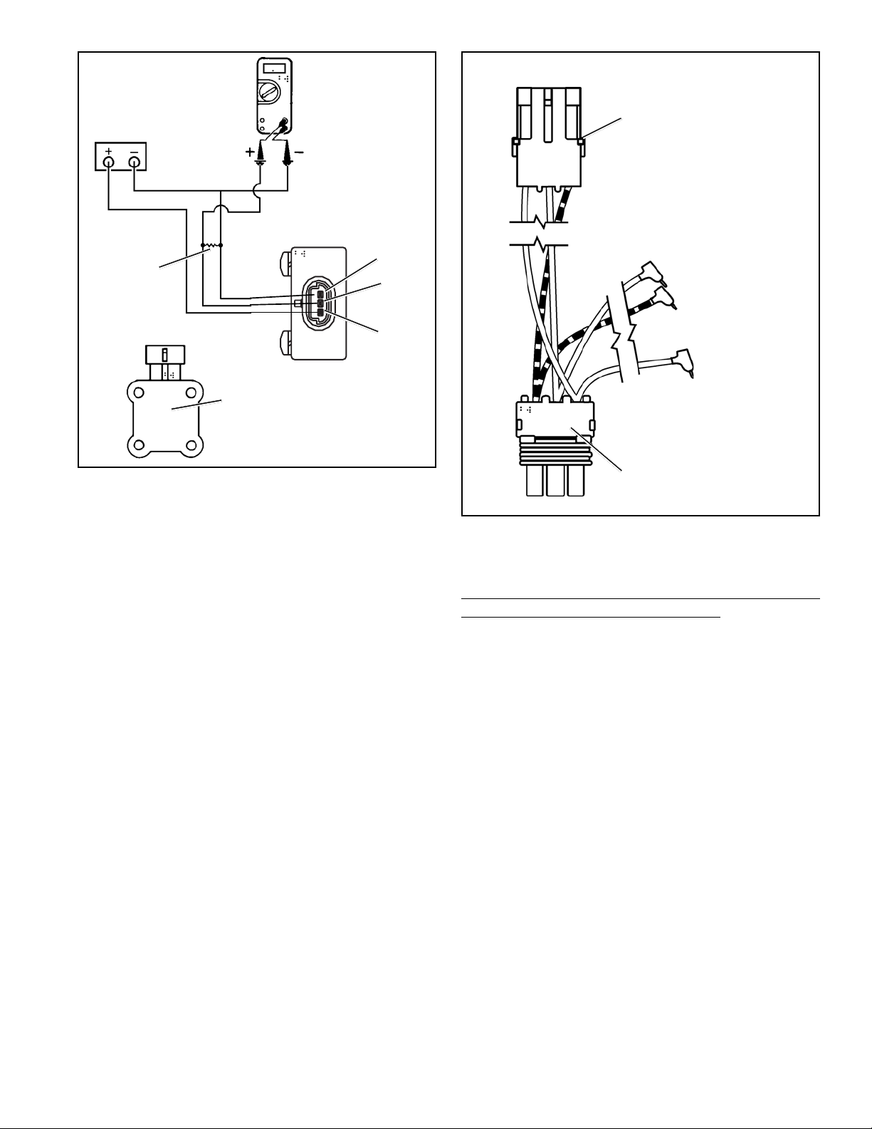
POWER
SUPPLY
(9-16 VDC)
DIGITAL
VOLT/
OHM
METER
A B C
PACKARD ELECTRIC
CONNECTOR 12010717
(CONNECTOR X)
PIN C
RESISTOR
TEST LOAD
(47,000 OHM FOR
DETROIT DIESEL,
300,000 OHM
FOR MACK)
POTENTIOMETER
POTENTIOMETER
PC. NO. ON THIS
SURFACE
FIGURE 5 - ET-2™ TREADLE ELECTRICAL TEST
SCHEMATIC FOR THE DETROIT DIESEL CONNECTOR
GROUND
PIN B
VOUT
(OUTPUT)
PIN A
VREF
(INPUT)
wear, or physical damage. Check end-to-end electrical
continuity at terminals. NOTE: Potentiometer pin
locations will remain constant (see Figure 5). However,
cable assembly connector pin out may vary from engine
to engine.
2. Remove the ET-2™ treadle from the vehicle.
3. Secure the ET-2™ treadle to a smooth, flat surface in
such a way that it does not twist the unit.
4. Connect the potentiometer to the volt meter and power
supply as shown in Figure 5. NOTE: Power supply
can be a 12 VDC vehicle battery in good condition and
with known voltage output.
5. Verify that the closed throttle (idle) output voltage, as
a percentage of supply voltage, is within the limits listed
in Figure 2.
6. Depress the treadle to its full throttle position. The
output voltage, as a percentage of supply voltage,
should be within the limits listed in Figure 2, e.g.
Testing a Detroit Diesel ET -2™ Treadle Potentiometer:
Battery = 10 VDC. Full throttle = 9 VDC. 9/10 x 100 =
90%.
7. Make several full applications and record idle position
voltage each time. Verify that idle position voltage does
not vary by more than .4% (.02 volts). If the ET-2
treadle does not operate within its specified ranges,
service the unit, or replace it with a new ET-2™ treadle,
available at your nearest Bendix parts outlet.
INPUT PIN 3
OUTPUT PIN 2
GROUND PIN 1
PACKARD ELECTRIC
CONNECTOR 12015793
C B A
FIGURE 6 - ET-2
SCHEMATIC FOR THE CUMMINS CONNECTOR
™
TREADLE ELECTRICAL TEST
(CONNECTOR Y)
Test 2: For Cummins engines (featuring a separate
potentiometer and idle validation switch):
T o test the potentiometer on the vehicle, use steps 1 through
8. Alternatively, instructions for carrying out a “bench test”
is covered in instructions 1 1 through 16.
1. First construct the “breakout” harness shown in Figure 6.
2. Insert connector X on the breakout harness into the
connector leading from the potentiometer. Then insert
connector Y on the breakout harness into the connector
leading from the dashboard wire harness.
3. Next insert pin 1 into the ground position on a voltmeter.
Then insert pin 2 into the positive position on a volt
meter.
4. Disconnect the idle validation switch cable from the
dashboard wire harness. Connect an ohmmeter to pins
A and B on the connector leading from the idle
validation switch. The positive lead should be
connected to pin A and the negative lead should be
connected to pin B.
5. Turn the vehicle’s ignition key to the “battery on”
™
position. This supplies a 5 volt input to the
potentiometer. Since the idle validation switch is no
longer connected, a fault code may be triggered on
some vehicles. This fault code will be reset at the end
of this test.
3
Page 4

6. Record the output voltage when the pedal is in the idle
position (V1). Then slowly depress the pedal. When
the ohm meter shows that the resistance has changed
from “overload” to about .003 ohms (or from .003 ohms
to “overload”), stop depressing the pedal. Record the
voltage (Vx) registered with the pedal in this position.
Then press the pedal to the full throttle position and
record the output voltage (V2).
7. Calculate the “switch point percentage” using the formula
below.
Switch point percentage = ((Vx-V1)/(V2-V1))*100
Vx = Output voltage when the switch changed
V1 = idle voltage
V2 = full throttle voltage
DIGITAL
POWER
SUPPLY
(9-16 VDC)
RESISTOR
TEST LOAD
47,000 OHM
FIGURE 7 - ET-2
SCHEMATIC FOR THE CUMMINS CONNECTOR
VOLT/
OHM
METER
POTENTIOMETER
POTENTIOMETER
PC. NO. ON THIS
SURFACE
™
TREADLE ELECTRICAL TEST
PIN C
GROUND
PIN B
VOUT
(OUTPUT)
PIN A
VREF
(INPUT)
8. The switch point percentage should be between 3% to
10%. If it is not with in this range adjust the
potentiometer by loosening the mounting screws and
turning the potentiometer within the range allowed by
the mounting holes. Repeat steps 1-7 again. If you can
not obtain the proper switch point percentage, replace
with a new ET-2™ treadle, available at your nearest
Bendix parts outlet.
9. After a successful test the vehicle may be returned to
service.
The following instructions are for a bench test for the
potentiometer used with Cummins engines.
10. Unplug the cable assembly from the potentiometer’s
integral connector by lifting the lock tab and pulling the
connectors until they disengage. Inspect cable
assembly for loose terminals, frayed wires, corrosion,
wear, or physical damage. Check end-to-end electrical
continuity at terminals. NOTE: Potentiometer pin
locations will remain constant (see Figure 5). However,
cable assembly connector pin out may vary from engine
to engine.
1 1. Remove the ET-2™ treadle from the vehicle.
12. Secure the ET-2™ treadle to a smooth, flat surface in
such a way that it does not twist the unit.
13. Connect the potentiometer to the volt meter and power
supply as shown in Figure 5. NOTE: Power supply
can be a 12 VDC vehicle battery in good condition and
with known voltage output.
14. V erify that the closed throttle (idle) output voltage, as a
percentage of supply voltage, is within the limits listed
in Figure 2.
15. Depress the treadle to its full throttle position. The
output voltage, as a percentage of supply voltage, should
be within the limits listed in Figure 2. e.g. Testing a
Detroit Diesel ET-2™ Treadle Potentiometer: Battery =
10 VDC. Full throttle = 9 VDC. 9/10 x 100 = 90%.
16. Make several full applications and record idle position
voltage each time. Verify that idle position volt age does
not vary by more than .4% (.02 volts). If the ET-2
treadle does not operate within its specified ranges,
service the unit, or replace it with a new ET-2™ treadle,
available at your nearest Bendix parts outlet.
Test 3: For Cummins engines (with integrated switch
and sensor (ISS): For use only with the Cummins Celet
Plus and later editions of the ECU. This sensor can
not be used to replace the separate potentiometer &
idle validation switch. To do this a new ET-2™ treadle
with the ISS must be purchased.
Test 1: Where the set resistance and voltage is shown
on a label. The Cummins potentiometer on the ET-2
treadle has an integral idle validation switch. It also has a
set resistance value marked on the cover , which needs to
be used to properly install the potentiometer. The drive
slot in the potentiometer should engage with the drive
tang at the end of the drive shaft. Next rotate the
potentiometer until the hole in the metal sleeve matches
the mounting holes on the actuator base. Loosely screw
the potentiometer in place but do not tighten. Connect
an ohmmeter to pins 3 (APS output) and 4 (APS ground)
as shown in Figure 8. Now the installer should read the
set resistance value marked on the label. Rotate the
™
™
4
Page 5

Closed Throttle (open) Range: 10-20%
Open Throttle (full) Range: 75-90%
PIN A VREF
(INPUT)
-8V
2000 OHM ±5%
RESISTOR
PEDAL
POSITION
SENSOR
(PWM)
.001µF
FIGURE 8 - ET-S™ TREADLE ELECTRICAL TEST SCHEMA TIC FOR THE CATERPILLAR CONNECTOR
potentiometer until the ohmmeter reads the same
resistance as shown on the label within ±10 Ohms. Next,
while holding the potentiometer at the set resistance
screw and lock the potentiometer in place (torque to 25
inch pounds ±5). The sleeves lock into the body of the
potentiometer for easy removal and reassembly.
Test 2: Where the potentiometer has no label, but
has engraved set voltage shown. The Cummins
potentiometer on the ET-2™ treadle has an integral idle
validation switch. It also has a set voltage value marked
on the cover, which needs to be used to properly install
the potentiometer. The drive slot in the potentiometer should
engage with the drive tang at the end of the drive shaft.
Next rotate the potentiometer until the hole in the metal
sleeve matches the mounting holes on the actuator base.
Loosely screw the potentiometer in place but do not
tighten. Construct the test circuit following the circuit
diagram shown in Figure 8. To make the test circuit
connect the test load resistor (47,000 Ohms) and a
capacitor (.01 Microfarads) across pins 3 and 4 of the
potentiometer. Then connect a voltmeter to the lead ends
of the test circuit. Next connect a 5 volt power supply to
the potentiometer at pin 4 (APS ground) and pin 5 (supply
voltage). Caution: Sensor may be damaged if supply
exceeds 5 volts. Now the installer should read the set
voltage value marked on the potentiometer. Rotate the
potentiometer until the voltmeter reads the same voltage
as shown on the potentiometer within ±.02 volts. Next
PIN B
VOUT
(OUTPUT)
RED
47,000 OHM ±5%
RESISTOR
PIN C
GROUND
BLACK
Caterpillar output voltage is Pulse Width Modulated
VOLTMETER (V => %)
screw and lock the potentiometer in place (torque to 25
inch pounds ±5). The sleeves lock into the body of the
potentiometer for easy removal and reassembly .
Test 4: For CA T engines:
1. Securely clamp the treadle Mounting Plate (6).
2. For Caterpillar Potentiometers: Aligning the drive slot,
the Potentiometer (1) engages the drive tang at the end
of the Cam Follower Drive Shaft (see Figure 4). Rotate
the Potentiometer clockwise until the first set of
mounting holes align. Secure using two screws (2):
torque to 20 (±2) in. lbs.
To test the Caterpillar sensor construct the test circuit
shown in Figure 7. Connect both pin B and pin C into
a voltmeter. Set the voltmeter to the settings described
in Figure 7. Record the output values in Figure 2. If
the unit does not operate within the specified ranges,
service the unit or replace it with a new ET-2™ treadle.
REMOVAL
1. Park the vehicle on a level surface and block the wheels
and/or hold the vehicle by means other than the air
brakes.
2. Drain the air pressure from all vehicle reservoirs.
3. Unplug the cable assembly at the opposite end of the
potentiometer. Disconnect by lifting the lock tab and
pulling the connectors until they disengage.
4. Remove the ET-2™ treadle from the vehicle.
(CABLE)
POTENTIOMETER
5
Page 6

DIODES
TEST
LOAD
470
PIN 6
IDLE
VALIDATION
SWITCH
PEDAL
POSITION
SENSOR
FIGURE 8 - ET-2™ TREADLE ELECTRICAL TEST SCHEMATIC FOR THE CUMMINS CONNECTOR
IVS
PIN 2
PIN 1
PIN 4
OHM
PIN 5
PIN 3
TEST LOAD
47000 OHM
TEST
LOAD
470
OHM
.01µF
Vs
SUPPLY
VOLTAGE
V3 (LOGIC HIGH AT IDLE)
V2 (LOGIC LOW AT IDLE)
IVS GROUND
Vs
SUPPLY
VOLTAGE
V1
(OUTPUT)
APS
GROUND
Closed Throttle (open) Range: 5-17%
Open Throttle (full) Range: 70-81%
LOCK TAB
5
VS
4
APS GROUND
3
V1
(OUTPUT) SIG1
(INPUT)
2
(IVS) V 2
POTENTIOMETER
SET VOLTAGE
AND PC. NO.
SHOWN
HERE
6
(IVS)
V 3
LOCK TAB
1
IVS GROUND
INSTALLATION
1. Install the assembled ET-2™ treadle on the vehicle.
2. Reconnect the cable connector by plugging it into the
potentiometer’s integral connector and pushing until
the lock tab snaps into place.
DISASSEMBLY
The following instructions present a major disassembly of
the ET-2™ treadle. They are included for reference only.
Several replacement parts and maintenance kits that do
not require full disassembly are available. The instructions
provided with those items should be followed in lieu of the
steps presented here. Refer to Figure 4 throughout the
procedures.
1. Remove the treadle cover (1).
2. Remove the pivot pin’s snap ring (8).
3. Remove the pivot pin (9) and the two nyliner bearings
(10) from the treadle’s exterior. Also remove the two
nyliner bearings (10) from the mounting base.
4. Remove the pivot spring (11).
5. Remove the screws (3) that secure the potentiometer
(2) to the treadle. Remove the potentiometer.
6. Remove the lever shaft’s snap ring (5).
7. Remove the lever shaft (4) and the washer (7). Then
remove the roller assembly (15), the inner washer (5),
and the nyliner bearing (6) from the treadle. Separate
the treadle from the mounting base.
6
8. The roller assembly consists of the lever, roller, two
springs (12 & 13), and a spring support (14). Remove
the springs and the spring support from the lever.
CLEANING & INSPECTION
1. Use mineral spirits or an equivalent solvent to clean all
metal parts. Be sure to thoroughly dry the parts.
2. Inspect the treadle and mounting base for severe
corrosion, pitting, or cracks. Replace as necessary.
Superficial corrosion and/or pitting is acceptable.
3. Inspect the cable assembly for loose or frayed wires,
physical damage, or any contaminants on the
connectors. Check end-tend electrical continuity at
terminals. Replace as necessary.
ASSEMBLY
Refer to Figure 4 throughout the assembly procedure.
1. Install the four nyliner bearings (10) on the mounting
base and treadle.
2. Place the treadle “ears” outside the mounting base
“ears” so that the holes line up.
3. Install the pivot spring (11) into the base and treadle.
The curved end of the spring fits into a small hole in the
treadle, and the straight end fits into a small hole in the
mounting base.
4. The pivot pin (9) should slide through the holes in the
“ears” of the treadle and base assembly, then through
the center of the spring. Secure the pin with its snap
ring (8). Make sure the pivot spring is straight and is
seated in its holes.
Page 7

5. The installation of the remaining components is much
easier if the inner and outer springs (12 & 13) are
compressed and caged. This can be done with a short
piece of wire, or even a paper clip. The springs should
be compressed so that their ends are approximately
one inch apart.
6. Place the spring support (14) inside the caged spring
assembly. Then insert the springs into the roller
assembly (15). The curved ends of the springs fit over
the small bar directly behind the roller.
7. In order to install the lever shaft (4), the roller assembly,
with its springs and spring support, and the washers
(5 & 7) must be aligned. This can be done by resting
™
the ET-2
treadle on its side, with the smaller ear of the
treadle facing up. Insert the washers as shown in Figure
4. Washer (5) has the larger diameter (.520"). While
holding the roller assembly in place, push the lever shaft
through the treadle ears.
8. With the ET-2
™
treadle on its side, as mentioned above,
the lever shaft should protrude from the treadle with its
snap ring groove visible. Secure the lever shaft with its
snap ring (8).
9. Turn the ET-2™ treadle upright. Place the potentiometer
(2) in the position shown in Figure 4, with its connector
facing the rear of ET-2™ treadle. Secure the
potentiometer with its screws (3). Torque to 20 inch
pounds (+/-5).
10. Install the treadle cover (1) and cable assembly as shown
in Figure 4. Clip the wire from the spring assembly so
that the straight end of the springs rest against the
underside of the treadle.
1 1. Make sure the ET-2™ treadle has smooth, even treadle
movement. Also, perform Operational Test steps 3-7
™
before installing the ET -2
12.Install the ET-2
™
treadle on the vehicle.
treadle.
7
Page 8

8
BW1650 © 2004 Bendix Commercial Vehicle Systems LLC All rights reserved. 6/2004 Printed in U.S.A.
 Loading...