

Page 1
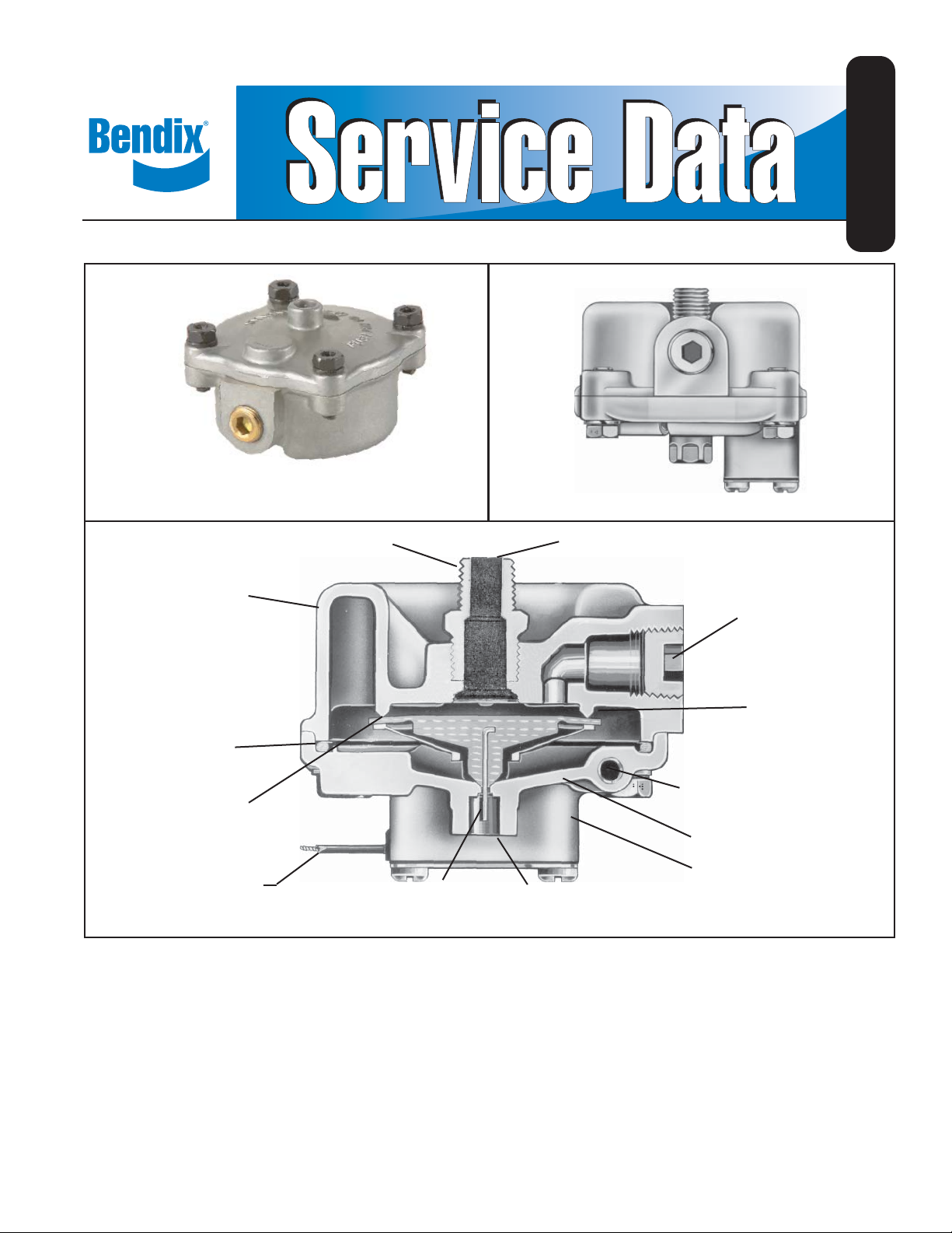
Bendix® DV-2™ Automatic Reservoir Drain Valve
SD-03-2501
STANDARD BENDIX
BODY
SEALING
RING
VALVE
GUIDE
ELECTRICAL
LEAD WIRE
DV-2™ VALVE
®
ADAPTER
BENDIX
BENDIX® DV-2™ VALVE
WITH HEATER
TOP
RESERVOIR
PORT
WIRE STEM
®
DV-2™ VALVE WITH HEATER AND THERMOSTAT
EXHAUST PORT
SIDE
RESERVOIR
PORT
INLET &
EXHAUST
VALVE
HEATER ELEMENT
COVER
THERMOSTAT
HOUSING
DESCRIPTION
The Bendix® DV-2™ automatic reservoir drain valve ejects moisture and
contaminants from the reservoir in which it is connected. It operates
automatically and requires no manual assistance or control lines from
other sources.
The automatic reservoir drain valve has a die cast aluminum body and
cover and is normally mounted either in the bottom of the reservoir using
the top port of the drain valve or in the end of an end drain reservoir
using the side port of the valve.
The DV-2™ valve is also available with a heater and thermostat cast
into the cover for vehicles operated in subfreezing temperatures. The
heated DV-2™ valve is supplied in either a 12 or 24 volt model and in
bottom or end drain confi guration. A 1/4” male pipe adapter is supplied
with all DV-2™ drain valves, end drain and bottom drain, both standard
and heated. This adapter should be installed directly into the reservoir.
Early versions included a fi lter screen in the adapter. The fi lter should
be discarded. Later versions may have a standard pipe nipple instead
of the adapter.
1
Page 2
NOTE: If a vehicle equipped with a Bendix® DV-2™ automatic drain
valve(s) is operated in subfreezing temperatures, it is
recommended that a heated reservoir drain valve is installed.
OPERATION
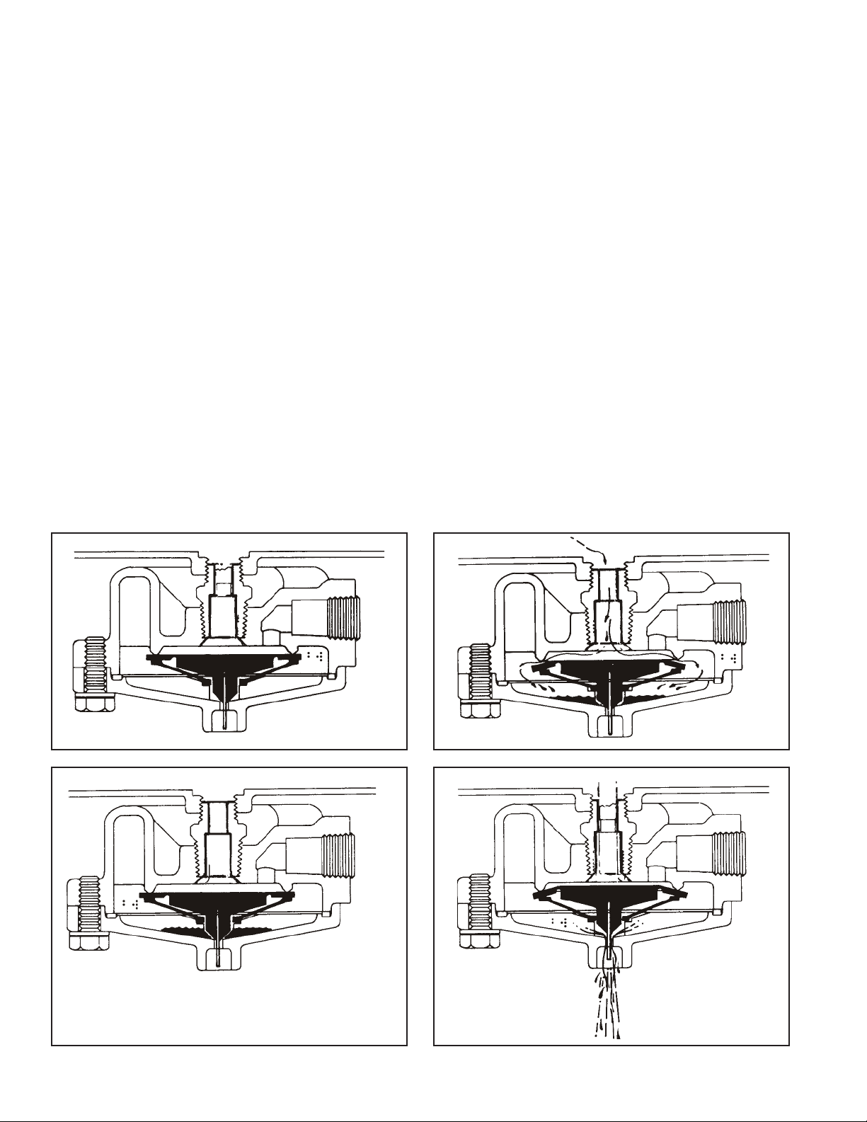
Referring to Figure 1, with no air pressure in the system, the inlet and
exhaust valves are closed. Upon charging the system, a slight pressure
opens the inlet valve (Figure 2) which permits air and contaminants to
collect in the sump. The inlet valve remains open when pressure is
ascending in the system until maximum (governor cutout) pressure
is reached. The spring action of the valve guide in the sump cavity
closes the inlet valve. The inlet valve and the exhaust valve are now
closed (Figure 3).
When reservoir pressure drops slightly (approximately 2 psi), air
pressure in the sump cavity opens the exhaust valve (Figure 4) and
allows moisture and contaminants to be ejected from the sump cavity
until pressure in the sump cavity drops suffi ciently to close the exhaust
valve.
The length of time the exhaust valve remains open and the amount of
moisture and contaminants ejected depends upon the sump pressure
and the reservoir pressure drop that occurs each time air is used from
the system.
Manual draining can be accomplished as follows:
Using a tool, move the wire in the exhaust port upward, holding it in
until draining is completed.
The thermostat on the heated model DV-2
™
automatic drain valve will
activate the heating element when the valve body reaches a temperature
of approximately 45°F and will deactivate the heating element when
the valve body is warmed to approximately 85°F.
PREVENTIVE MAINTENANCE
Important: Review the Bendix Warranty Policy before performing any
intrusive maintenance procedures. A warranty may be voided if intrusive
maintenance is performed during the warranty period.
No two vehicles operate under identical conditions, as a result,
maintenance intervals may vary. Experience is a valuable guide
in determining the best maintenance interval for air brake system
components. At a minimum, the automatic reservoir drain valve should
be inspected every 6 months or 1500 operating hours, whichever comes
fi rst, for proper operation. Should the automatic reservoir drain valve
not meet the elements of the operational tests noted in this document,
further investigation and service of the valve may be required.
Upon investigation, parts showing signs of wear or deterioration should
be replaced.
If there is a fi lter screen in the adapter fi tting it should be removed and
discarded.
FIGURE 1 FIGURE 2
FIGURE 3 FIGURE 4
2
Page 3

SERVICE CHECKS
IMPORTANT
OPERATING TEST
With system charged, make several foot valve applications and note
each time an application is made, an exhaust of air occurs at the exhaust
port of the drain valve. If no air comes out, push the wire stem. If no air
comes out, there may be a plugged fi lter in the adapter which should
be removed and discarded.
LEAKAGE TEST
With system charged and pressure stabilized in system, there should
be no leaks at the drain valve exhaust. A constant slight exhaust of air
at the drain valve exhaust could be caused by excessive leakage in
the air brake system.
If the Bendix® DV-2™ automatic drain valve does not function as
described or if leakage is excessive, it is recommended that it be
replaced with a new or remanufactured unit or repaired with genuine
Bendix parts.
INST ALLING AND REMOVING
REMOVING
Block and hold vehicle by means other than air brakes. Drain air
system.
Disconnect heater wire if valve is so equipped. Remove automatic
reservoir drain valve.
When installing a DV-2™ drain valve equipped with a heater and
thermostat, fi rst determine if the vehicle electrical system is 12 or 24
volt, and that the heater/thermostat unit is of the same voltage. The #14
gauge lead wire on the valve should be connected to the “on” position of
the engine control or ignition switch. Use an 8 amp fuse for one valve,
a 15 amp fuse for two valves, and a 20 amp fuse for three valves. All
electrical connections must be waterproof.
CLEANING AND INSPECTION
Cleaning solvent may be used on metal parts. Rubber parts should
be wiped clean.
Inspect all parts for wear or deterioration. Discard fi lter screen if
present.
Replace all parts not considered serviceable during these
inspections.
Bendix Field Maintenance Kit 282134 contains all parts necessary for
servicing all models of the DV-2™ valve.
ASSEMBLY
Before assembling the valve, apply a light fi lm of grease on inlet valve
seat.
DO NOT APPLY OIL TO THE INLET AND EXHAUST VALVE.
Place sealing ring in groove of cover.
DISASSEMBLY
Remove 4 cap screws and lock washers. Remove cover and sealing
ring.
NOTE: The heater and thermostat of the DV-2™ valve’s so equipped
are not serviceable. If the heater or thermostat has failed, the
entire cover must be replaced. Do not remove the thermostat
cover plate. It is moisture sealed and removal could result in
early thermostat failure.
Remove valve guide.
Remove inlet and exhaust valve.
Remove adapter and fi lter assembly (if fi lter present).
Remove fi lter retainer (if any).
Remove fi lter (if any).
INSTALLING
Block and hold vehicle by means other than air brakes. Drain air
system.
To avoid early fouling at the DV-2™ valve, thoroughly fi nish and clean
the reservoir before installing the drain valve.
Place valve guide over inlet and exhaust valve.
Place valve guide and inlet and exhaust assembly into cover (wire will
project through exhaust port).
Place body on cover and install cap screws and lockwashers. Install
adapter or pipe nipple in appropriate port.
Install drain valve in reservoir and reconnect heater wire if drain valve
is so equipped.
NOTE: Covers on the standard and heated drain valves can be
interchanged.
TESTING REBUILT AUTOMATIC RESERVOIR DRAIN
VALVE
Perform “Operating and Leakage Checks” as outlined in this section.
Aerate any tank thoroughly if any solvents have been used in the
cleaning process.
3
Page 4

BW1457 © 2011 Bendix Commercial Vehicle Systems LLC. All rights reserved. 10/2011 Printed in U.S.A.
4
 Loading...