

Page 1
Bendix® SL-5™ Stop Light Switch & Bendix® DS-2™ Combined
Stop Light Switch & Double Check Valve
SD-06-1804
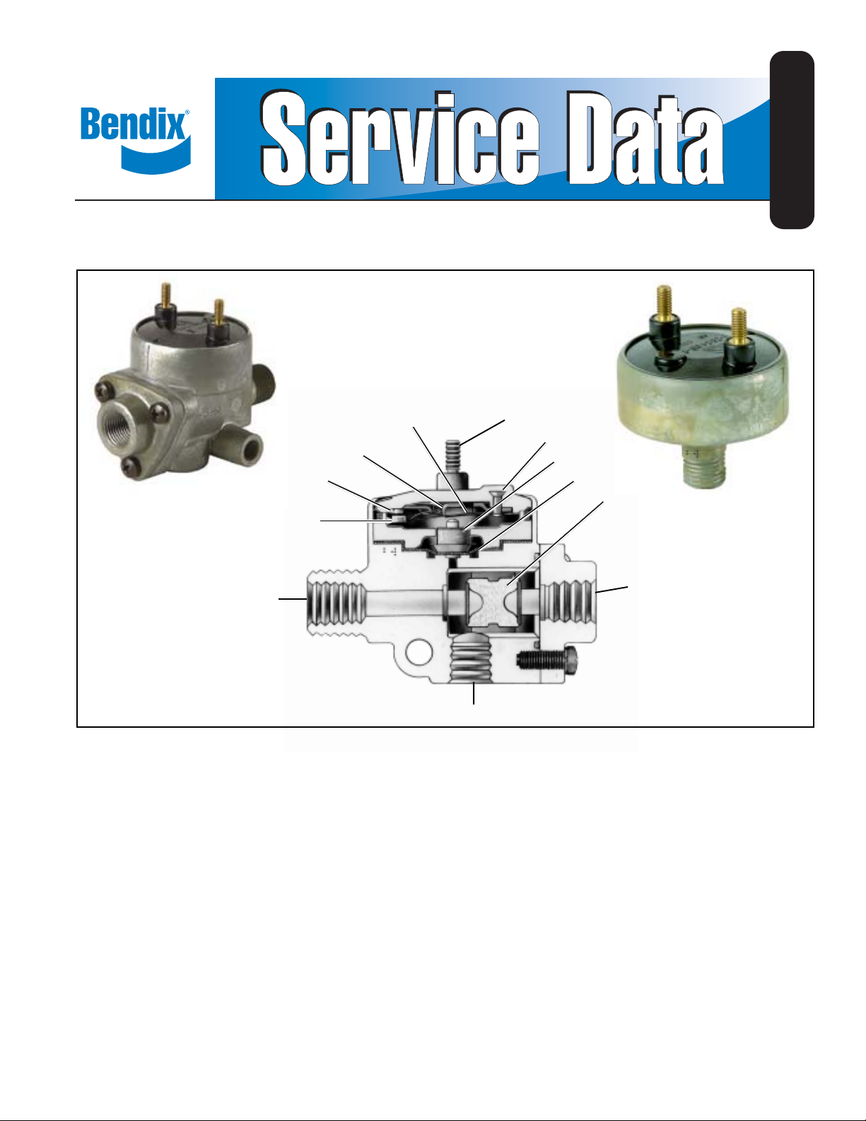
LEAF
SPRING
FULCRUM
CONTACT
STRIP
™
DS-2
VALVE
INLET PORT
FIGURE 1 - DS-2™ COMBINED STOP LIGHT SWITCH & DOUBLE CHECK V ALVE SECTIONAL
SHORTING
BAR
OUTLET PORT
DESCRIPTION
TERMINAL
RIVET
PISTON
DIAPHRAGM
SHUTTLE
(CHECK
VALVE)
The stoplight switch is not a serviceable item; and if found
defective in either device, the complete unit must be replaced.
The Bendix® SL-5™ stop light switch is an electro-pneumatic
5 psi non-grounded switch that operates in conjunction with
the brake valve and stop lights by completing the electrical
circuit and lighting the stop lights when a brake application
is made.
The shuttle valve in the DS-2™ valve is serviceable and may
be replaced.
Both the SL-5™ switch and the DS-2™ valve have been tested
and meet the requirements of FMVSS 121.
The DS-2™ combined stop light switch and double check
valve, as the name implies, combines a SL-5™ stop light
switch with a DC-4™ double check valve to perform the
function of both. It operates in conjunction with the brake
OPERATION
The stop switch mechanism is identical in the SL-5™ switch
and the DS-2™ valve.
valve and hand control valve by directing the flow of air from
whichever delivers the higher pressure into a common delivery
line and to the stop light switch, closing the electrical circuit
to the stop lamps.
When a brake application is made, air pressure from the
brake valve enters the cavity below the diaphragm. The air
pressure below the diaphragm moves the piston until it
contacts the leaf spring. The leaf spring travels past a fulcrum
The stop light switch can be used with either 12 or 24 volt
systems.
at which point the leaf springs snaps a shorting bar which
mates with the contact strips. The stop light electrical circuit
VALVE
INLET
PORT
™
SL-5
STOP
LIGHT
SWITCH
1
Page 2

is completed, lighting the stop lights before the brake
application pressures reach 6 psi.
The snap action spring design minimizes arcing.
The double check valve is activated by air being introduced
through either of the two (2) inlet ports. The greater pressure
pushes the shuttle along its guides and closes the opposite
inlet port. The air is then directed out the common delivery
line and to the stop light switch.
PREVENTIVE MAINTENANCE
Important: Review the Bendix Warranty Policy before
performing any intrusive maintenance procedures. A warranty
may be voided if intrusive maintenance is performed during
the warranty period.
No two vehicles operate under identical conditions; as a
result, maintenance intervals may vary. Experience is a
valuable guide in determining the best maintenance interval
for air brake system components. At a minimum, the
DS-2™/SL-5™ valve should be inspected every 6 months or
1500 operating hours, whichever comes first, for proper
operation and electrical connections. Should the DS-2™/
SL-5™ valve not meet the elements of the operational tests
noted in this document, further investigation and service of
the valve may be required.
OPERATING AND LEAKAGE TEST
1. Install an accurate air gauge in the service line (or brake
chamber). Apply brake valve gradually . S top lamps should
light at 6 psi or less and go out after the brake application
is released. This checks the electrical function of the
stop light switch in either the SL-5™ switch or DS-2
valve.
2. (DS-2™ valve only) Apply the foot valve and coat the
exhaust port of the hand valve (or other alternate source).
Reverse the above, applying the hand valve or other
alternate source and coat the exhaust port of the foot
valve. In either mode a leakage of not more than a 1”
bubble in 5 seconds is permissible.
3. (SL-5™ switch or DS-2™ valve) When pressurized, no
leakage is permitted from the body of the valve or switch.
If the SL-5™ switch or DS-2™ valve does not function as
described above or if leakage is excessive, the valve or switch
should be replaced with a new unit or in the case of the
double check portion of the DS-2™ valve repaired with genuine
Bendix parts.
REMOVING AND INSTALLING
REMOVING
1. Block vehicle wheels or hold by means other than vehicle
service brakes.
2. Disconnect electrical connections from terminal screws.
3. (SL-5™ switch) Remove the switch using a wrench on
the hex portion of the body .
4. (DS-2™ valve) Disconnect air lines and remove the DS-2
valve.
2
INSTALLING
1. Replace the SL-5™ switch or DS-2™ valve in the port
from which it was removed. Do not install with the
terminals pointing down.
2. Secure electrical connections.
3. Reinstall air line connections to DS-2™ valve.
DISASSEMBL Y (Double Check V alve)
1. Remove three cap screws and cap.
2. Remove o-ring seal from cap.
3. Remove shuttle valve.
CLEANING AND INSPECTION
1. Blow dust or other foreign material out of body . Do not
immerse in cleaning fluid.
2. Inspect shuttle valve and o-rings for excessive wear or
deterioration. Inspect valve seats for nicks or burrs.
Replace all parts that were discarded and any parts not
founds to be serviceable during inspection, using only
genuine Bendix replacement parts.
ASSEMBL Y
Before assembling the DS-2™ double check valve, lubricate
all o-rings and o-ring grooves with Bendix silicone lubricant
(Pc. No. 291 126) or equivalent.
NOTE: When using pipe thread sealant during assembly
and installation, take particular care to prevent the
sealant from entering the valve itself. Apply the
sealant beginning with the second thread back from
the end.
™
TEST
Repeat “Operating and Leakage T est”.
WARNING! PLEASE READ AND FOLLOW
THESE INSTRUCTIONS TO AVOID
PERSONAL INJURY OR DEATH:
When working on or around a vehicle, the following
general precautions should be observed at all times.
1. Park the vehicle on a level surface, apply the
parking brakes, and always block the wheels.
Always wear safety glasses.
2. Stop the engine and remove ignition key when
working under or around the vehicle. When
working in the engine compartment, the engine
should be shut off and the ignition key should be
removed. Where circumstances require that the
engine be in operation, EXTREME CAUTION should
be used to prevent personal injury resulting from
contact with moving, rotating, leaking, heated or
electrically charged components.
3. Do not attempt to install, remove, disassemble or
assemble a component until you have read and
thoroughly understand the recommended
procedures. Use only the proper tools and observe
™
all precautions pertaining to use of those tools.
Page 3

4. If the work is being performed on the vehicle’s air
brake system, or any auxiliary pressurized air
systems, make certain to drain the air pressure from
all reservoirs before beginning ANY work on the
vehicle. If the vehicle is equipped with an AD-IS
air dryer system or a dryer reservoir module, be
sure to drain the purge reservoir.
5. Following the vehicle manufacturer’s
recommended procedures, deactivate the electrical
system in a manner that safely removes all
electrical power from the vehicle.
6. Never exceed manufacturer’s recommended
pressures.
7. Never connect or disconnect a hose or line
containing pressure; it may whip. Never remove a
component or plug unless you are certain all
system pressure has been depleted.
8. Use only genuine Bendix
®
replacement parts,
components and kits. Replacement hardware,
tubing, hose, fittings, etc. must be of equivalent
size, type and strength as original equipment and
be designed specifically for such applications and
systems.
9. Components with stripped threads or damaged
parts should be replaced rather than repaired. Do
not attempt repairs requiring machining or welding
unless specifically stated and approved by the
vehicle and component manufacturer.
10. Prior to returning the vehicle to service, make
certain all components and systems are restored to
their proper operating condition.
11. For vehicles with Antilock Traction Control (ATC),
the ATC function must be disabled (ATC indicator
lamp shoud be ON) prior to performing any vehicle
maintenance where one or more wheels on a drive
axle are lifted off the ground and moving.
®
3
Page 4

4
BW1594 © 2006 Bendix Commercial Vehicle Systems LLC All rights reserved. 7/2006 Printed in U.S.A.
 Loading...