

Page 1
®
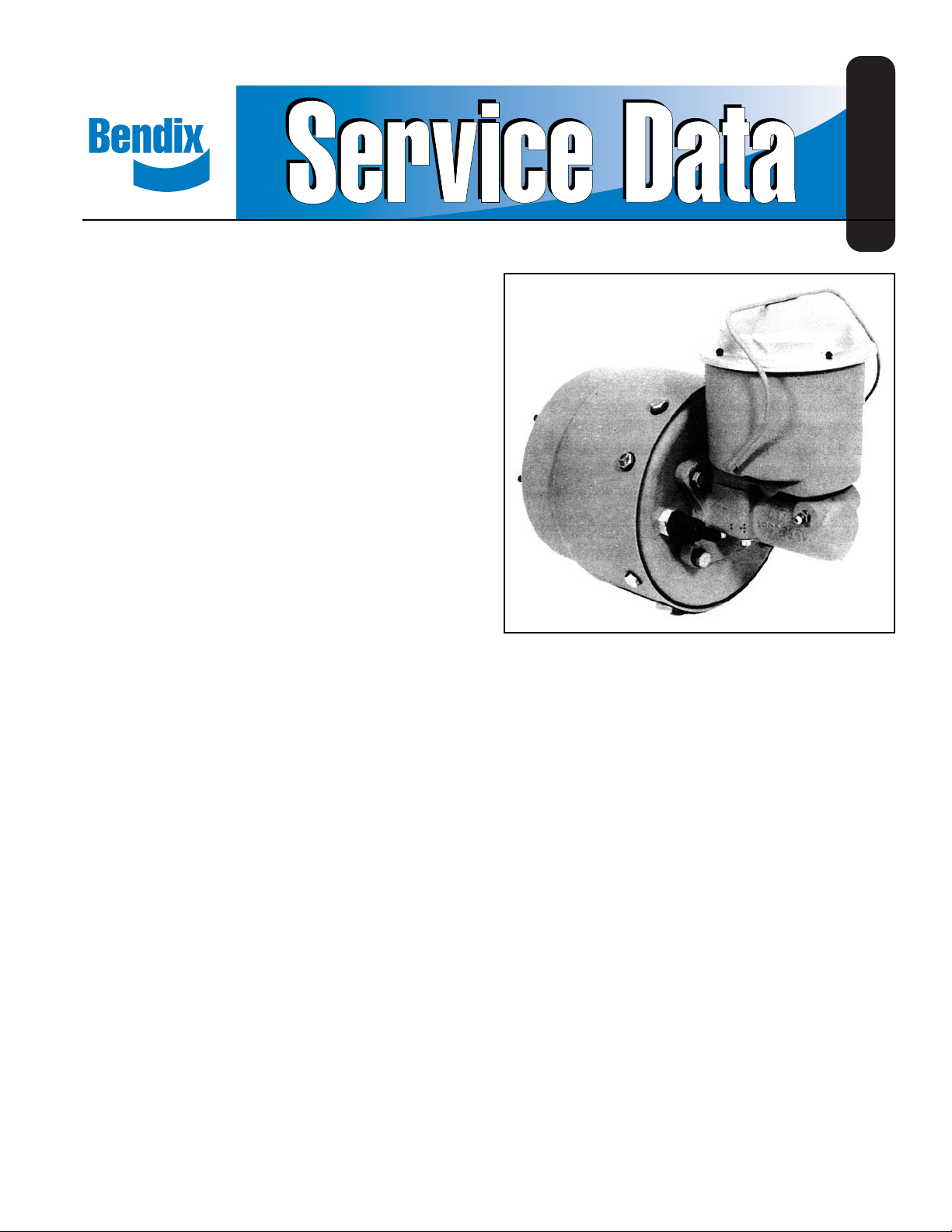
Bendix® AH-4™ Air Hydraulic Intensifier
DESCRIPTION
The AH-4™ is an air-over-hydraulic intensifier available with
pressure ratios of 13.5 to 1, 17 to 1 and 23.5 to 1. The air
chamber is a rotochamber, either type 30, 36 or 50. The
master cylinder design is identical in all units; however , the
master cylinder is available with seals for hydraulic brake
fluid, or for mineral oil. The master cylinder displaces 6 cubic
inches with the type 36 or type 50 actuator and 4.6 cubic
inches with the type 30.
The type 30 unit is designed for dusty operation, as in offhighway , with the non-pressure cavity protected by a tight
fitting head and a filter for breathing non-pressure air.
The master cylinder may have a remote or direct mounted
reservoir. Fig. 1 shows a 23.5 to 1 unit with integral reservoir .
SD-11-1357
OPERATION
The AH-4™ intensifier is normally used to provide hydraulic
pressure to hydraulic disc brakes on an air braked vehicle.
It may be used in any application where it is desired to
“intensify” available air pressure to a higher hydraulic
pressure. 100 psi air pressure introduced to the center port
at the rear of the rotochamber will produce approximately
1,350 psi hydraulic pressure at the master cylinder delivery
port with a type 30 rotochamber, 1,700 psi with a type 36
rotochamber, and approximately 2,350 psi with a type 50
rotochamber.
PREVENTIVE MAINTENANCE
Important: Review the warranty policy before performing
any intrusive maintenance procedures. An extended warranty
may be voided if intrusive maintenance is performed during
this period.
Because no two vehicles operate under identical conditions,
maintenance intervals will vary. Experience is a valuable guide
in determining the best maintenance interval for a vehicle.
Every Month, After 8,000 Miles, or 300 Operating Hours
1. Remove the cover and gasket from the brake fluid
reservoir, t aking extreme care to first remove all dirt and
foreign material so that no foreign material is permitted
to get into the hydraulic fluid. If the fluid lever is low,
proper fluid should be added. CAUTION - The cover and
gasket will each indicate whether hydraulic brake fluid
or mineral oil should be added. The gasket for brake
fluid is black and the gasket for mineral oil is green.
2. Check the stroke warning switch by grasping the switch
extension rod underneath the rubber boot and pulling
firmly. With the ignition turned on, the warning light in
the cab should light. NOTE: If the warning light comes
on during a service application, the vehicle should be
brought in for service immediately .
3. Check tightness of mounting nuts, air and hydraulic
fittings.
Every 12 Months, 100,000 Miles, or 3,600 Operating Hours
1. Disassemble and clean all parts.
2. Install new rotochamber diaphragm, reservoir gasket,
seals or any parts worn or damaged.
OPERA TING AND LEAKAGE TESTS
Operating T est
1. With the air system built up to governor cut-out pressure,
make and hold a full brake application. Hold for at least
5 minutes. Check the rear of the rotochamber and the
rotochamber head vents for air leakage by coating with
a soap solution.
2. While still holding the brake application, check for
hydraulic fluid leaks at all fitting connections and at the
disc brake calipers.
1
Page 2

3. Observe the stroke warning light. If the master cylinder
piston seal leaks, the master cylinder, under sust ained
pressure, will slowly stroke until the stroke warning switch
is activated.
REMOVAL FROM VEHICLE
1. Disconnect the hydraulic line from the delivery port of
the master cylinder and allow the hydraulic fluid to drain
into a suitable receptacle. The drainage may be
expedited by removing the reservoir cover and gasket.
2. Disconnect the air line from the rotochamber, the fluid
supply line from the master cylinder (in the case of
remote mounted reservoirs), and the electrical
connections from the stroke warning switch mounted in
the head of the rotochamber.
3. Remove the nuts from the studs which hold the mounting
brackets and remove the AH-4
vehicle.
™
intensifier from the
INSTALLING ON VEHICLE
1. Remount the AH-4™ intensifier, reconnect the air delivery
line to the rotochamber and the electrical connections
to the stroke warning switch.
2. In the case of remote mounted reservoir, reconnect the
reservoir to the master cylinder.
3. Before adding hydraulic fluid, cycle the AH-4™ intensifier
very carefully by making a very light brake application.
The rotochamber should extend to full stroke and operate
the stroke warning switch, causing the warning light to
come on in the cab. This will test the stroke warning
system. Release the application and reset the stroke
warning switch.
4. Remove plugs, reconnect the fluid lines and bleed the
master cylinder. The master cylinder it self may be bled
by gravity by filling the reservoir and opening the bleeder
fitting opposite the discharge port. When clear fluid flows
from the bleeder fitting, it may be closed. If the rest of
the system needs bleeding, it may be done by opening
the appropriate bleed fitting and cycling the AH-4
intensifier. Hydraulic brake fluid equivalent to DOT 3
specifications should always be used. Some AH-4
intensifier units are designed to be used with mineral
oil, in which case, the reservoir cover will clearly so
designate. Rubber parts for use with mineral oil are color
coded. Reservoir gasket diaphragm is green, seals and
o-rings are brown.
™
™
4
OUTER DIAPHRAGM
CLAMP
INNER
DIAPHRAGM
CLAMP
DIAPHRAGM
GUIDE
5
DIAPHRAGM
7
8
6
FILTER
1
STROKE WARNING SWITCH
2.45
2
FIGURE 1
2
3
PUSH PLATE
PUSH ROD
TERMINAL PER SAE
1858 2 - PLACES
PUSH TO RESET
Page 3

DISASSEMBLY
DISASSEMBLY
Rotochamber from Master Cylinder FIGURE 1
1. Remove four cap screws (1), and remove the master
cylinder from the rotochamber.
Rotochamber
1. Remove the Gap screws (2) which hold the rotochamber
head in the shell and remove the head (6), return spring
(7), and spring guide (8).
2. Remove the nuts (3) from the body which secure the
outer clamp (4) to the body . On some units, one of the
mounting brackets is also retained by three of these
nuts.
3. Place body, open end down on bench and tap the ends
of the studs (5) with a brass drift, lead or plastic hammer .
The studs should be tapped on one side of the air inlet
and then the other alternately , to free the outer clamp.
4. Grasp the push rod and, by pulling and wiggling the
entire assembly consisting of push rod and plate,
diaphragm guide, diaphragm, inner and outer clamps
should ease out of the body .
5. Remove the outer clamp.
6. Remove nuts from inside of diaphragm guide.
7. Disassemble the inner diaphragm clamp, diaphragm,
push plate rod assembly , and diaphragm guide.
8. Remove the stroke warning switch from the rotochamber
head and bench test for electrical integrity . If OK, replace
in head.
Master Cylinder FIGURE 2
1. Clean exterior of master cylinder and drain any
remaining fluid, In the case of remote mounted reservoir,
drain and clean the reservoir.
2. Secure master cylinder in a vise. Depress piston (1)
Fig. 2, at least 1/2 in. and hold. This may be done with
a simple tool as shown in Figs. 3 and 4. Remove the
four self-threading bolts (9) securing the adapter block
or the reservoir to the master cylinder. Remove the
adapter block or reservoir and the compensating valve
(3) and spring (11).
CAUTION The compensating valve must be removed
before any attempt is made to remove the hydraulic
piston assembly (see Fig. 5).
3. Remove retaining ring (8) and stop washer (7).
4. Remove piston holding tool and remove piston (1) and
spring (4).
5. Remove cap nut (10) from adapter block. Remove o-ring
(2) from cap nut and compensating valve seal (5) from
adapter block or reservoir.
FIGURE 2
10
2
6
11
1
4
5
3.19 MAX
3
8
.74
7
3.12 REF
STROKE
.60
9
3
Page 4

FIGURE 3
4-5/8
3/8 X 18 BOLT
3-1/8
C.R.S.
6
4-5/8
ASSEMBLY
Rotochamber
1. Position the diaphragm on end in the inner diaphragm
clamp (Fig. 1). The smaller diameter end of the
diaphragm should be against the diaphragm clamp.
2. Place and install the diaphragm guide within the
diaphragm and over the inner diaphragm clamp studs.
3. Install the push plate push rod assembly within the
diaphragm guide and over the inner diaphragm clamp
studs.
4. Install nuts on the inner diaphragm clamp studs and
tighten securely (55-70 inch pounds)
5. Place the assembly consisting of the push rod, push
plate, diaphragm guide, diaphragm, and inner clamp
inside of the outer clamp.
6. Roll the free end of the diaphragm back and over the
end of the outer diaphragm clamp.
7. Lubricate the inside wall of the body and the rolled
surface of the diaphragm with BW652M T ype 2.
8. Slide the above assembly into the body. The end of the
diaphragm should fit snugly against the shoulder in the
body. Position the outer diaphragm clamp studs through
the holes at the end of the body , install nuts and tighten
securely . Torque to 100-125 inch pounds.
9. Install spring guide, and install spring over push rod.
10.Install cover over push rod and into body . Attach cover
to body with cap screws, tightening securely . T orque to
1 10-150 inch pounds.
FIGURE 4
FIGURE 5
ASSEMBLY
Master Cylinder
1. Wash the cap nut, adapter block, and cylinder castings
with alcohol or mineral spirits and dry thoroughly .
2. Carefully clean the filter screen. (6)
Continued on Page 5.
4
Page 5

3. Install the new o-ring (2) on the cap nut after lubricating
with the fluid to be used in the master cylinder or Dow
Corning 55-M pneumatic grease. Thread the cap nut in
the adapter block and torque to 300 inch pounds.
4. Coat the new compensating seal (5) with fluid or Dow
Corning 55-M pneumatic grease and install in mating
grooves in bottom of adapter block or reservoir.
5. Coat bore in master cylinder with fluid to be used, place
spring (4) in piston assembly (1 ) and slide both into
bore of master cylinder (fig. 6).
7. With piston still depressed, install compensating spring
(1 1 ) and compensating valve (3). Set adapter block (or
reservoir) in place. The master cylinder casting should
preferably be held in a horizontal position for this
operation. Start the four self-threading bolt s (9) by hand
to prevent cross threading and torque to 150- 200 inch
pounds. Care should be taken that the compensating
valve is properly located before the adapter block
or reservoir is located and snugged down (Fig. 9).
The piston may now be released by removing the
retaining tool.
FIGURE 6
6. Place the stop washer (7) and retaining ring (8) over the
center post of the retaining tool, depress the piston (1)
(see Fig. 7). Make certain the retaining ring is properly
seated in its corresponding groove in the master cylinder
casting (see Fig. 8). CAUTION - Keep retaining tool
in place until step 8 is completed!!
FIGURE 8
8. A simple check may be made to determine that the
compensating valve is properly installed. Apply air
pressure on the discharge port of the master cylinder.
With the piston released, air should back flow through
the compensating valve and out the adapter fitting or
reservoir. Depress the piston at least 1/4 in. Air pressure
should now be trapped in the master cylinder and there
should be no evidence of back flow out the adapter
block or reservoir.
FIGURE 7
FIGURE 9
CAUTION - 50 psi air pressure will create approximately
100 pounds of additional reactive force on the piston.
The piston retaining tool should, therefore, be used for
this test.
9. Install the master cylinder on the rotochamber with four
3/8 in. cap screws torqued to 300 inch pounds.
5
Page 6

WARNING! PLEASE READ AND FOLLOW THESE
INSTRUCTIONS TO AVOID PERSONAL INJURY
OR DEATH:
When working on or around a vehicle, the following
general precautions should be observed at all times.
1. Park the vehicle on a level surface, apply the
parking brakes, and always block the wheels.
Always wear safety glasses.
2. Stop the engine and remove ignition key when
working under or around the vehicle. When
working in the engine compartment, the engine
should be shut off and the ignition key should be
removed. Where circumstances require that the
engine be in operation,
be used to prevent personal injury resulting from
contact with moving, rotating, leaking, heated or
electrically charged components.
3. Do not attempt to install, remove, disassemble or
assemble a component until you have read and
thoroughly understand the recommended
procedures. Use only the proper tools and observe
all precautions pertaining to use of those tools.
4. If the work is being performed on the vehicle’s air
brake system, or any auxiliary pressurized air
systems, make certain to drain the air pressure from
all reservoirs before beginning ANY work on the
vehicle. If the vehicle is equipped with an AD-IS
air dryer system or a dryer reservoir module, be
sure to drain the purge reservoir.
EXTREME CAUTION should
5. Following the vehicle manufacturer’s
recommended procedures, deactivate the electrical
system in a manner that safely removes all
electrical power from the vehicle.
6. Never exceed manufacturer’s recommended
pressures.
7. Never connect or disconnect a hose or line
containing pressure; it may whip. Never remove a
component or plug unless you are certain all
system pressure has been depleted.
8. Use only genuine Bendix® replacement parts,
components and kits. Replacement hardware,
tubing, hose, fittings, etc. must be of equivalent
size, type and strength as original equipment and
be designed specifically for such applications and
systems.
9. Components with stripped threads or damaged
parts should be replaced rather than repaired. Do
not attempt repairs requiring machining or welding
unless specifically stated and approved by the
vehicle and component manufacturer.
10. Prior to returning the vehicle to service, make
certain all components and systems are restored to
their proper operating condition.
™
6
BW1455 © 2004 Bendix Commercial Vehicle Systems LLC. All rights reserved. 4/2004 Printed in U.S.A.
 Loading...