

Page 1
®
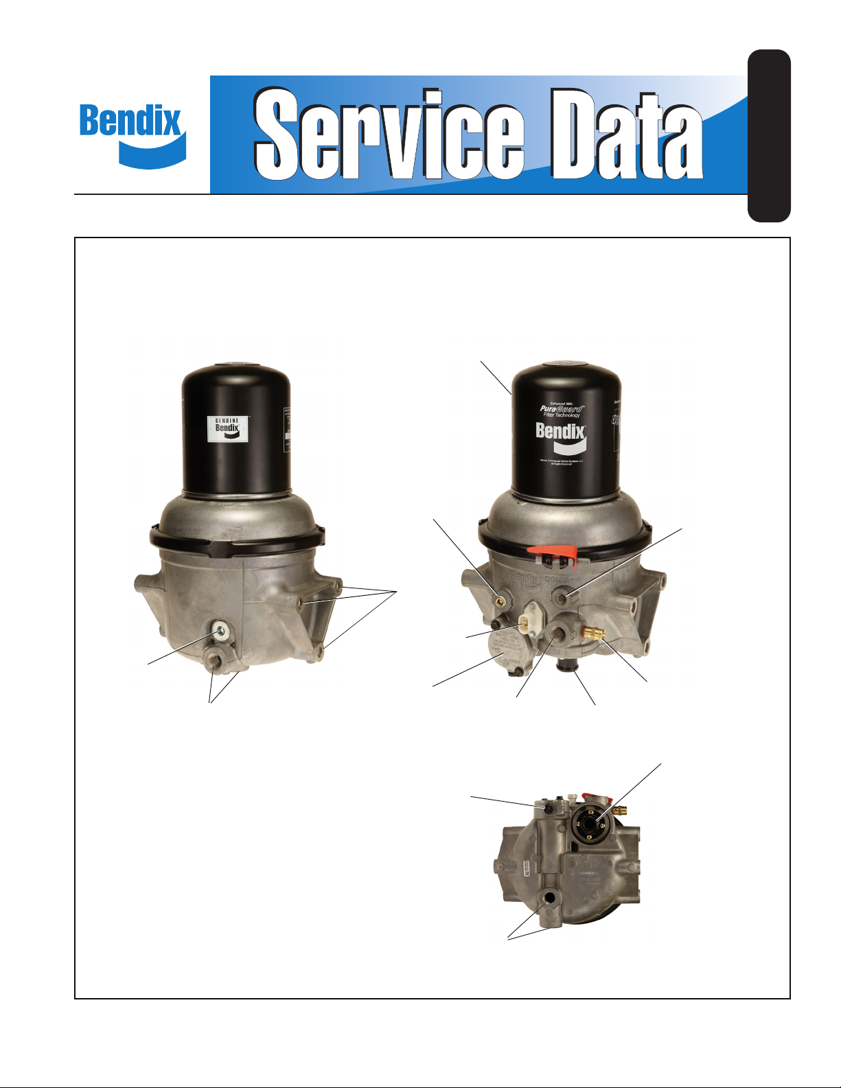
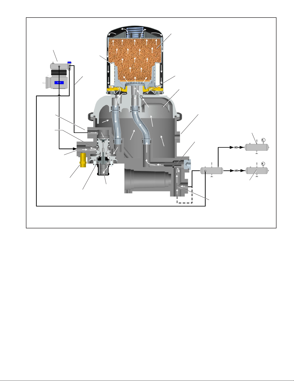
Bendix® AD-9si™ and AD-9si™ PuraGuard® Oil Coalescing Air Dryer
DESICCANT
CARTRIDGE
(PURAGUARD® OIL
COALESCING SHOWN)
SD-08-2433
DELIVERY
CHECK VALVE
COVER
OUT 21
DELIVERY PORTS (2)
PT 22
EXTENDED PURGE
PORT
MOUNTING
HOLES
(3 PER SIDE)
HEATER /
THERMOSTAT
GOVERNOR
(GOVERNOR CUT-OUT
PRESSURE STAMPED
ON COVER)
GOVERNOR
EXHAUST
3
IN 1
SUPPLY FROM
COMPRESSOR
CON 2-4
UNLOADER TO
COMPRESSOR
SAFETY VALVE
PURGE
VALV E
PURGE
VALV E
OUT 21
DELIVERY PORTS (2)
FIGURE 1 - BENDIX® AD-9si™ AND AD-9si™ PURAGUARD® OIL COALESCING AIR DRYER
BOTTOM
VIEW
1
Page 2

GENERAL SAFETY GUIDELINES
WARNING! PLEASE READ AND FOLLOW THESE INSTRUCTIONS
TO AVOID PERSONAL INJURY OR DEATH:
When working on or around a vehicle, the following guidelines should be observed AT ALL TIMES:
▲ Park the vehicle on a level surface, apply the
parking brakes and always block the wheels.
Always wear personal protection equipment.
▲ Stop the engine and remove the ignition key
when working under or around the vehicle.
When working in the engine compartment,
the engine should be shut off and the ignition
key should be removed. Where circumstances
require that the engine be in operation, EXTREME
CAUTION should be used to prevent personal
injury resulting from contact with moving,
rotating, leaking, heated or electrically-charged
components.
▲ Do not attempt to install, remove, disassemble
or assemble a component until you have read,
and thoroughly understand, the recommended
procedures. Use only the proper tools and
observe all precautions pertaining to use of those
tools.
▲ If the work is being performed on the vehicle’s
air brake system, or any auxiliary pressurized air
systems, make certain to drain the air pressure
from all reservoirs before beginning ANY work
on the vehicle. If the vehicle is equipped with a
Bendix® AD-IS® air dryer system, a Bendix® DRM™
dryer reservoir module, or a Bendix® AD-9si™ air
dryer, be sure to drain the purge reservoir.
▲ Following the vehicle manufacturer’s
recommended procedures, deactivate the
electrical system in a manner that safely removes
all electrical power from the vehicle.
▲ Never exceed manufacturer’s recommended
pressures.
▲ Never connect or disconnect a hose or line
containing pressure; it may whip. Never remove
a component or plug unless you are certain all
system pressure has been depleted.
▲ Use only genuine Bendix
®
brand replacement
parts, components and kits. Replacement
hardware, tubing, hose, fi ttings, etc. must be of
equivalent size, type and strength as original
equipment and be designed specifi cally for such
applications and systems.
▲ Components with stripped threads or damaged
parts should be replaced rather than repaired.
Do not attempt repairs requiring machining or
welding unless specifi cally stated and approved
by the vehicle and component manufacturer.
▲ Prior to returning the vehicle to service, make
certain all components and systems are restored
to their proper operating condition.
▲ For vehicles with Automatic Traction Control
(ATC), the ATC function must be disabled (ATC
indicator lamp should be ON) prior to performing
any vehicle maintenance where one or more
wheels on a drive axle are lifted off the ground
and moving.
▲ The power MUST be temporarily disconnected
from the radar sensor whenever any tests USING
A DYNAMOMETER are conducted on a Bendix
®
Wingman® Advanced™-equipped vehicle.
▲ You should consult the vehicle manufacturer's operating and service manuals, and any related literature,
in conjunction with the Guidelines above.
2
Page 3
DESCRIPTION
The function of both the Bendix® AD-9si™ air dryer and the
Bendix® AD-9si™ PuraGuard® oil coalescing air dryer is to
collect and remove air system contaminants in solid, liquid,
and aerosol form before they enter the brake system. The
AD-9si includes a spin-on style cartridge for easy servicing,
and most include a fully integrated governor to control air
system charging.
The air dryer provides clean, dry air to the components of
the brake system, which increases the life of the system
and reduces maintenance costs. The need for daily manual
draining of the reservoirs is eliminated.
The Bendix AD-9si PuraGuard oil coalescing air dryer has
an identical appearance to the standard Bendix AD-9si air
dryer, but contains a coalescing media at the inlet of the
desiccant bed. This coalescing media provides a higher
level of oil removal over the standard AD-9si air dryer.
The AD-9si PuraGuard oil coalescing air dryer has all of
the same functions as the standard AD-9si air dryer and is
used in applications where lower oil concentration levels
are required.
IMPORTANT! When servicing, note that standard AD-9si
air dryers or air dryer cartridges may be serviced with
PuraGuard oil coalescing air dryers or cartridges, however,
PuraGuard oil coalescing air dryers or cartridges MUST
only be serviced with like replacements.
Note: Unless otherwise stated in this document, AD-9si
air dryer refers to both the standard and PuraGuard oil
coalescing air dryer.
The AD-9si air dryer consists of a “spin on” desiccant
cartridge secured to a base assembly. The base assembly
contains a delivery check valve assembly, safety valve,
heater and thermostat assembly, integrated governor (in
most assemblies), threaded air connections, internal purge
volume, and purge valve assembly.
The removable purge valve assembly incorporates the
purge valve mechanism and a turbocharger cut-off feature
that is designed to prevent loss of engine “turbo” boost
pressure during the purge cycle of the AD-9si air dryer. For
ease of maintenance, all replaceable assemblies should
be serviceable without removal of the air dryer from its
mounting on the vehicle — provided adequate clearance
exists between the air dryer and the vehicle components.
Refer to the Preventive Maintenance section of this
document.
BENDIX AD-9si AIR DRYER OPERATION:
GENERAL (Refer to Figures 2 through 5.)
The Bendix AD-9si air dryer is designed to receive
compressed air from the vehicle air compressor, clean and
dry the air, deliver air to the vehicle’s air reservoirs and
control the compressor/dryer charge cycle. The AD-9si
air dryer is available with an internal governor (Figures 2
and 3) or without an internal governor (Figures 4 and 5).
AIR DRYER OPERATION: GENERAL
The Bendix AD-9si air dryer alternates between two modes
or “cycles” during operation: the Charge Cycle and the
Purge Cycle. The following describes these “cycles” of
operation.
Air
Connection
Port ID
IN 1 Inlet Port (air in) 1
OUT 21 Delivery Port Out 2
PT 22 Extended Purge 1
CON 2-4 Governor Unloader 1
3 Governor Exhaust 1
TABLE 1 - PORT DESIGNATIONS
Function/
Connection
Quantity
3
Page 4
COMPRESSOR
OIL
COALESCING
FILTER
DESICCANT
BED
Note 1:
The Bendix® AD-9si™ air dryer purge piston has
a purge control channel drain. This allows any
condensation in this area to ow past a diaphragm
in the top of the purge piston and out through a
channel in the middle of the central bolt of the purge
assembly to be drained. During the purge cycle this
drain is closed.
CONTROL
PORT
TURBO
CUT-OFF
VALVE
(OPEN)
SUPPLY
PORT
SAFETY
VALV E
CONTROL
LINE
PURGE
VALV E
EXHAUST
EXHAUST
GOVERNOR
PURGE
ORIFICE
PURGE AIR
EXTENDED
PURGE
PORT
DELIVERY
CHECK
VALV E
REAR
RESERVOIR
FRONT
RESERVOIR
DELIVERY
PORT
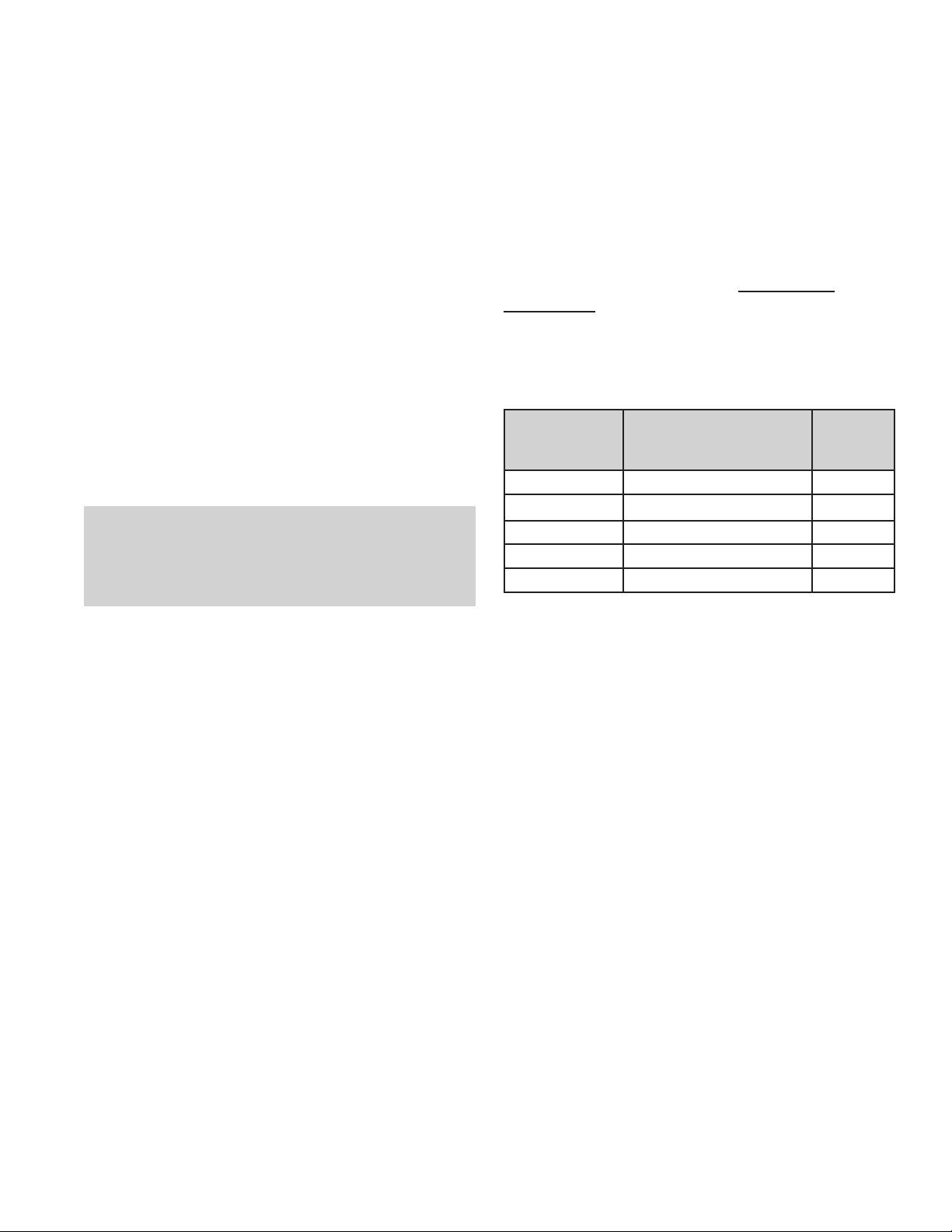
FIGURE 2 - BENDIX® AD-9si™ AIR DRYER WITH GOVERNOR—CHARGE CYCLE
CHARGE CYCLE (Refer to Figures 2 and 4)
When the compressor is running loaded (compressing air),
compressed air ows through the compressor discharge
line to the inlet (IN 1) port of the air dryer body. The
compressed air often includes contaminates such as oil,
oil vapor, water and water vapor.
Traveling through the discharge line and into the air dryer,
the temperature of the compressed air falls, causing
some of the contaminants to condense and drop to the
bottom of the air dryer and purge valve assembly. These
contaminants are ready to be expelled at the next purge
cycle. The air then flows through the inlet tube and
into the desiccant cartridge, where it ows through an
oil separator — or coalescing lter if equipped with a
Bendix® PuraGuard® oil coalescing cartridge — which
removes water in liquid form as well as liquid oil and solid
contaminants.
4
Air then ows into the desiccant drying bed and becomes
progressively more dry as water vapor adheres to the
desiccant material in a process known as adsorption.
Dry air exits the desiccant cartridge, through the outlet tube,
then ows to the delivery check valve. Some air exiting
the desiccant cartridge is diverted through the orice into
the purge volume area. The delivery check valve opens,
supplying air to the two delivery ports. The purge reservoir
lls, storing air that will be used to regenerate the desiccant
during the purge cycle.
The air dryer will remain in the charge cycle until the air
brake system pressure builds to the governor cut-out
setting of approximately 130 psi.
Page 5
DESICCANT
BED
COMPRESSOR
CONTROL
PORT
TURBO
CUT-OFF
VALVE
(CLOSED)
SUPPLY
PORT
SAFETY
VALV E
OIL
COALESCING
FILTER
CONTROL
LINE
PURGE
VALV E
EXHAUST
EXHAUST
GOVERNOR
PURGE
ORIFICE
PURGE AIR
EXTENDED
PURGE
PORT
REAR
RESERVOIR
DELIVERY
CHECK
VALV E
FRONT
RESERVOIR
DELIVERY
PORT
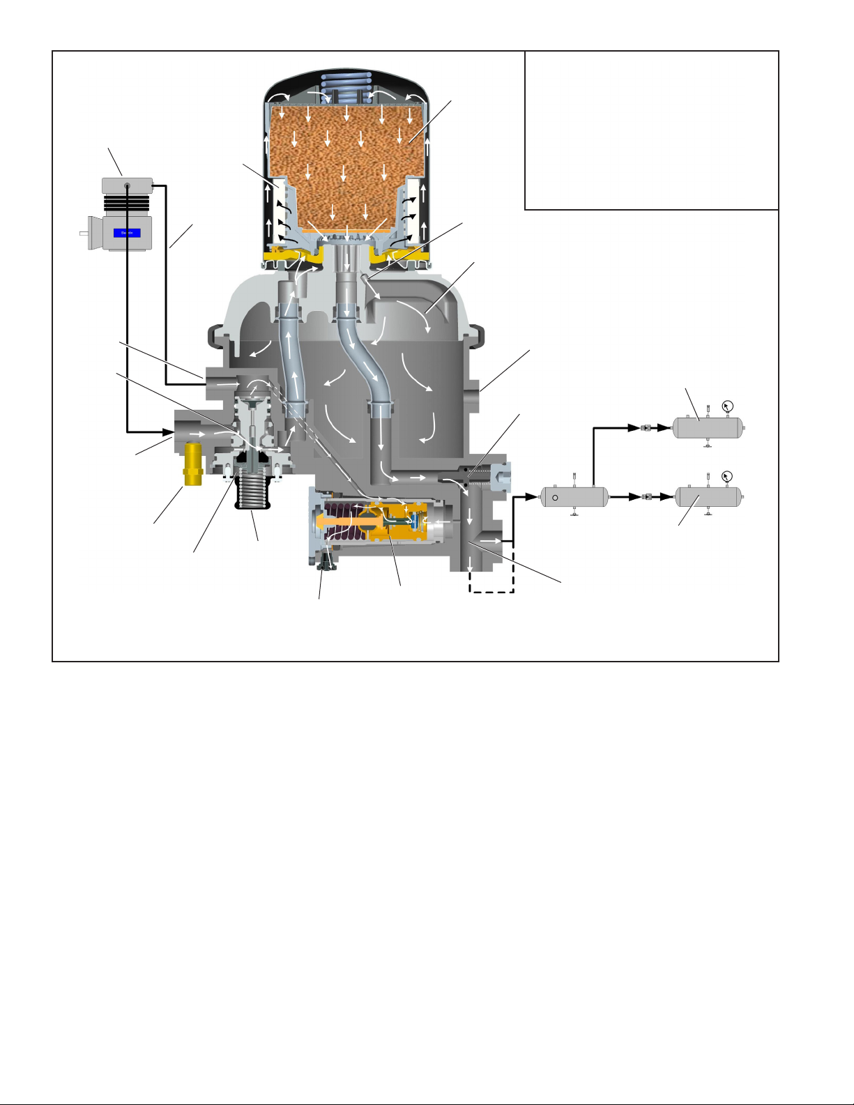
FIGURE 3 - BENDIX® AD-9si™ AIR DRYER WITH GOVERNOR—PURGE CYCLE
PURGE CYCLE (Refer to Figures 3 and 5)
When air brake system pressure reaches the cut-out
setting of the governor, the integral governor unloads the
compressor by supplying a pressure signal through the
control port (CON 2-4). This signal activates the purge
cycle of the air dryer.
The governor unloads the compressor by allowing air
pressure to ll the line leading to the compressor unloader
mechanism. This suspends the delivery of compressed
air to the Bendix® AD-9si™ air dryer.
Similarly, the governor also supplies this air pressure signal
to the purge valve. The pressure moves the air dryer purge
piston down, opening the purge valve to atmosphere and
closing off the compressor air supply to the turbo cut-off
valve (described in the "Turbo Cut-off Feature" section of
this document). Water and contaminants captured are
expelled immediately when the purge valve opens. In
addition, air — which was owing through the desiccant
cartridge — changes direction and begins to ow from the
purge volume toward the open purge valve. Contaminants
collected by the air dryer lters and desiccant are removed
by air owing from the purge volume through the desiccant
drying bed to the open purge valve.
The initial purge and desiccant cartridge decompression
lasts only a few seconds, evidenced by an audible burst
of air at the air dryer exhaust.
5
Page 6

DESICCANT
BED
COMPRESSOR
CONTROL
PORT
TURBO
CUT-OFF
VALVE
(OPEN)
SUPPLY
PORT
SAFETY
VALV E
OIL
COALESCING
FILTER
CONTROL
LINE
PURGE
VALV E
EXHAUST
PURGE
ORIFICE
PURGE AIR
EXTENDED
PURGE
PORT
REAR
RESERVOIR
DELIVERY
CHECK
VALV E
FRONT
RESERVOIR
DELIVERY
PORT
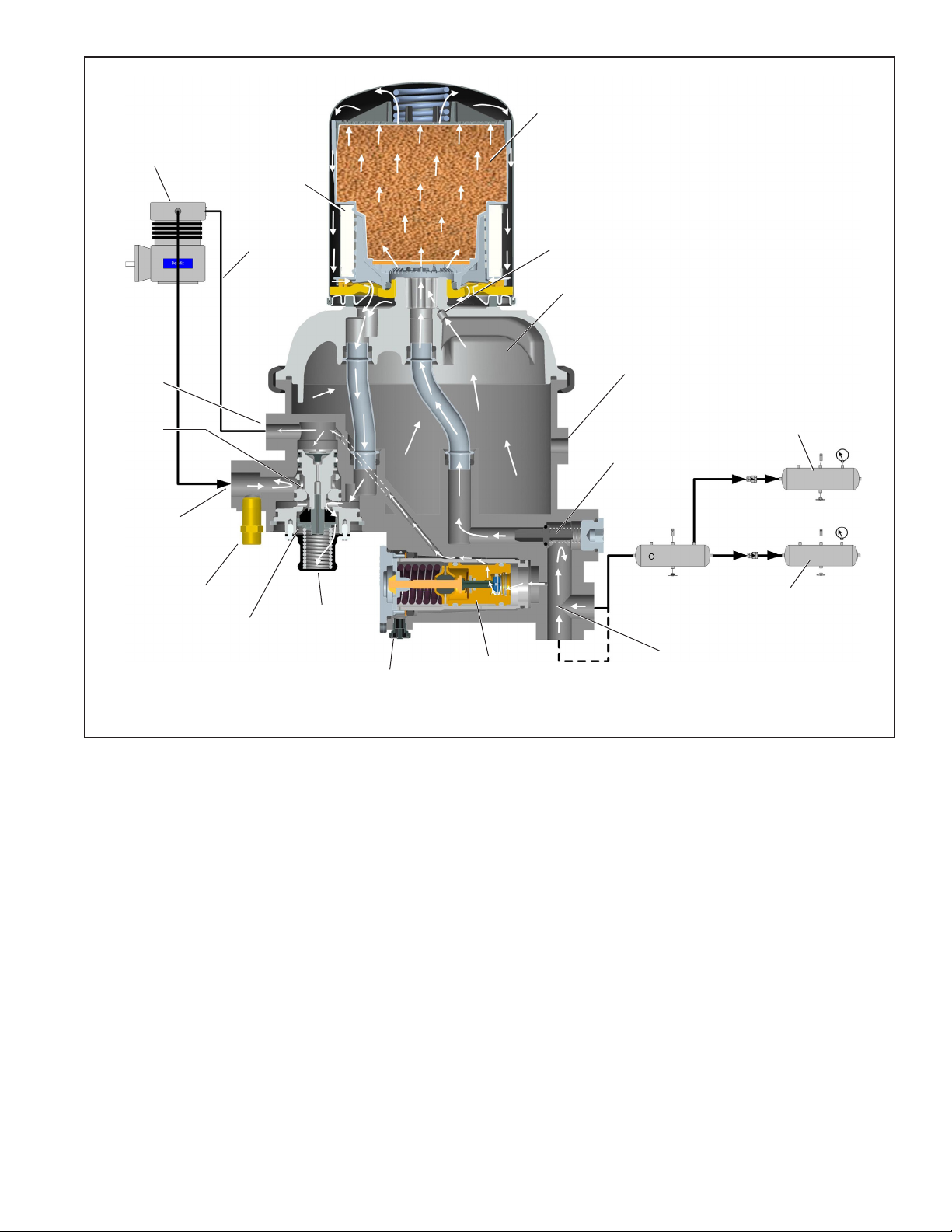
FIGURE 4 - BENDIX® AD-9si™ AIR DRYER WITHOUT GOVERNOR—CHARGE CYCLE
The actual regeneration of the desiccant drying bed begins
as dry air from the purge volume ows through the purge
orice into the desiccant bed. Pressurized air from the
purge volume expands after passing through the purge
The delivery check valve assembly prevents air pressure
in the brake system from returning to the air dryer during
the purge cycle. After the purge cycle is complete, the air
dryer is ready for the next charge cycle to begin.
orice; its pressure lowers and its volume increases. The
ow of dry air through the drying bed regenerates the
desiccant material by removing any water vapor adhering
to it. Approximately 40 seconds are required for the entire
contents of the purge volume of a Bendix® AD-9si™ air
dryer to ow through the desiccant drying bed. This time
will increase if the dryer is tted with an extended purge
reservoir.
6
Page 7
DESICCANT
BED
COMPRESSOR
CONTROL
PORT
TURBO
CUT-OFF
VALVE
(CLOSED)
SUPPLY
PORT
SAFETY
VALV E
OIL
COALESCING
FILTER
CONTROL
LINE
PURGE
VALV E
EXHAUST
PURGE
ORIFICE
PURGE AIR
EXTENDED
PURGE
PORT
REAR
RESERVOIR
DELIVERY
CHECK
VALV E
FRONT
RESERVOIR
DELIVERY
PORT
FIGURE 5 - BENDIX® AD-9si™ AIR DRYER WITHOUT GOVERNOR—PURGE CYCLE
TURBO CUT-OFF FEATURE (Refer to Figures 3
and 5)
The primary function of the turbo cut-off valve is to prevent
loss of engine turbocharger air pressure through the
Bendix® AD-9si™ air dryer when the dryer is in the purge
mode.
At the onset of the purge cycle, the downward travel of the
purge piston is stopped when the turbo cut-off valve (the
tapered portion of the purge piston) contacts its mating
metal seat in the purge valve housing. With the turbo cut-off
valve seated (in the closed position), air in the compressor
discharge line — as well as the AD-9si air dryer inlet port
— cannot enter the air dryer. By completing these actions,
the turbo cut-off effectively maintains turbocharger boost
pressure to the engine.
7
Page 8

PREVENTIVE MAINTENANCE
Important: Review the warranty policy before performing
any intrusive maintenance procedures. An extended
warranty may be voided if intrusive maintenance is
performed during this period. Purge valve and governor
maintenance is permissible during the warranty period
only when using a genuine Bendix® AD-9si™ purge valve
governor kit.
Because no two vehicles operate under identical
conditions, maintenance and maintenance intervals will
vary. Experience is a valuable guide in determining the best
maintenance interval for any one particular operation.
Every 900 operating hours, or 25,000 miles, or three
(3) months:
1. Check for moisture in the air brake system by opening
reservoir drain valves and checking for the presence
of water. If moisture is present, the desiccant cartridge
may require replacement; however, the following
conditions can also cause water accumulation and
should be considered before replacing the desiccant:
A. An outside air source has been used to charge the
system. This air did not pass through the drying
bed of the air dryer.
B. Air usage is exceptionally high and not normal for
a highway vehicle.
This may be due to accessory air demands or some
unusual air requirement that does not allow the
compressor to load and unload (compressing and
non-compressing cycle) in a normal fashion. Check
for high air system leakage. If the vehicle vocation
has changed, it may be necessary to upgrade the
compressor size. Contact the Bendix TechTeam
at1-800-AIR-BRAKE (1-800-247-2725), option 2,
or www.bendix.com for more information.
C. The location of the air dryer is too close to the air
compressor. See the troubleshooting chart at the
end of this document (Symptom 2 - Remedy A).
D. In areas where more than a 30° range of temperature
occurs in one day, small amounts of water can
temporarily accumulate in the air brake system
due to condensation. Under these conditions, the
presence of small amounts of moisture is normal.
HEATER & THERMOSTAT
CONNECTOR
FIGURE 6 - HEATER AND THERMOSTAT CONNECTOR
For Bendix AD-9si air dryers: Preventive Maintenance
is as easy as 1-2-3
Adhering to a preventive maintenance schedule is crucial
to keeping a vehicle’s air system clean and ensuring
superior performance of all components that utilize
system air— such as brakes, emissions equipment
and automated manual transmissions. Depending on
vocation, Bendix recommends a 1-, 2- or 3-year air dryer
cartridge replacement on vehicles equipped with a Bendix®
compressor.
For severe service application — such as residential
refuse trucks or school buses — the air dryer cartridge
should be replaced every year or 100,000 miles; for pick-
up and delivery operations, or for double- and triple-trailer
line haul trucks, every two years or 200,000 miles is the
recommendation. Line-haul operations using a single trailer
should swap the lter out every three (3) years or 300,000
miles. The recommended intervals for trucks equipped with
non-Bendix compressors are six months (50,000 miles),
one year (100,000 miles), and two years (200,000 miles),
respectively.
More frequent intervals may be required depending
on a vehicle’s age, its compressor condition, use of a
non-Bendix compressor, the operating environment, the
vehicle’s vocation, and its usage. In conjunction with these
guidelines, eets can determine the functionality of their
lters by checking for moisture in the air brake system
monthly. If moisture is present, the air dryer cartridge may
require replacement. Reference the Bendix Service Data
Sheet of the specic air dryer for additional information.
(Recommended intervals for trucks equipped with nonBendix compressors are six months (50,000 miles), one
year (100,000 miles), and two years (200,000 miles),
respectively.)
8
Page 9

1. Visually check for physical damage, such as chafed or
broken air and electrical lines, and broken or missing
parts.
2. Check the Bendix® AD-9si™ air dryer and mounting
bolts for tightness. See Figure 1. Re-torque the three
air dryer bolts to 720–912 in-lbs.
3. Perform the Operation & Leakage Tests listed in this
publication.
1. This air dryer is intended to remove moisture and
other contaminants normally found in the air brake
system. Do not inject alcohol, anti-freeze, or other
de-icing substances into — or upstream of — the
air dryer. Alcohol is removed by the dryer, but
reduces the effectiveness of the device to dry air.
Use of these or other substances can damage the
air dryer and may void the warranty.
2. For the Bendix AD-9si air dryer, there are
no serviceable components or maintenance
requirements that require the removal of the clamp
band.
OPERATION & LEAKAGE TESTS (REFER TO THE
TROUBLESHOOTING CHART IN THIS MANUAL)
1. Check all lines and ttings leading to and from the air
dryer for leakage and integrity. Repair any leaks found.
2. Build up system pressure to governor cut-out and note
that the Bendix AD-9si air dryer purges with an audible
escape of air. Watch the system pressure and note the
pressure fall-off for a ten minute period. If pressure
drop exceeds—a) for a single vehicle: 1 psi/minute
from either service reservoir; or b) for tractor trailer: 3
psi/minute from either service reservoir—inspect the
vehicle air systems for leak sources and repair them.
Refer to the Symptoms 1 and 4 in the Troubleshooting
Chart.
3. CAUTION: Be sure to wear safety glasses in case
of a purge blast. Check for excessive leakage around
the purge valve with the compressor in the charge mode
(compressing air). Apply a soap solution to the purge
valve exhaust port and observe that leakage does not
exceed a 1" bubble in one second. If any leakage
exceeds the maximum specied, refer to Symptom 4
in the Troubleshooting Chart.
4. Build up system pressure to governor cut-out and note
that the AD-9si air dryer purges with an audible burst of
air, followed immediately by approximately 40 seconds
of air owing out of the purge valve. Apply and release
the service brakes several times to reduce system
air pressure to governor cut-in. Note that the system
once again builds to full pressure and is followed by a
purge. If the system does not follow this pattern, refer
to Symptoms 5 and 6 in the Troubleshooting Chart.
5. Check the operation of the air dryer heater and
thermostat assembly during cold weather operation as
follows:
A. Electric Power to the Dryer (Refer to Figure 4)
With the ignition or engine kill switch in the RUN
position, check for voltage to the Heater and
Thermostat assembly using a voltmeter or test light.
Unplug the electrical connector at the air dryer and
place the test leads on each of the connections of
the female connector on the vehicle power lead. If
there is no voltage, look for a blown fuse, broken
wires, or corrosion in the vehicle wiring harness.
Check to see if a good ground path exists.
B. Thermostat and Heater Operation
Note: These tests are not possible except in cold
weather operation.
Turn off the ignition switch and cool the Heater and
Thermostat assembly to below 40° Fahrenheit.
Using an ohmmeter, check the resistance between
the electrical pins in the air dryer connector half. The
resistance should be 1.5 to 3.0 ohms for the 12 volt
heater assembly, and 6.0 to 9.0 ohms for the 24 volt
heater assembly.
Warm the Heater and Thermostat assembly to
approximately 90° Fahrenheit and again check the
resistance. The resistance should exceed 1000
ohms. If the resistance values obtained are within
the stated limits, the thermostat and heater assembly
is operating properly. If the resistance values
obtained are outside the stated limits, replace the
heater and thermostat assembly.
GENERAL
When rebuilding or replacing components of the air dryer
and reservoir, use only genuine Bendix® brand replacement
parts. For ease in servicing, the AD-9si air dryer has
been designed so that maintenance kits can be installed
without removing the air dryer from the vehicle. CAUTION:
Always depressurize the air dryer and purge volume
by slowly removing the plug in port 22—and drain
all other reservoirs on the vehicle—to 0 psi before
servicing the air dryer.
If—after completing the routine operation and leakage
tests—it has been determined that one or more components
of the air dryer requires replacement or maintenance, refer
to the Maintenance Kit listing shown in this manual or the
Bendix® Quick Reference Catalog for the appropriate kit(s).
The Quick Reference Catalog (BW1114) can be ordered
and viewed on line at www.bendix.com.
Note: Kits are not available for servicing components inside
the air dryer purge volume.
9
Page 10

DO NOT ATTEMPT TO REMOVE THE CLAMP BAND
THAT RETAINS THE TWO HOUSINGS TOGETHER.
SERIOUS INJURY OR DEATH MAY OCCUR IF THESE
INSTRUCTIONS ARE NOT FOLLOWED COMPLETELY.
BENDIX® AD-9si™ AIR DRYER REMOVAL
This air dryer removal process is presented in the event it
becomes necessary to replace the entire air dryer. Normal
service and parts replacement does not require removal
of the air dryer from the vehicle.
1. Park the vehicle on a level surface and prevent
movement by means other than the brakes.
2. Drain all reservoirs to 0 psi.
3. Identify and disconnect the three air lines from the air
dryer housing.
4. Unplug the vehicle wiring harness from the heater and
thermostat assembly connector.
5. Remove the three mounting bolts that secure the air
dryer to the vehicle.
BENDIX AD-9si AIR DRYER INSTALLATION
1. Install the Bendix® AD-9si™ air dryer on the vehicle using
the three existing 1/2"-13 UNC bolts. Torque the bolts
to 720-912 in-lbs. If replacement bolts are necessary
use grade 5 or above and ensure they are the same
length as those originally used to install the dryer. If
the original air dryer is being reinstalled make sure the
threads in the air dryer housing are in good condition.
2. Reconnect the three air lines to the proper ports on the
air dryer—identied during step 3 of the Bendix AD-9si
removal.
3. Reconnect the vehicle wiring harness to the AD-9si
air dryer heater and thermostat assembly connector
by plugging it into the air dryer connector until its lock
tab snaps in place.
Bendix® AD-9si™ Maintenance Kits
Kit Description Piece No.
Delivery Check Valve Replacement Kit K092011
Desiccant Cartridge Replacement Kit (Standard) 5008414
Desiccant Cartridge Replacement Kit - Bendix AD-9si
PuraGuard® air dryer (can be used to replace the standard
cartridge)
Governor Kit K092010
Heater & Thermostat Replacement (12 volt) 109578
Heater & Thermostat Replacement (24 volt) 109579
Safety Valve Replacement 800155
Silencer Kit (not shown) K021189
Wiring Harness & Splice Kit (not shown) 109871N
Extended Purge Kits (not shown)
93 in3 Reservoir w/ 3/8"-16 U-bolts 5012561N
93 in3 Reservoir w/ 1/2"-13 U-bolts 5005309N
288 in3 Reservoir w/ 3/8"-16 U-bolts 5008972
Purge Valve Assembly
Type Configuration
Bendix® AD-9si™ Air Dryer K022105
Purge Valve Assembly for
climate conditions above
-40°C (-40°F)
Arctic Purge Valve Assembly
for climate conditions of
-40°C to -50°C
(-40°F to -58°F)
AD-9si™ Air Dryer
(Soft Seat Version)
AD-9si™ Air Dryer
(Discharge Line Unloader)
AD-9si Air Dryer K031559
AD-9si Air Dryer
(Soft Seat Version)
AD-9si Air Dryer
(Discharge Line Unloader)
5008414PG
Service Kit
3. Apply and release the service brakes several times to
reduce system air pressure to governor cut-in. Note
that the system once again builds to full pressure and
is followed by a purge at the air dryer exhaust.
4. It is recommended that the total air system be tested
for leakage to ensure that the AD-9si air dryer will not
cycle excessively.
Pc. No.
K031560
K031562
K031561
K031563
4. Before placing the vehicle back into service test the
air dryer operation as indicated in Testing The Bendix
AD-9si Air Dryer section that follows.
TESTING THE BENDIX AD-9si AIR DRYER
Before placing the vehicle into service, perform the
following tests:
1. Close all reservoir drain valves.
2. Build up system pressure to governor cut-out and note
that the Bendix AD-9si air dryer purges (with an audible
burst of air), followed immediately by approximately 40
seconds of air owing out of the purge valve.
10
It is important to read and adhere to the following
instruction, to ensure the brake system operates safely
after bypassing the air dryer.
TEMPORARY AIR DRYER BYPASS
To temporarily bypass the air dryer, follow these procedures
and be sure to adhere to the General Safety Guidelines
outlined elsewhere in this document.
Make sure that all residual pressure has been released.
Slowly loosen the tting that connects the air compressor
discharge line to the air dryer inlet port (IN 1) thereby
allowing any pressure trapped in the air dryer purge
reservoir to escape to the atmosphere. Once the pressure
has escaped and air ow has ceased, remove the tting
Page 11

DESICCANT CARTRIDGE
REPLACEMENT KIT
HEATER & THERMOSTAT REPLACEMENT KIT
GOVERNOR
SCREWS
GOVERNOR
HEATER
SCREWS
O-RING
GOVERNOR KIT
HEATER &
THERMOSTAT
WASHER
O-RING
O-RING
GASKET
O-RING
PURGE
VALV E
SAFETY
VALV E
DELIVERY CHECK VALVE
REPLACEMENT KIT
DELIVERY
SMALL
O-RING
CHECK VALVE
BODY
SPRING
PURGE VALVE
ASSEMBLY
COVER
FIGURE 7 - BENDIX® AD-9si™ AIR DRYER SERVICEABLE COMPONENTS
that connects the air compressor discharge line to the air
dryer inlet tting. Remove the air dryer delivery port tting
(OUT 21). Using any necessary ttings, install a Tee tting
in the air dryer delivery port. To one side of the Tee tting
install the line removed from the air dryer delivery port, to
the opposite side of the Tee tting install the line removed
from the air dryer inlet port. This procedure will allow the
integral governor to continue to regulate the air brake
system pressure properly.
After testing the Tee tting for any air leakage — by using
a soap solution after charging to system cut-out pressure
(a 1” bubble in 10 seconds is acceptable) — the vehicle
may be returned to temporary service.
Note: This is a temporary bypass of the air dryer. Full
repair of the unit must be carried out at the earliest
opportunity. Excessive vehicle operation with the air
dryer bypassed may damage oil sensitive components
such as an automated manual transmission or the
emission system. With the air dryer removed from the
system, contaminants will be entering the air brake system.
Reservoirs will need to be manually drained daily until the
repairs are completed. At the end of each working day,
park the vehicle and slowly drain pressure through the
drain valves — leave open to the atmosphere — for several
hours, if possible. When repairs are carried out, be sure to
check that all reservoirs are emptied of all contaminants.
RETAINING
RING
11
Page 12

If, after bypassing the air dryer, the system pressure still
does not build, use the following procedure to remove,
clean, and reinstall the delivery check valve.
DELIVERY CHECK VALVE CLEANING PROCEDURE
(Note: This is only required if system pressure does
not build after temporary bypass is completed.)
Refer to Figure 7 throughout the following procedure.
De-pressurize the air brake system following the general
safety precautions outlined elsewhere in this document.
Also, always de-pressurize the air dryer purge reservoir
before servicing the air dryer by slowly loosening the tting
that connects the air compressor discharge line to the air
dryer inlet port.
This procedure does not require removal of the Bendix®
AD-9si™ air dryer from the vehicle.
1. Remove the delivery check valve cover, located directly
above the delivery port (OUT 21).
2. The spring/delivery check valve can now be removed.
3. Remove and retain the o-ring from the check valve
body.
CLEANING & INSPECTION
1. Use a suitable solvent to clean all metal parts, and
use a cotton swab to clean the bore (Note: Do not use
abrasives or tools to clean the bore: any scratches
caused may necessitate replacing the Bendix AD-9si
air dryer.) Superficial external corrosion and/or
pitting is acceptable.
ASSEMBLY
1. Lubricate the smaller o-ring and check valve body with
a heavy duty lithium grease.
2. Install the o-ring on the check valve body by sliding the
o-ring over the set of four tapered guide lands. The
o-ring groove holds the o-ring in its correct location.
3. At the other end of the check valve body, the spring is
installed over the set of four straight guide lands. When
the spring has been pushed to the correct location, the
check valve body is designed to hold the end of the
spring in position: be sure that the spring is not loose
before continuing with this installation.
4. Install the assembled check valve body/o-ring/spring
in the delivery port so that the o-ring rests on its seat
and the free end of the spring is visible.
5. Grease the larger o-ring and install it onto the cover.
6. Replace the delivery check valve cover and torque to
720–840 in-lbs.
7. Before placing the vehicle back into service, check
to see that the system pressure now builds to full
operational pressure.
2. Clean the o-rings with a clean dry cloth. Do not use
solvents.
3. Inspect for physical damage to the bore and the check
valve seat. If the bore is damaged (by scratches
etc. that would prevent the delivery check valve from
seating), replace the AD-9si air dryer.
4. Inspect the delivery check valve, o-rings, etc. for wear or
damage. Replace, if necessary, using the check valve
replacement kit available at any authorized Bendix
parts outlets.
®
12
Page 13

SYMPTOM CAUSE REMEDY
1. Dryer is constantly “cycling”
or purging.
BENDIX®AD-9si™ AIR DRYER
TROUBLESHOOTING CHART
A. Excessive system leakage. A. Test for excessive system leakage. Allowable leakage
observed at dash gauge:
- Single vehicle - 1 psi/minute.
- Tractor trailer - 3 psi/minute.
Using soap solution, test vehicle for leakage at ttings,
drain valves and system valves and any accessories (i.e.
air suspension). Repair or replace as necessary and retest
the system.
B. Defective delivery check valve. B. Build system pressure to governor cut-out. Wait 1 minute for
completion of purge cycle. Using soap solution at exhaust of
purge valve, leakage should not exceed a 1" bubble in less
than 5 seconds.
If a rapid loss of pressure is found, the following procedure
will determine if the delivery check valve is malfunctioning:
Build system pressure to governor cut-out and allow a full
minute for the normal dryer purge cycle to empty the purge
reservoir. Switch off the engine and apply and release the
brakes multiple times so that the system pressure reaches
governor cut-in. The purge valve will return to its closed
position. Carefully remove the air dryer cartridge using a
strap wrench and then test for air leaking through the center
of the threaded boss by applying a soap solution to the area.
Replace the delivery check valve if there is excessive leakage
(exceeding a 1" bubble in 5 seconds).
Re-grease the seal on the air dryer cartridge before
reinstalling.
C. Defective governor. C. Check governor at both “cut-in” and “cut-out” position for
proper pressures and excessive leakage at the exhaust.
D. Compressor unloader mechanism
leaking excessively.
D. Remove air strainer, or tting, from compressor inlet cavity.
With compressor unloaded, check for unloader piston
leakage. Slight leakage is permissible.
13
Page 14

BENDIX®AD-9si™ AIR DRYER
TROUBLESHOOTING CHART
SYMPTOM CAUSE REMEDY
2. Water in vehicle reservoirs. A. Maximum air dryer inlet temperature is
exceeded due to improper discharge
line length.
B. Ambient temperature exceeds 125°F. B. Relocate the air dryer away from excessive heat source.
C. Air system charged from outside
air source (outside air not passing
through air dryer).
D. Excessive air usage - Air dryer not
compatible with vehicle air system
requirement (improper air dryer/
vehicle application).
E. Desiccant requires replacement. E. Replace desiccant cartridge assembly. See
F. Air dryer not purging. F. Refer to Symptom 6.
G. Purge (air exhaust) time insufcient
due to excessive system leakage.
3. Safety valve on air dryer
“popping off” or exhausting
air.
4. Constant exhaust of air at air
dryer purge valve exhaust
or unable to build system
pressure. (Charge mode.)
A. Safety valve setting too low (<150 psi). A. Replace safety valve.
B. System pressure too high (>135 psi). B. Test with accurate gauge. Replace the governor cartridge if
C. Excessive pressure pulsations from
compressor. (Typical single cylinder
type).
A. Air dryer purge valve leaking
excessively.
B. Purge valve frozen open - faulty heater
and thermostat, wiring, blown fuse.
C. Defective AD-9si™ air dryer delivery
check valve.
D. Leaking turbo cut-off valve. D. Repair or replace purge valve assembly.
E. Defective governor. E. Check the governor at both “cut-in” and “cut-out” positions
F. Leaking purge valve control piston
seals.
A. Check for excessive carbon build-up in compressor discharge
line. Replace if required. Make certain that discharge line
length is at least 6 ft. Increase discharge line length and/or
diameter to reduce air dryer inlet temperature.
C. If system must have outside air ll provision, outside air should
pass through the air dryer.
D. Refer to the
for proper application of the Bendix® AD-9si™ air dryer. An
extended purge reservoir may be added for higher air usage
vehicles, such as city buses and construction vehicles.
If the vehicle is equipped with high air usage accessories
such as trailer pump-off systems or central tire ination, the
air for these accessories must by-pass the air dryer.
Bendix® Air Dryer Application Guideline
(BW2600)
Bendix Air Dryer
Application Guideline
intervals.
G. Refer to Symptom 1.
necessary.
C. Increase the volume in the discharge line. This can be
accomplished by adding a 90 cubic inch (or larger) reservoir
between the compressor and the AD-9si air dryer.
A. With compressor loaded, apply soap solution on purge valve
exhaust, to test for excessive leakage. Repair or replace
purge valve as necessary.
B. Refer to paragraph 5 of the
heater and thermostat test.
C. Refer to Symptom 1, Remedy B.
for proper pressures and excessive leakage at the exhaust.
F. Repair or replace purge valve assembly.
(BW2600) for recommended service
Operation and Leakage Tests
for
14
Page 15

BENDIX®AD-9si™ AIR DRYER
TROUBLESHOOTING CHART
SYMPTOM CAUSE REMEDY
5. Cannot build system air
pressure.
6. Air dryer does not purge or
exhaust air.
7. Desiccant material being
expelled from air dryer purge
valve exhaust (may look like
whitish liquid or paste or
small beads.)
8. Unsatisfactory desiccant life. A. Excessive system leakage. A. Refer to Symptom 1, Remedy A.
9. “Pinging” noise excessive
during compressor loaded
cycle.
10. The air dryer purge piston
cycles rapidly in the
compressor unloaded (noncompressing) mode.
A. Supply pressure to the air dryer is not
sufcient.
B. Kinked or blocked (plugged) discharge
line.
C. Excessive bends in discharge line
(water collects and freezes).
D. Refer to Symptom 4. D. Refer to Symptom 4, Remedy A.
E. Refer to Symptom 7. E. Refer to Symptom 7, Remedies A and B.
A. Faulty air dryer purge valve. A. After determining that air reaches the purge valve piston by
B. See Causes B, E, and F for Symptom
#4.
A. Faulty dryer cartridge. A. Replace the Bendix® AD-9si™ air dryer cartridge or AD-9si air
B. Excessive dryer vibration. B. Check the AD-9si air dryer mounting for looseness or
B. Wrong vehicle application for AD-9si™
air dryer.
C. Compressor passing excessive oil. C. Check for proper compressor installation; if symptoms
A. Ensure the supply pressure to the air dryer is greater than
110 psi during the system charge.
B. Check to determine if air passes through discharge line.
Check for kinks, bends, excessive carbon deposits, or ice
blockage.
C. Discharge line should be constantly sloping from compressor
to air dryer with as few bends as possible.
installing a Tee tting with a pressure gauge into the control
port, repair purge valve if necessary.
B. Refer to Symptom 4, Remedies B, E, and F.
dryer.
damage. Repair mounting and replace cartridge.
B. Refer to Symptom 2, Remedy C.
persist, replace compressor. Refer to
Troubleshooting Guide for Air Brake Compressor
A. Single cylinder compressor with high
pulse cycles.
A. Compressor fails to “unload”. A. Check the air hose from the AD-9si air dryer control port to the
A. A slight “pinging” sound may be heard during system build-
up when a single cylinder compressor is used. If this sound
is deemed objectionable, it can be reduced substantially by
increasing the discharge line volume.
This can be accomplished by adding a 90 cubic inch (or
larger) reservoir between the compressor and the AD-9si air
dryer.
compressor for a missing, kinked, or restricted line. Install or
repair the air hose. Repair or replace the compressor unloader.
Bendix® Advanced
(BW1971).
15
Page 16

Log-on and Learn from the Best
cled paper
On-line training that's available when you are 24/7/365.
Visit www.brake-school.com.
SD-08-2433 ©
2014 Bendix Commercial Vehicle Systems LLC, a member of the Knorr-Bremse Group • 9/14 • All Rights Reserved
Printed on recy
 Loading...