

Page 1
DE
Kurzanleitung/Quickstart guide
EN
ISOMETER® isoUG425
DE
Isolationsüberwachungsgerät für ungeerdete
Gleichspannungsnetze (IT-Systeme) bis 120 V
Software-Version: D0476 V2.xx
Diese Kurzanleitung richtet sich an Fachpersonal der Elektrotechnik und Elektronik. Sie ersetzt nicht das Handbuch. Stellen Sie sicher, dass das Personal das
Handbuch gelesen und alle Hinweise, die die Sicherheit betreffen, verstanden
hat. Das Handbuch finden Sie unter:
www.bender.de/service-support/downloadbereich
1. Bestimmungsgemäße Verwendung
Das ISOMETER® überwacht den unsymmetrischen Isolationswiderstand RF
von ungeerdeten DC-Hauptstromkreisen (IT-Systemen) mit Netznennspannungen von DC 12 …120 V. Die maximal zulässige Netzableitkapazität C
trägt 50 μF.
Die bei einem Isolationsfehler eines Netzleiters gemessene
Verlagerungsspannung wird messtechnisch ausgewertet.
Durch das passive Messverfahren können nur
unsymmetrische Isolationsfehler erfasst werden. Gleich
große Isolationsfehler von der Plus- und Minusleitung gegen
Erde (d.H. symmetrische Fehler) werden nicht erfasst.
Bei einer Alarmmeldung des ISOMETER® sollte der
Isolationsfehler schnellstmöglich beseitigt werden.
e
be-
Die Meldung des ISOMETER® muss auch dann akustisch und/
oder optisch wahrnehmbar sein, wenn das Gerät innerhalb
eines Schaltschrankes installiert ist.
isoUG425_D00220_02_Q_DEEN / 05.2018
1
Page 2

2. Sicherheitshinweise allgemein
Montage, Anschluss und Inbetriebnahme nur durch Elektrofachkraft!
Beachten Sie unbedingt:
die bestehenden Sicherheitsvorschriften (DIN EN 50110)
das beiliegende Blatt „Sicherheitshinweise für Bender-Produkte“.
3. Funktionsbeschreibung
Das ISOMETER® misst ab einer Mindestnetznennspannung den unsymmetrischen Isolationswiderstand R
und Erde (PE). Der Effektivwert und der DC Wert der Netznennspannung U
zwischen L+ und L- sowie die Verlagerungsspannungen U
und Erde) und U
(zwischen L- und Erde) werden ebenfalls gemessen.
L-e
Es besteht die Möglichkeit, den ermittelten Fehler bzw. den fehlerbehafteten
Leiter per Menü einem Alarmrelais zuzuweisen. Verletzen die Werte R
die aktivierten Ansprechwerte des Menüs "AL", erfolgt eine Meldung über
U
n
die LEDs sowie die Relais „K1“ und „K2“ gemäß den Einstellungen in der Meldezuordnung im Menü "out". Dort kann auch die Arbeitsweise der Relais
(n.o./n.c.) eingestellt sowie der Fehlerspeicher „M“ aktiviert werden.
Verletzen die Werte R
zuzüglich Hysterese) ununterbrochen nicht mehr für die Dauer t
die Alarmrelais wieder in die Ausgangslage zurück und die Alarm LEDs
„AL1“/„AL2“ erlöschen.
Ist die Fehlerspeicherung aktiviert, bleiben die Alarmrelais in Alarmstellung
und die LEDs leuchten, bis die Reset-Taste „R“ betätigt oder die Versorgungsspannung U
Mit der Test-Taste „T“ kann die Gerätefunktion geprüft werden. Die Gerätepa-
unterbrochen wurde.
s
rametrierung erfolgt über das LC-Display und die frontseitigen Bedientasten
und kann durch ein Passwort geschützt werden. Das Gerät kann auch über
den BMS-Bus, z. B. mittels eines BMS-Ethernet-Gateway (COM460IP) oder
Modbus RTU parametriert werden.
zwischen dem zu überwachenden Netz (L+, L-)
F
(zwischen L+
L+e
oder
F
oder Un ihren jeweiligen Rückfallwert (Ansprechwert
F
, schalten
off
n
2
isoUG425_D00220_02_Q_DEEN / 05.2018
Page 3
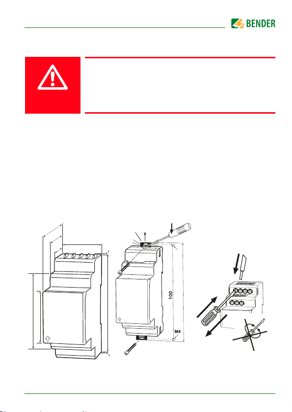
4. Montage und Anschluss
Gefahr eines elektrischen Schlages!
Sorgen Sie für Spannungsfreiheit im Montagebereich
und beachten Sie die Regeln für das Arbeiten an elektri-
GEFAHR
Beachten Sie den Mindestabstand zu benachbarten Geräten:
Seiten 0 mm, oben 20 mm, unten 20 mm!
Montage auf Hutschiene:
Rasten Sie den rückseitigen Montageclip des Geräts auf der Hutschiene so ein,
dass ein sicherer und fester Sitz gewährleistet ist.
Schraubmontage
Bringen Sie die rückseitigen Montageclips (2. Montageclip erforderlich, siehe
Bestellinformation) mittels Werkzeug in eine über das Gehäuse hinaus ragende Position. Befestigen Sie das Gerät mit zwei M4-Schrauben.
schen Anlagen.
74,5
47,5
36
31,1
67,5
45
isoUG425_D00220_02_Q_DEEN / 05.2018
Zubehör
2
93
2
Klick
M4
2
107
1
3
3
Page 4
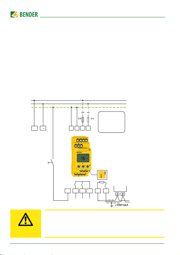
Anschlussbild
Die Versorgungsspannung Us an A1/A2 kann an die Systemspannung (L+/L-)
angeschlossen werden, wenn die Systemspannung ≥ DC 24 V ist. Ansonsten
ist eine separate Versorgung erforderlich. Die Klemmen „A1“ und „A2“ sind an
die Versorgungsspannung U
die Zuleitung ist mit Schutzeinrichtungen zum Schutz bei Kurzschluss zu versehen (Empfehlung: Schmelzsicherung 6 A). Für den Anschluss der Klemmen
„L+“ und „L–“ an das zu überwachende IT-System kann entsprechend
DIN VDE 0100-430 auf Schutzeinrichtungen zum Schutz bei Kurzschluss verzichtet werden, wenn die Leitung oder das Kabel so ausgeführt ist, dass die
Gefahr eines Kurzschlusses auf ein Mindestmaß
beschränkt ist.
L+
L
Test/Reset
gemäß DIN VDE 0100-430 anzuschließen, d. h.
s
L+
L-
PE
Die Versorgungsspannung
U
S
an A1 / A2 kann an die
U
s
Systemspannung (L+ / L-)
angeschlossen werden, wenn
die Systemspannung
≥ DC 24 V ist. Ansonsten ist
eine separate Versorgung
A1 A2
E
T/R
KE
EKEA1A2
L+ L-
ON
<
ISOMETER
TR
T/R
K1 K2
14 24 11
14 24
erforderlich.
k
AL1 AL2
isoUG425
k
MENU
11
R
on
B
A
off
R
COM460IP
B
A
RS-485
VORSICHT
4
Mit einer externen Test/Reset-Taste darf nur ein ISOMETER®
angesteuert werden. Eine galvanische Parallelschaltung
mehrerer Test- oder Reset-Eingänge für Sammelprüfungen
von ISOMETER®n ist nicht erlaubt.
isoUG425_D00220_02_Q_DEEN / 05.2018
Page 5
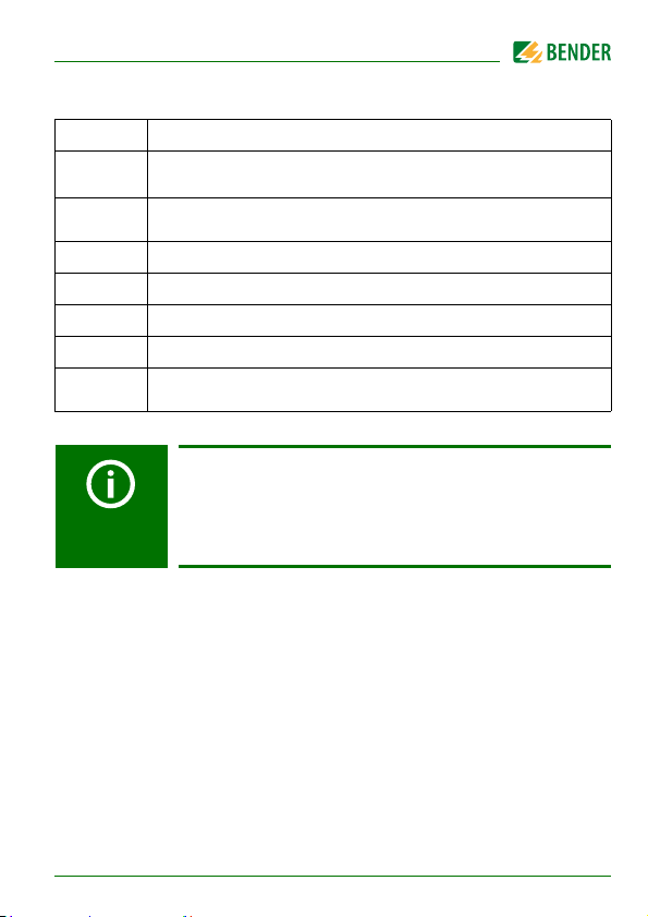
Legende zum Anschlussbild
Klemme Anschlüsse
A1, A2
E, KE
L+, L– Anschluss an das zu überwachende DC-Netz.
11, 14 Anschluss Alarmrelais „K1“
11, 24 Anschluss Alarmrelais „K2“
Anschluss an die Versorgungsspannung Us über Schmelzsicherung. Bei Versorgung aus IT-System beide Leitungen absichern.*
Jede Klemme jeweils separat an PE anschließen:
Gleichen Leitungsquerschnitt wie bei „A1“, „A2“ verwenden.
T/R Anschluss für externe kombinierte Test- und Reset-Taste.
RS-485-Kommunikationsschnittstelle mit zuschaltbarem
A, B
Terminierungswiderstand.
* Für UL-Anwendungen:
Nur 60/75°C-Kupferleitungen verwenden!
Die Versorgungsspannung U
ist bei UL- und CSA-
s
Applikationen zwingend über 5-A-Vorsicherungen
zuzuführen.
isoUG425_D00220_02_Q_DEEN / 05.2018
5
Page 6

5. Fehlercodes
Sollte wider Erwarten ein Gerätefehler auftreten, erscheinen im Display
Fehlercodes:
Fehlercode Bedeutung
E.01
E.02 Das überwachte DC-Netz hat die falsche Polarität.
E.05
E.08 Während dem Gerätetest wurde ein Kalibrierfehler erkannt
E.xx Gerätefehler - Kontakt zum Bender-Service aufnehmen.
Die Verbindung der Anschlüsse „E“ oder „KE“ zu Erde ist unterbrochen.
Messtechnikfehler/Kalibrierung ungültig für die aktuelle
Software-Version
6
isoUG425_D00220_02_Q_DEEN / 05.2018
Page 7
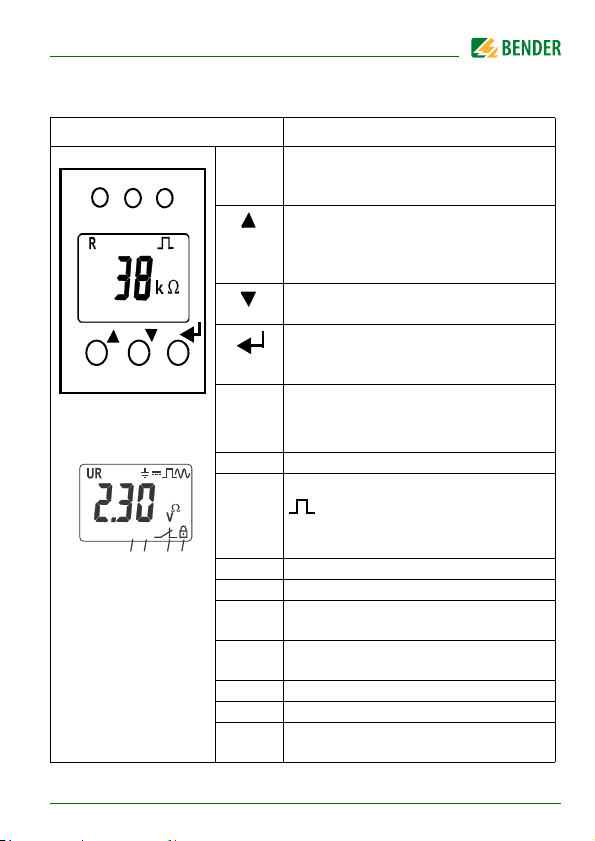
6. Genutzte Display-Elemente
ON AL1 AL2
T
MENU
R
+
test onoff MAdr
L1L2
C
<
>
s
kM %
Fµ
{
{
{
{
4
Hz
{
Gerätefront/Display Funktion
ON
grün - On
AL1
gelb - Alarm
AL2
gelb - Alarm
Aufwärts-Taste
Test-Taste ( > 1,5 s betätigen)
T
Bei gedrückter Test-Taste werden die Display Elemente angezeigt.
Abwärts-Taste
Reset-Taste ( > 1,5 s betätigen)
R
ENTER
Zuordnung gemäß
Tabelle auf Seite 10
1
10
9
isoUG425_D00220_02_Q_DEEN / 05.2018
3
2
{
8
567
MENU
MENU-Taste ( > 1,5 s betätigen)
1U : Netznennspannung U
R : Isolationswiderstand R
C : Netzableitkapazität C
2 Überwachter Leiter
3 = : Spannungsart DC
: Störungsfreie Messwert-
aktualisierung
=~ : Spannungsart RMS
4 Messwerte und Einheiten
5 Passwortschutz ist aktiviert.
6 Im Menübetrieb wird die Arbeitswei se des
jeweiligen Alarmrelais angezeigt.
7 Kommunikationsschnittstelle
mit Messwert: isoData-Betrieb
8 Fehlerspeicher ist aktiviert.
9 Zustandssymbole
10 Kennung für Ansprechwerte und
Ansprechwertverletzung
n
F
e
7
Page 8
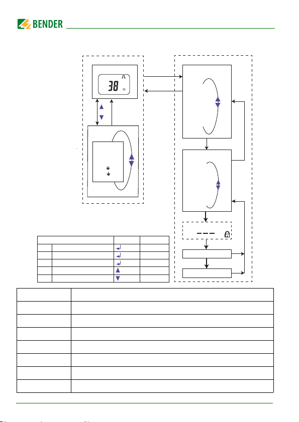
7. Menü-Übersicht
Messwertanzeige
Standardanzeige
R
k
Enter
oder
t > 5 Min.
Menü
Esc
Menüauswahl
AL
out
t
SEt
InF
HiS
ESC
Funktion Taste Betätigung
Enter
Auswahl, Eingabe bestätigen
Menü
Menü aufrufen
Esc
Menüpunkt verlassen
Test
Gerätetest starten
Reset
Fehlerspeichern löschen
Menüpunkt Parameter
AL
out
SEt
InF
HiS
ESC
Ansprechwerte abfragen und einstellen
Fehlerspeicher, Alarmrelais und Schnittstelle konfigurieren
Verzögerungszeiten und Selbsttestzyklus einstellen
t
Gerätesteuerung parametrieren
Software-Version abfragen
Historienspeicher abfragen und löschen
Zur nächsthöheren Menüebene bewegen
8
R [ kΩ ]
U L1 L2 [ V
U L1 L2 [ V
UL1 [ V
UL2 [ V
]
RMS
]
DC
]
DC
]
DC
/ MENU Kurz
/ MENU
/ MENU
/ T
/ R
Enter
> 1,5 s
> 1,5 s
> 1,5 s
> 1,5 s
Parameterauswahl
P
. . .
P
ESC
Optionales Passwort
Parameter editieren
Parameter speichern
1
n
Enter
Enter
Enter
Esc
Esc
isoUG425_D00220_02_Q_DEEN / 05.2018
Page 9
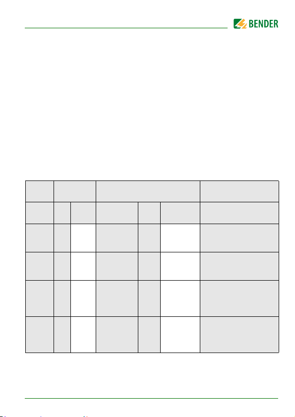
7.1 Menü „AL"
Ansprechwerteinstellung
Im Ansprechwertmenü „AL“ finden sich die beiden Parameter „R1“ und „R2“
für die Überwachung des Isolationswiderstands R
ßer als der Wert R2 eingestellt werden. Erreicht oder unterschreitet der Isolationswiderstand R
Alarmmeldung. Überschreitet R
die aktivierten Werte R1 oder R2, führt dies zu einer
F
die Werte R1 oder R2 zuzüglich des Hystere-
F
sewertes (siehe Tabelle unten), wird der Alarm gelöscht.
Ebenfalls im Ansprechwertmenü „AL“ können die beiden Parameter („U <“
und „U >“) zur Überwachung der Netznennspannung U
tiviert werden. Der maximale Unterspannungswert ist durch den Überspannungswert begrenzt.
Display Aktivierung Einstellwert Beschreibung
. Der Wert R1 kann nur grö-
F
aktiviert bzw. deak-
n
FAC Ke Bereich
R1 < R2 … 100 50 kΩ
R2 < 1 … R1 25 kΩ
U < off 8 … U> 8 V
U > off
FAC = Werkseinstellung; Ke = Kundeneinstellungen
isoUG425_D00220_02_Q_DEEN / 05.2018
U<… 144
FAC Ke
140 V
Voralarmwert R
Hys. = 25 %/min. 1 kΩ
Alarmwert R
Hys. = 25 %/min. 1 kΩ
Alarmwert
Unterspannung DC
Hys . = 5 %/min. 1 V
Alarmwert
Überspannung DC
Hys. = 5 %/min. 1 V
an1
an2
9
Page 10
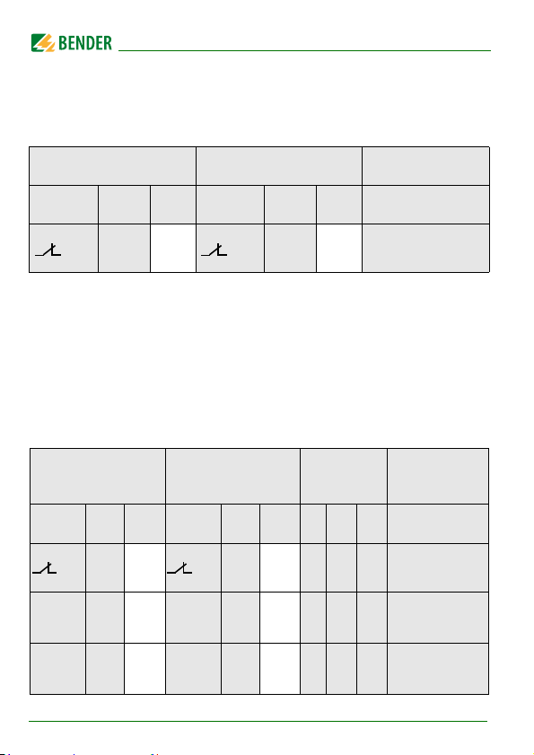
7.2 Menü „out"
1
2
1
Err2Err
Relais Arbeitsweise-Konfiguration
Relais K1 Relais K2 Beschreibung
Display FAC Ke Display FAC Ke
n.c. n.c.
FAC = Werkseinstellung; Ke = Kundeneinstellungen
Arbeitsweise Relais
n.c / n.o.
Relais-Meldezuordnung „r1" und „r2" und LED-Zuordnung
In der Meldezuordnung werden mit der Einstellung "on" die einzelnen Meldungen / Alarme dem jeweiligen Relais zugeordnet. Die LED-Anzeige ist direkt den Meldungen zugeordnet und hat keinen Bezug zu den Relais.
Kann das Gerät einen unsymmetrischen Isolationsfehler dem entsprechenden Leiter (L+ oder L-) zuordnen, setzt es nur die jeweilige Meldung.
K1 „r1“ K2 „r2“ LEDs
Display
r1
+R1 < Ω
r1
- R1 < Ω
FAC Ke
off on
on
on
Display
r2
+R1 < Ω
r2
-R1 < Ω
FAC Ke
off
off
10
ON AL1 AL2
isoUG425_D00220_02_Q_DEEN / 05.2018
Meldungs-
beschreibung
Gerätefehler E.xx
Voralarm R1
Fehl er RF an L+
Voralarm R1
Fehl er RF an L-
Page 11

K1 „r1“ K2 „r2“ LEDs
Meldungs-
beschreibung
Display
r1
+R2 < Ω
r1
-R2 < Ω
r1
U < V
r1
U > V
r1
test
r1
S.AL
FAC = Werkseinstellung; Ke = Kundeneinstellungen
FAC Ke
off
off
off
off
off
off
: LED aus : LED blinkt : LED an
Display
r2
+R2 <Ω
r2
-R2 < Ω
r2
U < V
r2
U > V
r2
test
r2
S.AL
FAC Ke
on
on
on
on
off
off
ON AL1 AL2
Alarm R2
Fehler RF an L+
Alarm R2
Fehler RF an L-
Alarm U
Unterspannung
Alarm U
Überspannung
Manuell
gestarteter
Gerätetest
Gerätestart mit
Alarm
Fehlerspeicher-Konfiguration
Display FAC Ke Beschreibung
M off Memoryfunktion für Alarmmeldungen (Fehlerspeicher)
FAC = Werkseinstellung; Ke = Kundeneinstellungen
nDC
nDC
isoUG425_D00220_02_Q_DEEN / 05.2018
11
Page 12

Schnittstellen-Konfiguration
Display Einstellwert Beschreibung
Bereich FAC Ke
Adr = 0 deaktiviert BMS
sowie Modbus und aktiviert
Adr 0 / 3 … 90 3 ( )
Bus-
isoData mit kontinuierli-
Adr.
cher Datenausgabe
(115k2, 8E1)
--- /
Adr 1
1,2k … 115k
Adr 2
FAC = Werkseinstellung; Ke = Kundeneinstellungen
( ) = Kundeneinstellung, die durch FAC nicht verändert wird.
8E1
8o1
8n1
“---“ ( )
8E1 ( )
“---“ : BMS-Bus (9k6, 7E1)
Baud-
“1,2k“ … “115k“ -->
rate
Modbus (variabel, variabel)
8E1 - 8 Datenbits
even Parity, 1 Stoppbit
8o1 - 8 Datenbits
odd Parity, 1 Stoppbit
8n1 - 8 Datenbits
no Parity, 1 Stoppbit
Modbus
7.3 Menü „t“
Zeit-Konfiguration
Display Einstellwert Beschreibung
Bereich FAC Ke
t 0 … 10 0 s Anlaufzeit bei Gerätestart
12
isoUG425_D00220_02_Q_DEEN / 05.2018
Page 13
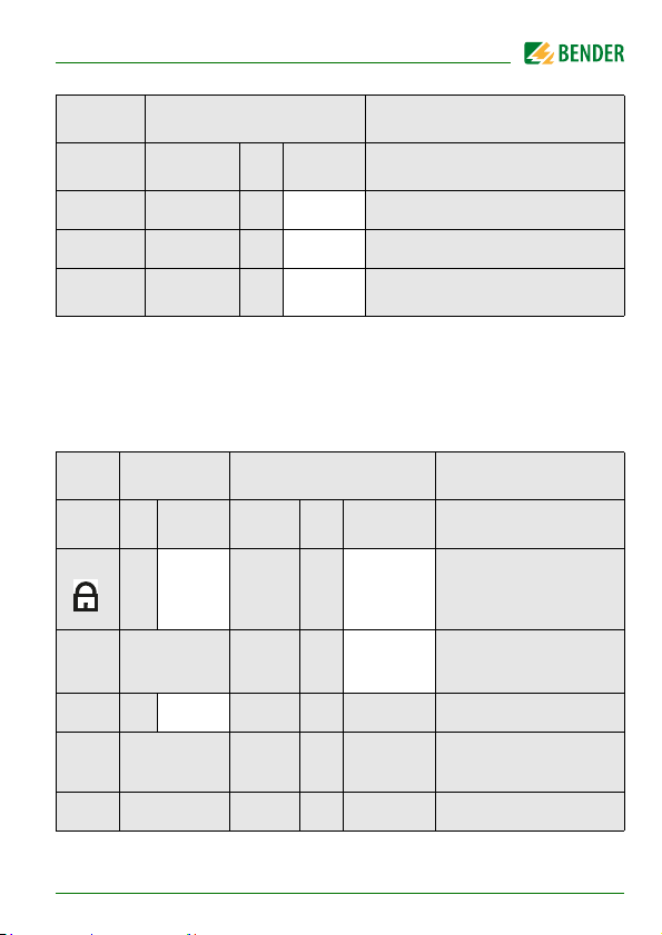
Display Einstellwert Beschreibung
Bereich FAC Ke
ton 0 … 99 0 s Ansprechverzögerung K1 und K2
toff 0 … 99 0 s Rückfallverzögerung K1 und K2
test OFF / 1 / 24 24 h Wiederholzeit Gerätetest
FAC = Werkseinstellung; Ke = Kundeneinstellungen
7.4 Menü „SEt“
Funktions-Konfiguration
Display Aktivierung Einstellwert Beschreibung
FAC Ke Bereich FA C
off 0 . . . 999
C
S.Ct on Gerätetest bei Gerätestart
FAC
SYS Nur für Bender Service
FAC = Werkseinstellung; Ke = Kundeneinstellungen
isoUG425_D00220_02_Q_DEEN / 05.2018
1 . . . 50 1μF
Ke
0
Passwort für
Parametereinstellung
Maximal zulässige Ableitkapazität C
Werkseinstellung (Factory
Setting) ausführen
e
13
Page 14
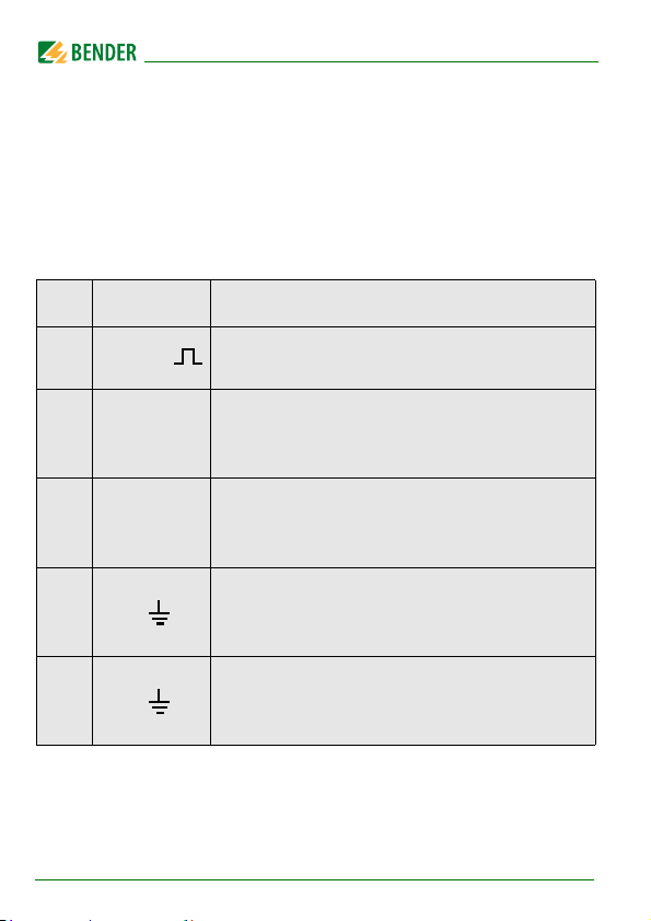
7.5 Messwertanzeige und Historienspeicher
Aus allen anderen Messwertanzeigen wird nach spätestens 5 min zur Standardanzeige (Isolationswiderstand) gewechselt. Das Pulssymbol kennzeichnet einen aktuellen Messwert. Fehlt dieses Symbol, läuft die Messung und es
wird der letzte gültige Messwert angezeigt. Die Symbole „<“ oder „>“ werden
zum Messwert eingeblendet, wenn ein Ansprechwert erreicht oder verletzt
bzw. der Messbereich unter- oder überschritten wurde.
HiS Display Beschreibung
R kΩ
Isolationswiderstand RF
1 kΩ ... 1 MΩ Auflösung 1 kΩ
Netznennspannung L+ - L- U
U L1 L2 =~ V
100 V
RMS
RMS
… 99,9 V
… 150 V
Auflösung 0,1 V
RMS
Auflösung 1 V
RMS
0 V
Netznennspannung L+ - L- U
U L1 L2 = V
0 VDC … 99,9 VDC Auflösung 0,1 V
100 VDC … 150 VDC Auflösung 1 V
Verlagerungsspannung L+ - PE U
± U L1 = V
0 VDC … 99,9VDC Auflösung 0,1 V
100 VDC … 150 VDC Auflösung 1 V
Verlagerungsspannung L- - PE U
± U L2 = V
: Messwert kann im Historienspeicher angezeigt werden.
14
0 VDC … 99,9VDC Auflösung 0,1 V
100 VDC … 150 VDC Auflösung 1 V
isoUG425_D00220_02_Q_DEEN / 05.2018
nRMS
nDC
L-e
L+e
RMS
RMS
DC
DC
DC
DC
DC
DC
Page 15

Technische Daten
( )* = Werkseinstellung
Isolationskoordination nach IEC 60664-1/IEC 60664-3
Definitionen:
Messkreis (IC1).....................................................................................................................................L1/+, L2/-
Versorgungskreis (IC2)................................................................................................................................A1, A2
Ausgangskreis (IC3) .............................................................................................................................. 11, 14, 24
Steuerkreis (IC4).............................................................................................................................E, KE, T/R, A, B
Bemessungsspannung ........................................................................................................................................... 400 V
Überspannungskategorie............................................................................................................................................. III
Bemessungs-Stoßspannung:
IC1/( IC2-4 ).....................................................................................................................................................6 kV
IC2/( IC3-4 ).....................................................................................................................................................4 kV
IC 3/IC4 ............................................................................................................................................................4 kV
Bemessungs-Isolationsspannung:
IC1/( IC2-4 ).................................................................................................................................................. 400 V
IC2/( IC3-4 ).................................................................................................................................................. 250 V
IC 3/IC4 .........................................................................................................................................................250 V
Verschmutzungsgrad .................................................................................................................................................... 3
Sichere Trennung (verstärkte Isolierung) zwischen:
IC1/( IC2-4 )...................................................................................................Überspannungskategorie III, 600 V
IC2/( IC3-4 )...................................................................................................Überspannungskategorie III, 300 V
IC 3/IC4 ..........................................................................................................Überspannungskategorie III, 300 V
Spannungsprüfungen (Stückprüfung) nach IEC 61010-1:
IC2/( IC3-4 )............................................................................................................................................AC 2,2 kV
IC2/IC4.....................................................................................................................................................AC 2,2 kV
Versorgungsspannung
Versorgungsspannung U
Toleranz von U
Frequenzbereich U
Eigenverbrauch .......................................................................................................................................≤ 3 W, ≤ 9 VA
....................................................................................... AC 100…240 V / DC 24…240 V
s
....................................................................................................................................... -30…+15 %
s
...................................................................................................................................... 47…63 Hz
s
isoUG425_D00220_02_Q_DEEN / 05.2018
15
Page 16

Überwachtes IT-System
Netznennspannung U
Toleranz von U
............................................................................................................................ DC 0…120 V
n
................................................................................................................................................... +20 %
n
Messkreis
Innenwiderstand R
Zulässige Netzableitkapazität C
...........................................................................................................................................≥ 115 kΩ
i
.........................................................................................................................≤ 50 μF
e
Ansprechwerte
Ansprechwert R
Ansprechwert R
Ansprechunsicherheit R
Hysterese R
Unterspannungserkennung U
Überspannungserkennung U
Ansprechunsicherheit U
Hysterese U
........................................................................................................................ 2…100 kΩ (50 kΩ)*
an1
.......................................................................................................................... 1…95 kΩ (25 kΩ)*
an2
................................................................................................. ± 15 %, mindestens ±2 kΩ
an
............................................................................................................................ 25 %, mindestens 1 kΩ
an
................................................................................................................................. 5 %, mindestens 1 V
DC
........................................................................................................ 8…143 kV (off)*
DC
.......................................................................................................8,1…144 kV (off)*
DC
................................................................................................. ± 5 %, mindestens ± 0,5 V
DC
Zeitverhalten
Ansprechzeit t
bei RF = 0,5 x Ran und Ce=1 μF nach IEC 61557-8 ................................................................... ≤ 1 s
an
Anlaufverzögerung t ............................................................................................................................. 0…10 s (0 s)*
Ansprechverzögerung t
Rückfallverzögerung t
..................................................................................................................... 0…99 s (0 s)*
on
........................................................................................................................ 0…99 s (0 s)*
off
Anzeigen, Speicher
Anzeige........................................................................................................ LC-Display, multifunktional, unbeleuchtet
Anzeigebereich Messwert Is olationswiderstand (R
Betriebsmessunsicherheit.................................................................................................. ± 15 %, m inde stens ±2 kΩ
Anzeigebereich Messwert Netznennspannung (U
Betriebsmessunsicherheit U
Betriebsmessunsicherheit U
........................................................................................... ± 5 %, mindestens ± 0,5 V
DC
........................................................................................ ± 5 %, mindestens ± 1,5 V
RMS
).............................................................................. 1 kΩ…1 MΩ
F
) ..................... 0…150 V (RF =∞ : 300 VP; RF = 0 kΩ : 150 VP)
n
Passwort ..................................................................................................................................... off / 0…999 (0, off)*
Fehlerspeicher Alarmmeldungen .................................................................................................................. on / (off)*
Schnittstelle
Schnittstelle/Protokoll ......................................................................................... RS-485/BMS, Modbus RTU, isoDat a
16
isoUG425_D00220_02_Q_DEEN / 05.2018
Page 17

Baudrate ............................................................BMS (9,6 kBit/s), Modbus RTU (einstellbar), isoData (115,2 kBits/s)
Leitungslänge (9,6 kBits/s) ........................................................................................................................... ≤ 1200 m
Leitung: paarweise verdrillt, Schirm einseitig an PE ...................................................................... min. J-Y(St)Y 2x0.6
Abschlusswiderstand ............................................................................................ 120 Ω (0,25 W), intern, zuschaltbar
Geräteadresse, BMS-Bus, Modbus RTU ..................................................................................................... 3…90 (3)*
Schaltglieder
Schaltglieder ................................................................................................ 2 x 1 Schließer, gemeinsame Klemme 11
Arbeitsweise ................................................................................................... Ruhestrom/Arbeitsstrom (Ruhestrom)*
Elektrische Lebensdauer bei Bemessungsbedingungen ............................................................... 10000 Schaltspiele
Kontaktdaten nach IEC 60947-5-1:
Gebrauchskategorie ............................................................ AC-12..........AC-14 ..........DC-12 ..........DC-12 .......DC-12
Bemessungsbetriebsspannung ........................................... 230 V...........230 V .............24 V .......... 110 V ........ 220 V
Bemessungsbetriebsstrom ...................................................... 5 A...............2 A ...............1 A ........... 0,2 A ......... 0,1 A
Minimale Kontaktbelastbarkeit ............................................................................................. 1 mA bei AC / DC ≥ 10 V
Umwelt/EMV
EMV ......................................................................................................................................................... IEC 61326-2-4
Umgebungstemperaturen:
Betrieb ..................................................................................................................................................... -40…+70 ºC
Transport ................................................................................................................................................. -40…+85 ºC
Lagerung ................................................................................................................................................. -40…+70 ºC
Klimaklassen nach IEC 60721
Ortsfester Einsatz (IEC 60721-3-3) ................................................................... 3K7 (ohne Betauung und Eisbildung)
Transport (IEC 60721-3-2) ................................................................................ 2K4 (ohne Betauung und Eisbildung)
Langzeitlagerung (IEC 60721-3-1) ................................................................... 1K5 (ohne Betauung und Eisbildung)
Mechanische Beanspruchung nach IEC 60721
Ortsfester Einsatz (IEC 60721-3-3) ........................................................................................................................ 3M4
Transport (IEC 60721-3-2) ..................................................................................................................................... 2M2
Langzeitlagerung (IEC 60721-3-1) ........................................................................................................................ 1M3
Anschluss
Anschlussart...............................................................................................................................................Federklemme
Nennstrom ............................................................................................................................................................≤ 10 A
Leitergrößen ................................................................................................................................................. AWG 24-14
isoUG425_D00220_02_Q_DEEN / 05.2018
17
Page 18
Abisolierlänge .......................................................................................................................................................10 mm
Starr .........................................................................................................................................................0,2…2,5 mm
Flexibel ohne Aderendhülse.................................................................................................................0,75…2,5 mm
flexibel mit Aderendhülse mit/ohne Kunststoffhülse..........................................................................0,25…2,5 mm
Mehrleiter flexibel mit TWIN Aderendhülse mit Kunststoffhülse ........................................................0,5…1,5 mm
Öffnungskraft ........................................................................................................................................................... 50 N
Testöffnung, Durchmesser ................................................................................................................................. 2,1 mm
Sonstiges
Betriebsart ................................................................................................................................................. Dauerbetrieb
Einbaulage .................................................................................... Kühlschlitze müssen senkrecht durchlüftet werden
Schutzart Einbauten (DIN EN 60529) ..................................................................................................................... IP30
Schutzart Klemmen (DIN EN 60529) ...................................................................................................................... IP20
Gehäusematerial ....................................................................................................................................... Polycarbonat
Schnellbefestigung auf Hutprofilschiene ...................................................................................................... IEC 60715
Schraubbefestigung ................................................................................................................ 2 x M4 mit Montageclip
Gewicht ...............................................................................................................................................................≤ 150 g
Normen, Zulassungen und Zertifizierungen
Das ISOMETER® wurde unter Beachtung folgender Normen entwickelt:
DIN EN 50155
2
2
2
2
18
isoUG425_D00220_02_Q_DEEN / 05.2018
Page 19
ISOMETER® isoUG425
EN
Insulation monitoring device for unearthed
DC systems (IT systems) up to 120 V
Software version: D476 V2.xx
This operating manual is designed for electrically skilled persons working in
electrical engineering and electronics! It does not replace the operating manual. Make sure that the personnel has read this manual and understood all
instructions relating to safety.
The manual can be found at:
www.bender.de/en/service-support/downloads
1. Intended use
The ISOMETER® monitors the asymmetrical insulation resistance RF of unearthed DC main circuits (IT systems) with nominal system voltages of
DC 12. . .120 V. The maximum permissible system leakage capacitance C
50 uF
In the case of an insulation fault on a power conductor, the
measured residual voltage is evaluated to determine the
insulation resistance R
can be detected using the passive measurement method
employed in this ISOMETER®. Equally large insulation faults
between the positive and negative power conductors to
earth (i.e. symmetrical faults) are not detected .
. Only asymmetrical insulation faults
F
is
e
In the event of an alarm message, the insulation fault should
be eliminated as quickly as possible.
isoUG425_D00220_02_Q_DEEN / 05.2018
19
Page 20
If the ISOMETER® is installed inside a control cabinet, the
insulation fault message must be audible and/or visible to
attract attention.
2. Safety information
Installation, connection and commissioning of electrical equipment shall only
be carried out by qualified electricians. Particular attention must be paid to:
The current safety regulations, in particular DIN EN 50110
Enclosed sheet "Important safety instructions for Bender Products".
3. Functional description
The ISOMETER® measures the unsymmetrical insulation resistance RF between the network being monitored (L+, L-) and earth (PE).
The effective and DC values of the nominal system voltage U
L- as well as the residual voltages U
ween L- and earth) are also measured. The detected fault or the faulty conduc-
(between L+ and earth) and U
L+e
tor can be assigned, via the menu, to an alarm relay. If the values of R
exceed the thresholds set in the "AL" menu, this will be indicated by the LEDs,
and relays "K1" and "K2" according to the message assignment settings in the
"out" menu. In addition, the operation of the relay (n.o./n.c) can be set and the
fault memory "M" activated. If the values of R
(response value plus hysteresis) without interruption for a period no longer
, then the alarm relays return to their initial position and the alarm
than t
off
or Un exceed their release value
F
LEDs "AL1"/"AL2" are turned off. With the fault memory activated, the alarm
relays remain in alarm state and the LEDs light until the reset button "R"
pressed or until the supply voltage U
has been interrupted.
s
The device function can be tested using the test button "T". Parameters are
assigned to the device via the LCD and the control buttons on the front panel;
this function can be password-protected. Parameterisation is also possible via
the BMS bus, for example by using the BMS Ethernet gateway (COM460IP) or
the Modbus RTU.
between L+ and
n
L-e
or Un
F
(bet-
20
isoUG425_D00220_02_Q_DEEN / 05.2018
Page 21
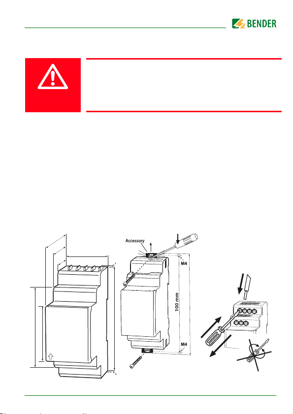
4. Installation and connection
Risk of electric shock!
Avoid any physical contact with active conductors and
ensure compliance with the regulations for working on
DANGER
electrical installations
Consider a minimum distance to adjacent devices:
sides 0 mm; above and below 20 mm.
DIN rail mounting
Snap the mounting clip at the rear of the device onto the DIN rail so that it sits
so that it sits securely
Screw mounting
Use a tool to position the rear mounting clips (a second mounting clip is required, see ordering information in the manual) so that it protrudes over the
enclosure. Fix the device with two M4 screws (see below).
.
74.5
47.5
36 mm
31.1
67.5
45
isoUG425_D00220_02_Q_DEEN / 05.2018
2
93 mm
2
Click
2
107 mm
1
3
21
Page 22
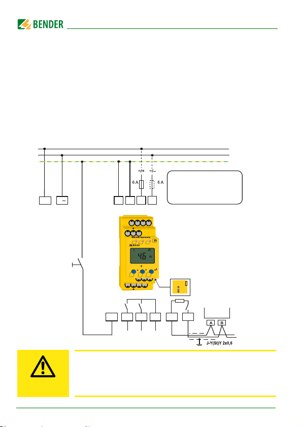
Wiring diagram
L+
KE
14 24 11
K1 K2
E
T/R
Test/Reset
L
COM460IP
RS-485
L+
L-
PE
A
B
R
ON
TR
MENU
AL1 AL2
k
<
k
ISOMETER
isoUG425
L+ L-
EKEA1A2
14 24
11
T/R
A
B
R
on
off
U
S
A1 A2
The supply voltage Us applied
to A1/A2 can be provided by the
system voltage (L +/L-) when the
system voltage is ≥ 24V DC. Otherwise
a separate power supply is needed.
The supply voltage US applied to A1 and A2 can be provided by the system
voltage L+ and L- only when the supply voltage is ≥ 24 V DC. Otherwise a separate power supply is required. Connect terminals "A1" and "A2" to the supply voltage U
protected against short circuit by means of a protective device (a 6 A fuse is
recommended). Devices for protection against short-circuit in conformity
with IEC 0100-430 for the connection of terminals L+/L- to the IT system to be
monitored can be omitted if the wiring is carried out in such a manner as to
reduce the risk of a short-circuit to a minimum.
CAUTION
22
according to IEC 60364-4-43, i.e. the connections are to be
s
isoUG425_D00220_02_Q_DEEN / 05.2018
Only one ISOMETER® may be controlled via an external Test/
Reset button. A galvanic parallel connection of several test or
reset inputs for testing multiple insulation monitoring
devices is not allowed.
Page 23
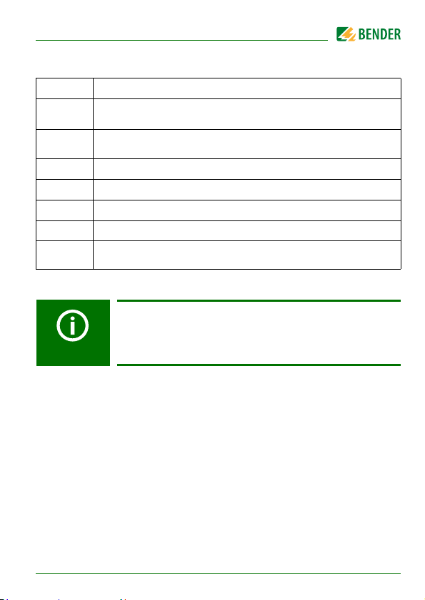
Wiring diagram legend
Terminal Connections
A1, A2
E, KE
L+, L– Connection to the DC system to be monitored
11, 14
11, 24
Connection to the supply voltage Us via fuse (line protection). If supplied from an IT system, both lines have to be protected by a fuse.
Connect each terminal separately to PE.
The same wire cross section as for "A1", "A2" is to be used.
T/R Connection to the external combined test and reset button
Alarm relay "K1" terminal
Alarm relay "K2" terminal
RS-485 communication interface with switchable termination
A, B
resistor
* For UL applications:
Only use 60/75°C copper lines!
For UL and CSA applications, it is mandatory to use fuses
rated over 5 A to protect the supply voltage U
.
s
isoUG425_D00220_02_Q_DEEN / 05.2018
23
Page 24
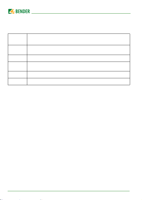
5. Error codes
If a device error occurs, the following error codes are displayed:
Error
code
E.01
E.02 The polarity of the DC system to be monitored is false.
E.05
E.08 A calibration error was detected during the device test
E.xx Device error - Contact Bender Service
Meaning
The connection between terminals "E" or "KE" and earth is interrupted
Measurement error/invalid calibration for the current software
version
24
isoUG425_D00220_02_Q_DEEN / 05.2018
Page 25
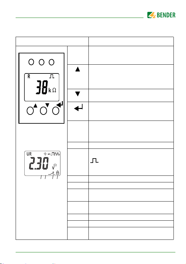
6. User display elements
ON AL1 AL2
T
MENU
R
+
test onoff MAdr
L1L2
C
<
>
s
kM %
Fµ
{
{
{
{
4
Hz
{
: Disturbance-free measured value
updates
Device front panel/display Function
ON
AL1
AL2
T
R
green - On
yellow - Alarm
yellow - Alarm
Up button
Test button (press for > 1.5 s)
The display elements can be seen by
holding down the test button.
Down button
Reset button (press for > 1.5 s)
ENTER
Assignment according
to table on page 28
1
10
9
isoUG425_D00220_02_Q_DEEN / 05.2018
3
2
{
8
567
MENU
MENU button (press for > 1.5 s)
1U : Nominal system voltage U
R : Insulation resistance R
C : System leakage capacitance C
2 Line being monitored
3= : Voltage type DC
=~ : Voltage type RMS
4 Measured value and unit
5 Password protection enabled
6 In menu mode, the operation of the
respective alarm relay is indicated.
7 Communication interface
Measured value: isoData operation
8 Error memory is enabled.
9 Mode symbol
10 Identifier for response values and
response-value violation
F
n
e
25
Page 26
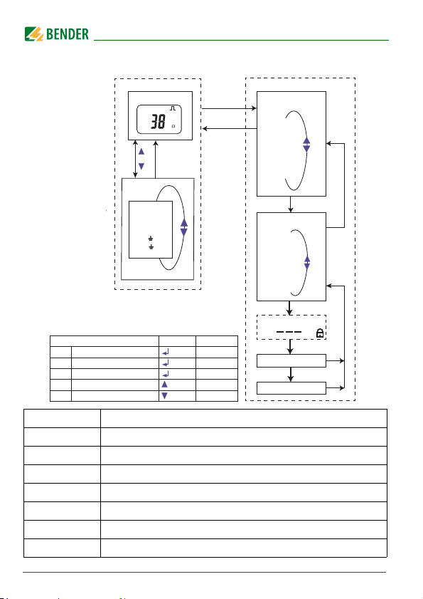
7. Menu overview
Measurement display
Standard display
R
k
Enter
or
t > 5 Min.
Menu
Esc
Menu selection
AL
out
t
SEt
InF
HiS
ESC
R [ kΩ ]
U L1 L2 [ V
U L1 L2 [ V
UL1 [ V
UL2 [ V
Function Button Conrm
Enter
Select, acknowledge input
Menu
Call menu
Esc
Exit menu item
Test
Start device test
Reset
Clear fault menu
]
RMS
]
DC
]
DC
]
DC
/ MENU Kurz
/ MENU
/ MENU
/ T
/ R
> 1.5 s
> 1.5 s
> 1.5 s
> 1.5 s
Parameter selection
Menu item Adjustable parameter
AL
out
SEt
InF
HiS
ESC
26
Response value query and setting
Configure, fault memory, alarm relay and interface
Set delay times and self-test cycles
t
Set device control parameters
Query software version
Query and delete memory history
Go to next higher menu level
isoUG425_D00220_02_Q_DEEN / 05.2018
Enter
P
1
. . .
P
n
ESC
Enter
Optional Password
Enter
Edit parameters
Enter
Save parameters
Esc
Esc
Page 27
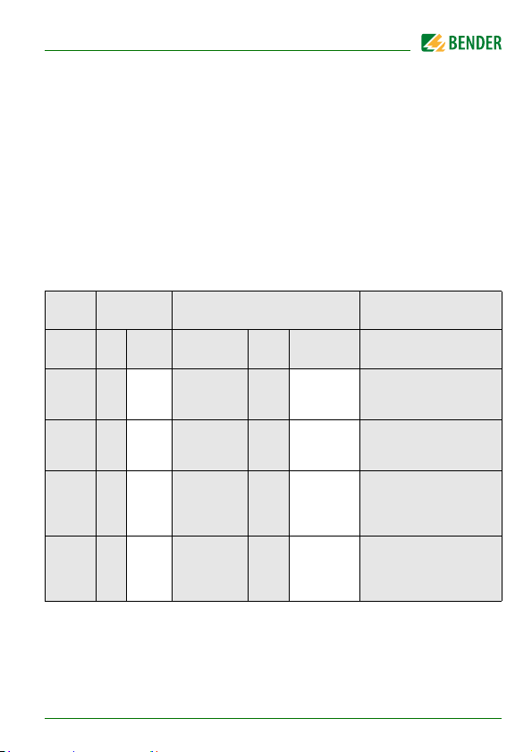
7.1 "AL" menu
Response settings
The response value menu "AL" contains the parameters "R1" and "R2", which
are used to monitor the insulation resistance R
greater than that for R2. If the value of R
lues of R1 or R2, then an alarm message is triggered. The alarm is cleared if R
exceeds the values of R1 or R2 plus the hysteresis value (see table below).
The parameters "U <" and "U >" that monitor the nominal system voltage U
can also be activitated or deactivated in the "AL" menu. The maximum undervoltage value is limited by the overvoltage value.
Display Activation Setting Description
. The setting for R1 must be
F
reaches or falls below the active va-
F
F
n
FAC
R1 < R2 … 100 50 kΩ
R2 < 1 … R1 25 kΩ
U < off 8 … U> 8 V
U > off
FAC = Factory setting; Cs = User setting
isoUG425_D00220_02_Q_DEEN / 05.2018
Cs
Bereich FAC
U< … 144
Cs
140 V
Pre-alarm value R
Hys. = 25 %/min. 1 kΩ
Alarm value R
Hys. = 25 %/min. 1 kΩ
Alarm value
Undervoltage DC
Hys . = 5 %/min. 1 V
Alarm value
Overvoltage DC
Hys. = 5 %/min. 1 V
an1
an2
27
Page 28
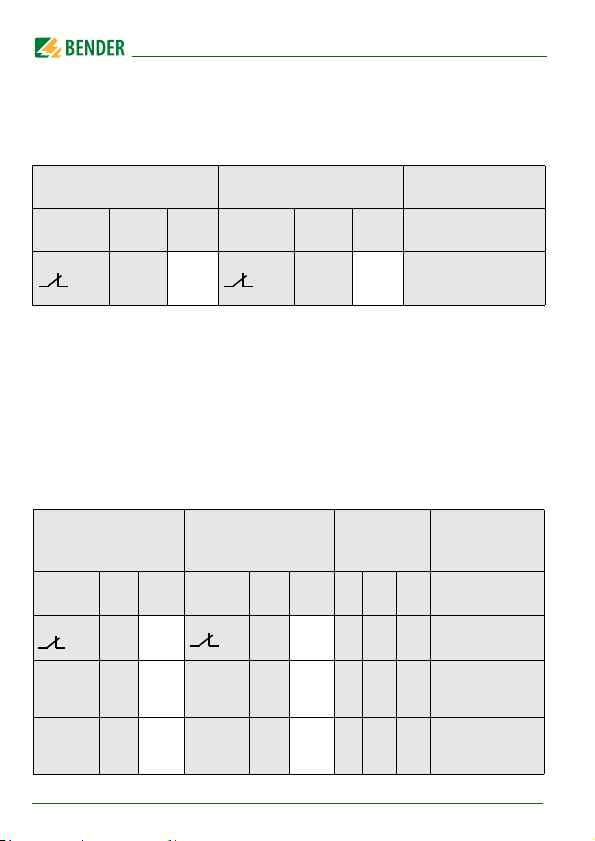
7.2 "out" menu
1
2
1
Err
2
Configuration of relay operation
Relay K1 Relay K2 Description
Display FAC Cs Display FAC Cs
n.c. n.c.
FAC = Factory setting; Cs = User setting
Relay operation
n.c / n.o.
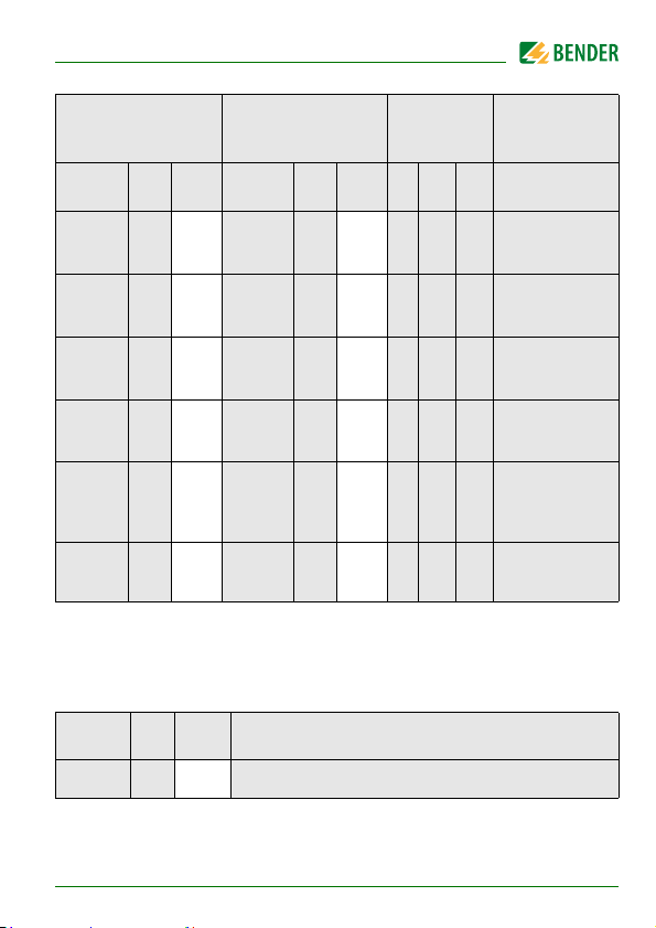
Relay signaling assignment "r1" and "r2" and LED assignment
When set to "on", the individual messages/alarms are assigned or mapped to
each relay. The LED display is directly associated with the messages and is not
related to the relay. In the event of an unsymmetrical insulation fault, only the
message corresponding to the assigned conductor (L+ or L-) will be displayed.
K1 "r1" K2 "r2"
Display
r1
+R1 < Ω
r1
- R1 < Ω
FAC Cs
off on
on
on
28
Display
r2
+R1 < Ω
r2
-R1 < Ω
LEDs
FAC Cs
ON AL1 AL2
off
off
isoUG425_D00220_02_Q_DEEN / 05.2018
Message
description
Device Error E.xx
Pre-alarm R1
Error R
Pre-alarm R1
Error RF an L-
on L+
F
Page 29
K1 "r1" K2 "r2"
LEDs
Message
description
Display
r1
+R2 < Ω
r1
-R2 < Ω
r1
U < V
r1
U > V
r1
test
r1
S.AL
FAC = Factory setting; Cs = User setting
FAC Cs
off
off
off
off
off
off
: LED off : LED blinking : LED on
Display
r2
+R2 <Ω
r2
-R2 < Ω
r2
U < V
r2
U > V
r2
test
r2
S.AL
FAC Cs
on
on
on
on
off
off
ON AL1 AL2
Alarm R2
Error RF on L+
Alarm R2
Error RF on L-
Alarm U
Undervoltage
Alarm U
Overvoltage
Device test
manually
started
Device start with
alarm
Fault memory configuration
Display FAC Cs Description
M off Memory function for alarm messages (Fault memory)
FAC = Factory setting; Cs = User setting
nDC
nDC
isoUG425_D00220_02_Q_DEEN / 05.2018
29
Page 30
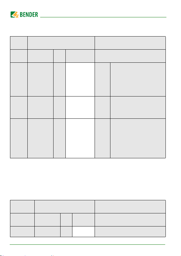
Interface configuration
Display Setting Description
Range FA C Cs
Adr = 0
BMS disabled as well as
Adr 0 / 3 … 90 3 ( )
Bus-
Modbus; Isodata enabled
Addr.
with continuous data
output (115k2, 8E1)
--- /
Adr 1
1.2k … 115k
Adr 2
FAC = Factory setting; Cs = User setting
( ) = Customer setting not changed by factory setting.
8E1
8o1
8n1
“---“ ( )
8E1 ( )
“---“ : BMS bus (9k6, 7E1)
Baud
“1.2k“ … “115k“ -->
rate
Modbus (variable, var.)
8E1 - 8 data bits
even parity, 1 stop bit
8o1 - 8 data bits
odd Parity, 1 stop bit
8n1 - 8 data bits
no parity, 1 stop bit
Modbus
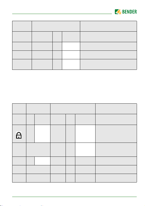
7.3 “t“ menu
Configuring time settings
Display Setting Description
Range FA C Cs
t 0 … 10 0 s Device start up time
30
isoUG425_D00220_02_Q_DEEN / 05.2018
Page 31
Display Setting Description
Range FAC Cs
ton 0 … 99 0 s Response delay K1 und K2
toff 0 … 99 0 s Release delay K1 und K2
OFF / 1 / 24
test
FAC = Factory setting; Cs = User setting
24 h Repeat device test
7.4 “SEt“ menu
Function configuration
Display Activation Setting Description
FAC Cs Bereich FAC
off 0 . . . 999
C
S.Ct on Device test at device start
FAC Run factory settings
SYS For Bender Service only
FAC = Factory setting; Cs = User setting
isoUG425_D00220_02_Q_DEEN / 05.2018
1 . . . 50 1μF
Cs
0
Password for parameter
setting
Maximam permissible
leakage capacitance C
e
31
Page 32
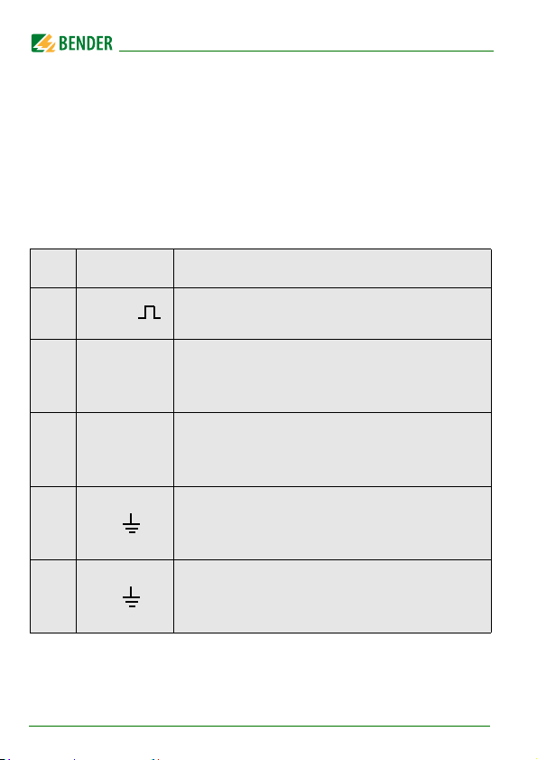
7.5 Measured values and history memory
Only RF is permanently displayed (standard display). For all other measurements, the display returns to the standard display after at least 5 min. The pulse symbol indicates a current reading. In the absence of this symbol, the
measurement is still read and only the last valid measured value is displayed.
The symbol „<“ or „>“ is displayed with the measured value when a response
value has been reached or exceeded, or if the measuring range is outside the
set parameters.
HiS Display Description
R kΩ
Insulation resistance RF
1 kΩ … 1 MΩ Resolution 1 kΩ
Nominal system voltage L+ - L- U
U L1 L2 =~V
100 V
RMS
RMS
… 99.9 V
… 150 V
Resolution 0.1 V
RMS
Resolution 1 V
RMS
0 V
Nominal system voltage L+ - L- U
U L1 L2 =V
0 VDC … 99.9 VDC Resolution 0.1 VDC
100 VDC … 150 VDC Resolution 1 V
Residual voltage L+ - PE U
… 99.9VDC Resolution 0.1 V
± U L1 = V
0 V
DC
100 VDC … 150 VDC Resolution 1 V
Residual voltage L- - PE U
± U L2 = V
: Measured value can be displayed in the history memory.
32
0 VDC … 99.9VDC Resolution 0.1 V
100 VDC … 150 VDC Resolution 1 V
isoUG425_D00220_02_Q_DEEN / 05.2018
L+e
L-e
nRMS
RMS
RMS
nDC
DC
DC
DC
DC
DC
Page 33

Technical data
( )* = Factory setting
Insulation coordination acc. to IEC 60664-1/IEC 60664-3
Definitions:
Measuring circuit (IC1).........................................................................................................................L1/+, L2/-
Supply circuit (IC2)......................................................................................................................................A1, A2
Output circuit(IC3)................................................................................................................................. 11, 14, 24
Control circuit (IC4) ........................................................................................................................E, KE, T/R, A, B
Rated voltage.......................................................................................................................................................... 400 V
Overvoltage category.................................................................................................................................................... III
Rated impulse voltage:
IC1/( IC2-4 ).....................................................................................................................................................6 kV
IC2/( IC3-4 ).....................................................................................................................................................4 kV
IC 3/IC4 ............................................................................................................................................................4 kV
Rated insulated voltage:
IC1/( IC2-4 ).................................................................................................................................................. 400 V
IC2/( IC3-4 ).................................................................................................................................................. 250 V
IC 3/IC4 .........................................................................................................................................................250 V
Pollution ........................................................................................................................................................................ 3
Protective separation (reinforced insulation) between:
IC1/( IC2-4 )............................................................................................................. Overvoltage category, 600 V
IC2/( IC3-4 )............................................................................................................. Overvoltage category, 300 V
IC 3/IC4 ....................................................................................................................Overvoltage category, 300 V
Voltage test (routine test) according to IEC 61010-1:
IC2/( IC3-4 )............................................................................................................................................AC 2.2 kV
IC 3/IC4....................................................................................................................................................AC 2.2 kV
Supply voltage
Supply voltage U
Tolerance of U
Frequency range U
Power consumption ............................................................................................................................... ≤ 3 W, ≤ 9 VA
...................................................................................................... AC 100…240 V/DC 24…240 V
s
........................................................................................................................................ -30…+15 %
s
...................................................................................................................................... 47…63 Hz
s
isoUG425_D00220_02_Q_DEEN / 05.2018
33
Page 34

IT system being monitored
Nominal system voltage U
Tolerance of U
................................................................................................................... DC 12…120 V
n
........................................................................................................................................................ 20%
n
Measuring circuit
Internal resistance R
Permissible leakage capacitance C
.........................................................................................................................................≥ 115 kΩ
i
................................................................................................................... ≤ 50 μF
e
Response values
Response value R
Response value R
Operating uncertainty R
Hysteresis R
Undervoltage detection U
Overvoltage detection U
Operating uncertainty U
Hysteresis U
...................................................................................................................... 2…100 kΩ (50 kΩ)*
an1
........................................................................................................................ 1…95 kΩ (25 kΩ)*
an2
......................................................................................................... ± 15 %, at least ±2 kΩ
an
.................................................................................................................................... 25 %, at least 1 kΩ
an
....................................................................................................................................... 5 %, at least 1 V
DC
................................................................................................................ 8…143 V (off)*
DC
................................................................................................................ 8.1…144 V (off)*
DC
........................................................................................................ ± 5 %, at least ± 0.5 V
DC
Time response
Response time t
Start-up delay t ..................................................................................................................................... 0…10 s (0 s)*
Response delay t
Delay on release t
at RF= 0.5 x Ran and Ce=1 μF acc. to IEC 61557-8 ................................................................ ≤ 1 s
an
................................................................................................................................ 0…99 s (0 s)*
on
............................................................................................................................... 0…99 s (0 s)*
off
Displays, memory
Display..................................................................................................... LC display, multi-functional, not illuminated
Display range measured value insulation resistance (R
Operating uncertainty............................................................................................................... ± 15 %, at least ±2 kΩ
Display range measured value nominal system voltage (U
Operating uncertainty U
Operating uncertainty U
Password ....................................................................................................................................... off/0…999 (0, off)*
........................................................................................................ ± 5 %, at least ± 0.5 V
DC
..................................................................................................... ± 5 %, at least ± 1.5 V
RMS
)........................................................................ 1 kΩ…1 MΩ
F
)....... 0… 150 V (RF =∞ : 300 VP; RF = 0 kΩ : 150 VP)
n
Fault memory alarm message........................................................................................................................ on / (off)*
34
isoUG425_D00220_02_Q_DEEN / 05.2018
Page 35

Interface
Interface/protocol ................................................................................................ RS-485 / BMS, Modbus RTU, isoData
Baud rate .......................................................... BMS (9.6 kBit/s), Modbus RTU (adjustable), isoData (115.2 kBits/s)
Cable length (9.6 kBits/s ................................................................................................................................ ≤ 1200 m
Cable: twisted pair, shield connected to PE ................................................................................... min. J-Y(St)Y 2x0.6
Terminating resistor.................................................................................. 120 Ω (0.25 W), internal, can be connected
Device address, BMS bus, Modbus RTU ..................................................................................................... 3…90 (3)*
Switching elements
Switching elements ....................................................................................... 2 x 1 NO contacts, common terminal 11
Operating principle ............................................................................ N/C operation/N/O operation (N/C operation)*
Electrical endurance, number of cycles ................................................................................................................10 000
Contact data acc. to IEC 60947-5-1:
Utilisation category.............................................................. AC-12..........AC-14 ......... DC-12 ......... DC-12 ....... DC-12
Rated operational voltage......................................................230 V.......... 230 V............ 24 V ..........110 V ........ 220 V
Rated operational current ........................................................ 5 A...............2 A .............. 1 A ........... 0.2 A ......... 0.1 A
Minimum contact rating............................................................................................................ 1 mA at AC/DC ≥ 10 V
Environment/EMC
EMC .......................................................................................................................................................... IEC 61326-2-4
Ambient temperatures:
Operation.................................................................................................................................................. -40…+70 °C
Transport ................................................................................................................................................. -40…+85 °C
Storage ..................................................................................................................................................... -40…+70 °C
Climatic class acc. to IEC 60721
Stationary use (IEC 60721-3-3)........................................................................ 3K7 (without condensation and icing)
Transport (IEC 60721-3-2) ............................................................................... 2K4 (without condensation and icing)
Long-time storage (IEC 60721-3-1)................................................................ 1K5 (without condensation and icing)
Classification of mechanical conditions acc. to IEC 60721
Stationary use (IEC 60721-3-3) ...............................................................................................................................3M4
Transport (IEC 60721-3-2) ..................................................................................................................................... 2M2
Long-term storage (IEC 60721-3-1) ...................................................................................................................... 1M3
isoUG425_D00220_02_Q_DEEN / 05.2018
35
Page 36

Connection
Connection type................................................................................................................................Push-wire terminal
Nominal current....................................................................................................................................................≤ 10 A
Conductor sizes .............................................................................................................................................AWG 24-14
Stripping length....................................................................................................................................................10 mm
Rigid.........................................................................................................................................................0.2…2.5 mm²
Flexible without ferrules ....................................................................................................................... 0.75…2.5 mm²
flexible with ferrules, with/without plastic collar................................................................................ 0.25…2.5 mm²
Multiple conductor, flexible withTWIN ferrule with plastic sleeve.......................................................0.5…1.5 mm²
Opening force........................................................................................................................................................... 50 N
Test opening, diameter....................................................................................................................................... 2.1 mm
Other
Operating mode ........................................................................................................................... Continuous operation
Mounting..................................................................................................... Cooling slots must be ventilated vertically
Degree of protection, built-in components (DIN EN 60529) ................................................................................. IP30
Degree of protection, terminals (DIN EN 60529) ................................................................................................... IP20
Enclosure material ....................................................................................................................................Polycarbonate
DIN rail mounting acc. to................................................................................................................................. IEC 60715
Screw fixing ......................................................................................................................... 2 x M4 with mounting clip
Weight.................................................................................................................................................................≤ 150 g
36
isoUG425_D00220_02_Q_DEEN / 05.2018
Page 37
Standards, approvals and certifications
The ISOMETER® has been developed in compliance with the following standards:
DIN EN 50155
isoUG425_D00220_02_Q_DEEN / 05.2018
37
Page 38

38
isoUG425_D00220_02_Q_DEEN / 05.2018
Page 39

isoUG425_D00220_02_Q_DEEN / 05.201840isoUG425_D00220_02_Q_DEEN / 05.2018
39
Page 40
Bender GmbH & Co. KG
Londorfer Str. 65 • 35305 Grünberg • Germany
Postfach 1161 • 35301 Grünberg • Germany
Tel.: +49 6401 807-0 Fax: +49 6401 807-259
E-Mail: [email protected]
Web: http://www.bender.de
BENDER Group
 Loading...