

Page 1
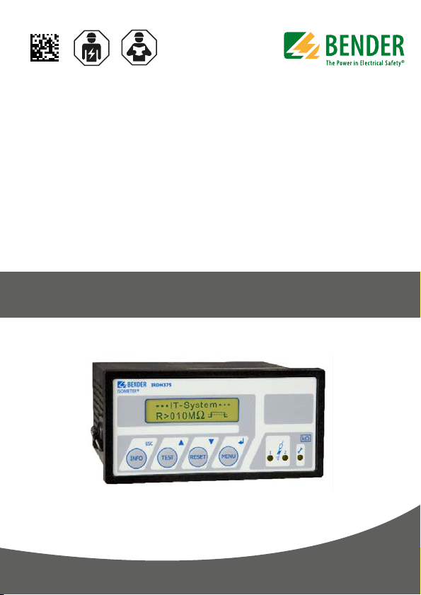
ISOMETER® IRDH375
Insulation monitoring device for
IT AC systems with galvanically connected
rectifiers and converters
and for IT DC systems
IRDH375: Software-Version D0183 V1.8
IRDH375B: Software-Version D0184 V1.8
IRDH375B
IRDH375_D00124_05_M_XXEN/01.2020
Manual EN
Page 2

Table of Contents
1. Important information .................................................................................... 7
1.1 How to use this manual ................................................................................. 7
1.2 Technical support: service and support ................................................... 8
1.2.1 First level support ............................................................................................. 8
1.2.2 Repair service ..................................................................................................... 8
1.2.3 Field service ........................................................................................................ 9
1.3 Training courses ............................................................................................. 10
1.4 Delivery conditions ....................................................................................... 10
1.5 Inspection, transport and storage ........................................................... 10
1.6 Warranty and liability ................................................................................... 11
1.7 Disposal ............................................................................................................ 12
2. Safety instructions ......................................................................................... 13
2.1 General safety instructions ........................................................................ 13
2.2 Work activities on electrical installations ............................................. 13
2.3 Device-specific safety information ......................................................... 14
2.4 Intended use ................................................................................................... 16
2.5 Directions for installation ........................................................................... 17
3. Function ........................................................................................................... 19
3.1 Common characteristics (IRDH375 and IRDH375B) .......................... 19
3.2 Additional characteristics IRDH375B ...................................................... 20
3.3 Product description ...................................................................................... 20
3.4 Function ............................................................................................................ 21
3.4.1 Self test .............................................................................................................. 22
3.4.2 Relay K3: device fault alarm and EDS common message ............... 23
3.5 Additional functions IRDH375B ............................................................... 25
IRDH375_D00124_05_M_XXEN/01.2020
3
Page 3

Table of Contents
4. Commissioning flow chart (threepart) ...................................................... 30
5. Connection ..................................................................................................... 33
5.1 Wiring ................................................................................................................ 33
5.2 Wiring diagrams with coupling devices ................................................ 37
5.2.1 Connection with AGH150W-4 .................................................................. 37
5.2.2 Connection with AGH520S ........................................................................ 39
5.2.3 Connection with AGH204S-4 .................................................................... 40
6. Operation and setting .................................................................................. 42
6.1 Operating features and displays IRDH375(B) ...................................... 42
6.1.1 Display in the standard mode ................................................................... 43
6.1.2 Display in the menu mode ......................................................................... 44
6.1.3 Function keys .................................................................................................. 44
6.2 Menu structure and menu mode ............................................................ 47
6.2.1 Diagram menu structure ............................................................................ 49
6.3 Menu HISTORY INFO (IRDH375B) ............................................................ 50
6.3.1 Diagram HISTORY INFO (IRDH375B) ....................................................... 51
6.4 Menu ISO SETUP: Setting of the basic ISOMETER® functions ........ 52
6.4.1 Response values Alarm 1 and Alarm 2 ................................................... 52
6.4.2 Operating principle of the alarm relays ................................................ 52
6.4.3 Memory setting (on/off) .............................................................................. 55
6.4.4 Current output for external measuring instruments
(IRDH375B) ....................................................................................................... 55
6.5 Menu ISO ADVANCED: Setting of the extended functions ........... 56
6.5.1 External coupling devices (AGH: no) ...................................................... 56
6.5.2 Adaptation to the system leakage capacitance
(Cemax : 150 μF) ............................................................................................. 57
6.5.3 Changing the measuring principle from AMP to DC
(Measure: AMP) .............................................................................................. 57
6.5.4 Setting the repetition time for automatic self tests
(Autotest: 24h) ................................................................................................ 57
6.5.5 Setting the real-time clock (Clock) (IRDH375B) .................................. 58
4
IRDH375_D00124_05_M_XXEN/01.2020
Page 4

Table of Contents
6.5.6 Setting the date (Date) (IRDH375B) ........................................................ 58
6.5.7 Specifying the starting time of the automatic self test (Test)
(IRDH375B) ....................................................................................................... 58
6.5.8 Diagram ISO ADVANCED ............................................................................ 59
6.6 Menu COM SETUP: Setting the BMS interface .................................... 60
6.6.1 Bus address „Addr:“ (IRDH375B) ............................................................. 60
6.6.2 ISOnet function (IRDH375B) ...................................................................... 60
6.6.3 ISO monitor (IRDH375B) ............................................................................. 61
6.6.4 Diagram COM SETUP (IRDH375B) ........................................................... 62
6.7 Menu PASSWORD ......................................................................................... 63
6.7.1 Activating and setting the password ..................................................... 63
6.7.2 Diagram PASSWORD .................................................................................... 64
6.8 Menu LANGUAGE .......................................................................................... 65
6.8.1 Setting the national language .................................................................. 65
6.8.2 Diagram Language ....................................................................................... 66
6.9 Menu SERVICE ................................................................................................ 66
6.10 Parameterization via Internet ................................................................... 67
7. Serial interfaces .............................................................................................. 68
7.1 RS-485 interface with IsoData protocol (IRDH375) ........................... 68
7.2 RS-485 interface with BMS protocol (IRDH375B) ............................... 70
7.3 Topology RS-485 network (IRDH375B) .................................................. 71
7.3.1 Correct arrangement ................................................................................... 71
7.3.2 Wrong arrangement .................................................................................... 71
7.3.3 Wiring ................................................................................................................ 71
7.4 BMS protocol (IRDH375B) .......................................................................... 72
7.4.1 BMS Master ...................................................................................................... 73
7.4.2 BMS Slave ......................................................................................................... 74
7.4.3 Commissioning of an RS-485 network with BMS protocol ............ 75
IRDH375_D00124_05_M_XXEN/01.2020
5
Page 5

Table of Contents
8. Factory Settings ............................................................................................. 77
9. Technical data IRDH375(B) .......................................................................... 79
9.1 Data in tabular form ..................................................................................... 79
9.2 Standards, approvals and certifications ................................................ 83
9.3 Characteristic curves .................................................................................... 84
9.4 Ordering details ............................................................................................. 91
9.4.1 ISOMETER® ....................................................................................................... 91
9.4.2 Dust protection .............................................................................................. 92
9.4.3 Coupling devices ........................................................................................... 93
9.4.4 Measuring instruments ............................................................................... 93
INDEX .................................................................................................................... 95
6
IRDH375_D00124_05_M_XXEN/01.2020
Page 6
1. Important information
1.1 How to use this manual
This manual is intended for qualified personnel working in
electrical engineering and electronics!
Always keep this manual within easy reach for future reference.
To make it easier for you to understand and revisit certain sections in this manual, we have used symbols to identify important instructions and information.
The meaning of these symbols is explained below:
This signal word indicates that there is a high risk of danger
that will result in electrocution or serious injury if not
DANGER
WARNING
CAUTION
avoided.
This signal word indicates a medium risk of danger that
can lead to death or serious injury if not avoided.
This signal word indicates a low-level risk that can result in
minor or moderate injury or damage to property if not
avoided.
IRDH375_D00124_05_M_XXEN/01.2020
7
Page 7

Important information
This symbol denotes information intended to assist the user
in making optimum use of the product.
1.2 Technical support: service and support
For commissioning and troubleshooting Bender offers you:
1.2.1 First level support
Technical support by phone or e-mail for all Bender products
• Questions concerning specific customer applications
• Commissioning
• Troubleshooting
Telephone: +49 6401 807-760*
Fax: +49 6401 807-259
In Germany only: 0700BenderHelp (Tel. and Fax)
E-mail: [email protected]
1.2.2 Repair service
Repair, calibration, update and replacement service for Bender products
• Repairing, calibrating, testing and analysing Bender products
• Hardware and software update for Bender devices
• Delivery of replacement devices in the event of faulty or incorrectly
delivered Bender devices
• Extended guarantee for Bender devices, which includes an in-house
repair service or replacement devices at no extra cost
8
IRDH375_D00124_05_M_XXEN/01.2020
Page 8

Important information
Telephone: +49 6401 807-780** (technical issues)
+49 6401 807-784**, -785** (sales)
Fax: +49 6401 807-789
E-mail: [email protected]
Please send the devices for repair to the following address:
Bender GmbH, Repair-Service,
Londorfer Str. 65,
35305 Grünberg
1.2.3 Field service
On-site service for all Bender products
• Commissioning, configuring, maintenance, troubleshooting of Bender
products
• Analysis of the electrical installation in the building (power quality test,
EMC test, thermography)
• Training courses for customers
Telephone: +49 6401 807-752**, -762 **(technical issues)
+49 6401 807-753** (sales)
Fax: +49 6401 807-759
E-mail: [email protected]
Internet: www.bender-de.com
*Available from 7.00 a.m. to 8.00 p.m. 365 days a year (CET/UTC+1)
**Mo-Thu 7.00 a.m. - 8.00 p.m., Fr 7.00 a.m. - 13.00 p.m.
IRDH375_D00124_05_M_XXEN/01.2020
9
Page 9

Important information
1.3 Training courses
Bender is happy to provide training regarding the use of test equipment.
The dates of training courses and workshops can be found on the Internet at
www.bender-de.com -> Know-how -> Seminars.
1.4 Delivery conditions
Bender sale and delivery conditions apply.
For software products the "Softwareklausel zur Überlassung von StandardSoftware als Teil von Lieferungen, Ergänzung und Änderung der Allgemeinen
Lieferbedingungen für Erzeugnisse und Leistungen der Elektroindustrie"
(software clause in respect of the licensing of standard software as part of deliveries, modifications and changes to general delivery conditions for products and services in the electrical industry) set out by the ZVEI (Zentralverband
Elektrotechnik- und Elektronikindustrie e. V.) (German Electrical and Electronic Manufacturer's Association) also applies.
Sale and delivery conditions can be obtained from Bender in printed or electronic format.
1.5 Inspection, transport and storage
Inspect the dispatch and equipment packaging for damage, and compare the
contents of the package with the delivery documents. In the event of damage
in transit, please contact Bender immediately.
The devices must only be stored in areas where they are protected from dust,
damp, and spray and dripping water, and in which the specified storage temperatures can be ensured.
10
IRDH375_D00124_05_M_XXEN/01.2020
Page 10

Important information
1.6 Warranty and liability
Warranty and liability claims in the event of injury to persons or damage to
property are excluded if they can be attributed to one or more of the following causes:
• Improper use of the device.
• Incorrect mounting, commissioning, operation and maintenance of the
device.
• Failure to observe the instructions in this operating manual regarding
transport, commissioning, operation and maintenance of the device.
• Unauthorised changes to the device made by parties other than the
manufacturer.
• Non-observance of technical data.
• Repairs carried out incorrectly and the use of replacement parts or
accessories not approved by the manufacturer.
• Catastrophes caused by external influences and force majeure.
• Mounting and installation with device combinations not recom-
mended by the manufacturer.
This operating manual, especially the safety instructions, must be observed by
all personnel working on the device. Furthermore, the rules and regulations
that apply for accident prevention at the place of use must be observed.
IRDH375_D00124_05_M_XXEN/01.2020
11
Page 11

Important information
1.7 Disposal
Abide by the national regulations and laws governing the disposal of this device. Ask your supplier if you are not sure how to dispose of the old equipment.
The directive on waste electrical and electronic equipment (WEEE directive)
and the directive on the restriction of certain hazardous substances in electrical and electronic equipment (RoHS directive) apply in the European Community. In Germany, these policies are implemented through the "Electrical and
Electronic Equipment Act" (ElektroG). According to this, the following applies:
• Electrical and electronic equipment are not part of household waste.
• Batteries and accumulators are not part of household waste and must
be disposed of in accordance with the regulations.
• Old electrical and electronic equipment from users other than private
households which was introduced to the market after 13 August 2005
must be taken back by the manufacturer and disposed of properly.
For more information on the disposal of Bender devices, refer to our
homepage at www.bender-de.com -> Service & support.
12
IRDH375_D00124_05_M_XXEN/01.2020
Page 12

2. Safety instructions
2.1 General safety instructions
Part of the device documentation in addition to this manual is the enclosed
"Safety instructions for Bender products".
2.2 Work activities on electrical installations
Only qualified personnel are permitted to carry out the
work necessary to install, commission and run a device or
system.
Risk of electrocution due to electric shock!
Touching live parts of the system carries the risk of:
• An electric shock
DANGER
If the device is used outside the Federal Republic of Germany, the applicable
local standards and regulations must be complied with. The European standard EN 50110 can be used as a guide.
• Damage to the electrical installation
• Destruction of the device
Before installing and connecting the device, make sure
that the installation has been de-energised. Observe the
rules for working on electrical installations.
IRDH375_D00124_05_M_XXEN/01.2020
13
Page 13
2.3 Device-specific safety information
Children and unauthorised persons must not have access to
or contact with the ISOMETER®.
WARNING
Make sure that the operating voltage is correct!
Prior to insulation and voltage tests, the ISOMETER® must be
disconnected from the IT system for the duration of the test.
CAUTION
CAUTION
In order to check the correct connection of the device, a
functional test has to be carried out before starting the
system.
Make sure that the basic settings meet the requirements of
the IT system.
In the event of an alarm message of the ISOMETER®, the
insulation fault should be eliminated as quickly as possible.
Safety instructions
14
If the ISOMETER® is installed inside a control cabinet, the
insulation fault message must be audible and/or visible to
attract attention.
IRDH375_D00124_05_M_XXEN/01.2020
Page 14
Safety instructions
When using ISOMETER®s in IT systems, make sure that only
one active ISOMETER® is connected in each interconnected
system. If IT systems are interconnected via coupling
switches, make sure that ISOMETER®s not currently used are
disconnected from the IT system and deactivated. IT systems
coupled via diodes or capacitances may also influence the
insulation monitoring process so that a central control of the
different ISOMETER®s is required.
Prevent measurement errors!
When a monitored IT system contains galvanically coupled
DC circuits, an insulation fault can only be detected correctly
if the rectifier valves (e.g. rectifier diode, thyristors, IGBTs,
frequency inverters, …) carry a minimum current of > 10 mA.
Unspecified frequency range
When connecting to an IT system with frequency
components below the specified frequency range, the
response times and response values may differ from the
indicated technical data. However, depending on the
application and the selected measurement method,
continuous insulation monitoring is also possible in this
frequency range.
There is no influence on the insulation monitoring for IT
systems with frequency components above the specified
frequency range, e.g. within the range of typical switching
frequencies of frequency inverters (2…20 kHz).
IRDH375_D00124_05_M_XXEN/01.2020
15
Page 15

Safety instructions
2.4 Intended use
The ISOMETER® is intended for:
monitoring the insulation resistance of IT systems
Use for the intended purpose also includes
compliance with all information in the operating instructions
and
compliance with test intervals.
In order to meet the requirements of the applicable standards, customised parameter settings must be made on the equipment in order to adapt it to local
equipment and operating conditions. Please heed the limits of the range of
application indicated in the technical data.
Any use other than that described in this manual is regarded as improper.
16
IRDH375_D00124_05_M_XXEN/01.2020
Page 16
Safety instructions
2.5 Directions for installation
Risk of property damage due to unprofessional
installation!
If more than one insulation monitoring device is connected
CAUTION
CAUTION
The terminals and KE shall be connected by a separate wire to the protective conductor (PE). If the terminals L1, L2 of the device are connected to a
system under operation, the terminals and KE must not be disconnected
from the protective conductor (PE).
to a conductively connected system, the system can be
damaged. If several devices are connected, the device does
not function and does not signal insulation faults. Make
sure that only one insulation monitoring device is
connected in each conductively connected system.
Ensure disconnection from the IT system!
When insulation or voltage tests are to be carried out, the
device shall be isolated from the system for the test period.
Otherwise the device may be damaged.
Check proper connection!
Prior to commissioning of the installation, check that the
device has been properly connected and check the device
functions. Perform a functional test using an earth fault via
a resistance that is suitable for the mains voltage.
IRDH375_D00124_05_M_XXEN/01.2020
17
Page 17

Safety instructions
Prevent measurement errors!
When an AC system includes galvanically connected DC
circuits, the following shall be considered: Insulation faults
in DC circuits can only be monitored correctly when the
rectifiers carry a continuous load of 5…10 mA.
18
IRDH375_D00124_05_M_XXEN/01.2020
Page 18
3. Function
3.1 Common characteristics (IRDH375 and IRDH375B)
ISOMETER® for IT AC systems with galvanically connected rectifiers
and for IT DC systems (IT = unearthed systems)
The operating range of the nominal voltage U
coupling devices.
Automatic adaptation to the existing system leakage capacitance
measuring principle (European Patent: EP 0 654 673 B1)
Two separately adjustable ranges of the response value1 kΩ …10 MΩ
(Alarm 1, Alarm 2)
Two-line LC display
Connection monitoring (monitoring of the measuring leads)
Automatic device self test
Option "W":
This option provides: improved shock and vibration resistance for use
in ships, on rolling stock and in seismic environment.
can be extended via
n
IRDH375_D00124_05_M_XXEN/01.2020
19
Page 19

Function
3.2 Additional characteristics IRDH375B
Memory with real-time clock to store all alarm messages with date and
time stamp.
BMS interface (BMS protocol) for data exchange with other Bender
devices (RS-485 electrically isolated).
Internal disconnection of the ISOMETER from the IT system to be moni-
tored (using a control signal; terminals F1/F2) , e.g. if several
ISOMETER®s are interconnected.
Current output 0(4)…20 mA (galvanically separated) in relation to the
measured insulation value.
Remote setting of certain parameters via the Internet (option; COM465
additionally required)
3.3 Product description
The ISOMETER® type IRDH375 monitors the insulation resistance of IT systems.
It is suitable for universal use in 3NAC, AC/DC and DC systems. AC systems
may include extensive DC supplied loads, such as converters or thyristor-controlled DC drives. The device automatically adapts itself to the existing system
leakage capacitance.
Suitable coupling devices are available to extend the nominal voltage range
.
U
n
The IRDH375B can be used in combination with a control and indicating device, e.g. PRC1470 version 2 or higher, on the BMS (BMS = Bender Measuring
Device Interface) bus.
20
IRDH375_D00124_05_M_XXEN/01.2020
Page 20
Function
3.4 Function
The ISOMETER® IRDH375 is connected between the unearthed system (IT system) and the protective conductor (PE).
The response values and other function parameters are set via the function
keys. The parameters are indicated on the LC display and are stored in a nonvolatile memory (EEPROM) after the setting is completed.
A microprocessor-controlled pulsating AC measuring voltage is superimposed on the IT system to be monitored ( measuring principle*).
The measuring cycle consists of positive and negative pulses of the same amplitude. The period of these pulses depends on the respective system leakage
capacitances and the insulation resistances of the IT system to be monitored.
An insulation fault between the IT system and earth closes the measuring circuit. From the measured current value, the microprocessor calculates the insulation resistance which is indicated on the LC display or the external kΩ
measuring instrument.
The measuring time is determined by the system leakage capacitances, the insulation resistance, and the system-related interference disturbances. System
leakage capacitances do not influence the measuring accuracy.
If the reading is below the selected response values Alarm 1/Alarm 2, the associated alarm relays respond and the alarm LEDs "Alarm 1/2" light up and the
measuring value is indicated on the LC display (in the event of DC insulation
faults, the faulty supply line is indicated). If the terminals R1/R2 are bridged
(external RESET button [NC contact] or wire bridge), the fault indication will be
stored. Pressing the RESET button, resets the insulation fault message, provided that the currently displayed insulation resistance is at least 25% above the
actual response value when the reset is carried out. The fault memory behaviour can also be set in the "ISO SETUP" menu, by selecting the sub menu
"Memory: on/off".
The connections for external kΩ display supplied by the current output
0…400 μA or 0(4)…20 mA (IRDH375B) at M+/M- are galvanically isolated.
IRDH375_D00124_05_M_XXEN/01.2020
21
Page 21

Function
*) measuring principle "adaptive measuring pulse", a measuring
principle developed by Bender (European Patent: EP 0 654 673 B1).
3.4.1 Self test
A self test can be carried out manually using the TEST button or automatically.
In order to guarantee high functional reliability, the ISOMETER® IRDH375 provides comprehensive self test functions. After switching the supply voltage
on, all internal measuring functions, the components of the process control
such as data and parameter memory as well as system and earth connections
are checked using the self test functions. The progress of the self test is indicated on the display by a bar graph. Depending on the conditions in the IT system to be monitored, the self test is running for 15…20 s, then the message
"Test ok!“ appears on the LC display for approximately 2 s. Then the device returns to normal measuring mode and the current measuring value is displayed after the expiry of the measuring time.
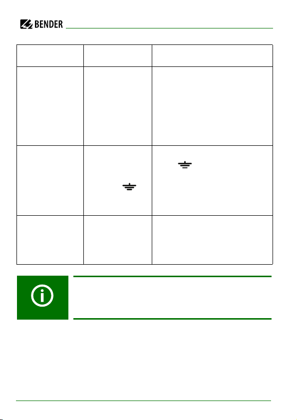
When a device or connection fault is found, the message "!Error!" appears on
the display, the device fault LED lights up, the relay K3 (31-32-34) switches and
the respective fault message (see table) is indicated. If such a device fault occurs, a self test is started again every minute. If no more malfunction is detected, the fault message is deleted automatically and the device fault LED
extinguishes.
During operation, the self test function can be started by pressing the TEST
button (internal or external). The self test can also be started automatically
every hour or every 24 h by selecting "ISO ADVANCED: Autotest" menu.
22
IRDH375_D00124_05_M_XXEN/01.2020
Page 22
Function
The alarm relays Alarm1/2 only switch after starting the self test function by
pressing the TEST button, that means if an automatic self test has been selected, the alarm relays do not switch.
3.4.2 Relay K3: device fault alarm and EDS common message
Rel ay K3 is in tended t o sig nal d evice an d con nect ion e rrors of th e ISO METER®.
K3 is permanently set to N/C operation, with the contacts 31-34 normally
closed, that means when a fault occurs, the relay deenergizes (K3: 31-32 connected).
Further details are described in "Chapter 3.4.1 Self test".
The settings for K3 are preset and cannot be adjusted.
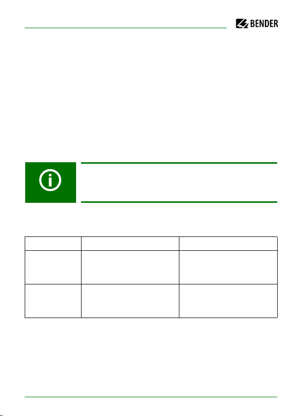
Behaviour of the analogue output
Setting Manual test Automatic test
0-20 mA 20 mA
while test procedure
4-20 mA 20 mA
while test procedure
0 mA
The current value depends
on the insulation value
4 mA
The current value depends
on the insulation value
IRDH375_D00124_05_M_XXEN/01.2020
23
Page 23
Error message Meaning Steps to be taken
Function
System
connection?
Connection PE? No low-resis-
Device error x Internal device
No low-resistance connection of terminals
L1, L2 to the IT
system
tance connection of the
terminals
and KE to earth
(PE)
error
If the on/off switching of the supply voltage is not possible
for technical reasons, a RESET of the process control can be
carried out by pressing the "INFO“, "RESET“ and "MENU“ key.
1. Check the wiring of
terminal L1, L2 to the IT
system.
2. Press the test button.
3. Switch the supply voltage
off and on.
4. Check the fuses.
1. Check wiring of terminal
and KE to earth (PE).
2. Press TEST button.
3. Switch the supply voltage
off and on.
1. Press TEST button.
2. Switch the supply voltage
off and on.
3. Contact Bender.
24
IRDH375_D00124_05_M_XXEN/01.2020
Page 24

Function
3.5 Additional functions IRDH375B
Current output for external measuring instrument
The current output of IRDH375B provides 0(4)…20 mA. The current output is
galvanically isolated from the device electronics and the RS-485 interface. The
ISO SETUP menu, on page 43, allows to switch over between 0…20 mA and
4…20 mA.
Real-time clock
The real-time clock serves as a time base for the memory and self test functions. At first, the correct time and date must be set in the menu
"ISO ADVANCED". If time and date are not set, a "C" (clock) is flashing in the
standard display. In the event of a supply voltage failure, time and date will be
stored for at least thirty days.
If the 24 h selftest is activated in the "ISO ADVANCED" menu, a special time of
day can be selected for the execution of the self test in the menu "TEST: 12:00".
Then a self test will be started automatically once a day exactly at the preset
time. If the 1 h auto test has been selected, the self test is automatically carried
out every full hour.
Interconnected IT systems
When using ISOMETER®s in IT systems, make sure that only one active
ISOMETER® is connected in each interconnected system. If IT systems are interconnected via coupling switches, make sure that ISOMETER®s not currently
used are disconnected and deactivated via a control system. IT systems coupled via diodes or capacitances may also influence the insulation monitoring
process. Hence, also in this case a central control of the different ISOMETER®s
is required.
IRDH375_D00124_05_M_XXEN/01.2020
25
Page 25

Function
Function input F1/F2 for connection or disconnection of
IT systems being monitored
The ISOMETER® can be disconnected from the IT system and set to STANDBY
mode with the function input F1/F2. If the input F1/F2 is bridged, the connections L1/L2 are switched off via internal coupling relays, the measuring function is stopped and the message "STANDBY" appears on the display. Software
version 1.4 or higher does not indicate the measured insulation resistance
during the disconnection, but indicates the value > 10 MΩ. Furthermore, the
alarm relays and alarm LEDs no longer provide alarm messages. After opening
the function input F1/F2, the connection to the IT system will be restored and
a completely new measuring cycle for insulation monitoring is started.
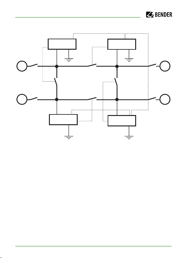
With this function, selective disconnection of an IRDH375B in interconnected
IT systems can be carried out via auxiliary contacts of the respective coupling
switch. One coupling switch each in a line-type or ring-type arrangement can
deactivate a subsequent IRDH375B. This arrangement guarantees that only
one ISOMETER® is active in each galvanically connected system. In a ring-type
arrangement with all coupling switches closed, it can be assumed that all
ISOMETER®s are deactivated. In order to prevent this, a BMS Master (IRDH375B
BMS address 1) monitors the condition of the function input F1/F2 of all Slave
ISOMETER®s.
When all Slave ISOMETER®s are in the STANDBY mode, the insulation monitoring function of the Master ISOMETER® and hence the function input F1/F2 of
the Master are without function in this mode.
Details are shown in the graphic below.
26
IRDH375_D00124_05_M_XXEN/01.2020
Page 26
BMS bus (A/B, RS485)
F1/F2
PE PE
PE PE
IT system 1 IT system 2
IT system 3IT system 4
G
G
G
G
Addr. 1
Addr. 2
Addr. 4
Addr. 3
IRDH375B
IRDH375B
IRDH375B
IRDH375B
F1/F2
F1/F2
F1/F2
Function
IRDH375_D00124_05_M_XXEN/01.2020
27
Page 27

Function
ISOnet Function (COM SETUP)
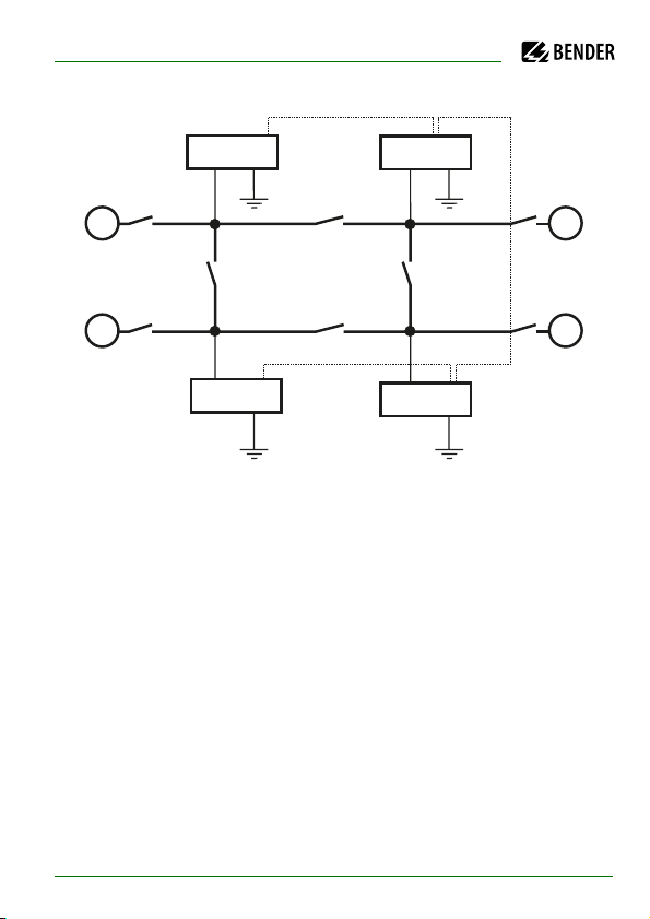
Select "ISOnet=ON" from the COM SETUP menu to activate this function. This
function is a type of scanning function. The BMS Master activated via the
ISOnet function controls the ISOnet Slave devices via the BMS bus. Once an
ISOMETER® has finished its measurement cycle, the authorization for measuring the insulation resistance is passed on from the ISOnet Master to the next
Slave. While an ISOMETER® is carrying out a measurement all other
ISOMETER®s are in the STANDBY mode. In this way it can be prevented that
the ISOMETER®s disturb each other in interconnected systems. In comparison
to the solution coupling switches and function input F1/F2, the response time
is prolonged, since no continuous measurement takes place. The advantage
is that no auxiliary contacts of a coupling switch are required. Furthermore,
this solution is ideally suited for capacitive IT systems or IT systems connected
via diodes.
An ISOnet Slave checks whether there is a Master available in the network. If
there is no Master available, the fault message "ISOnet Master?" appears on
the display after approximately 1 h. Additionally, the LED for device errors
lights and the Relay K3 switches. When the ISOnet function is activated, the
function input F1/F2 will be disconnected.
28
IRDH375_D00124_05_M_XXEN/01.2020
Page 28
BMS bus (A/B, RS485)
PE PE
PE PE
IT system 1 IT system 2
IT system 3IT system 4
G
G
G
G
Addr. 1
Addr. 2
Addr. 4
Addr. 3
IRDH375B
IRDH375B
IRDH375B
IRDH375B
Function
IRDH375_D00124_05_M_XXEN/01.2020
29
Page 29
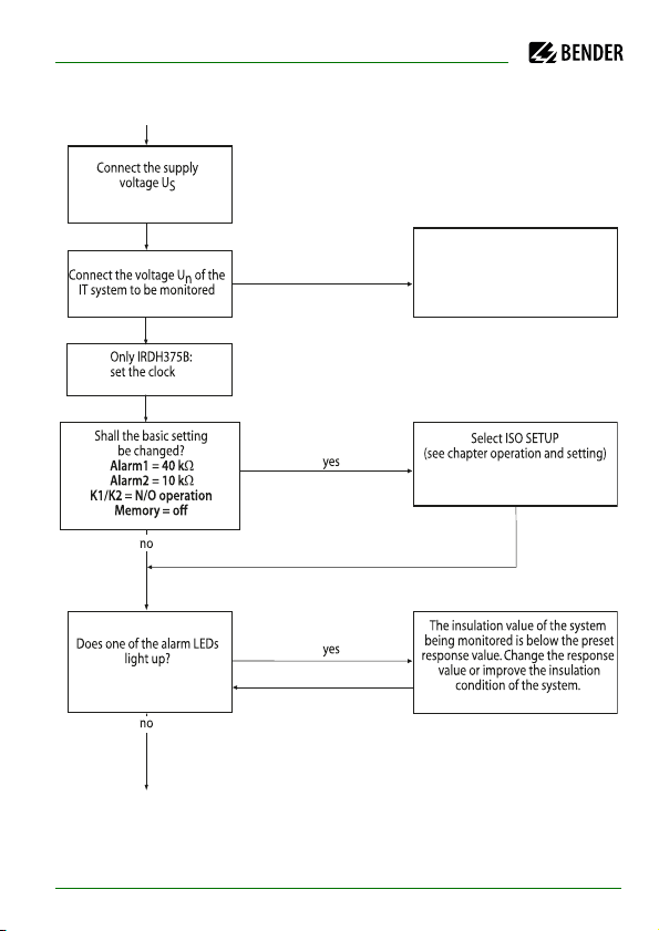
4. Commissioning flow chart (threepart)
Is the system to be monitored an
unearthed system (IT system)?
The IRDH375 is not suitable for this
application( contact BENDER).
Un is too high for direct
connection. A coupling device
providing the respective voltage
range must be connected.
Device connection
Optional device
connection
no
no
yes
The terminals L1 and L2 must be
connected to Un of the system to be
monitored according to the wiring diagram.
An external kW measuring instrument
at M+/M- with a display range of
10 kW...1000 kW,
Scale centre point: 120 kW
Output current IRDH375: 0...400 mA
Output current IRDH375B: 0/4...20 mA
Connect the supply voltage Us
to the terminals A1/+ and A2/-. Consider
the details indicated on the nameplate.
External TEST button (NO contact) to the
terminals T1 and T2
External RESET button (NC contact) to the
terminals R1 and R2
The output contacts of the alarm relays
System fault (31-32-34)
Alarm 1 (11-12-14)
Alarm 2 (21-22-24)
When using the RS485 interface, take care
that a 120 W resistor is connected at
the beginning and the end of the network.
Terminate IRDH...: S1 = ON
13
12
11
7
8
10
Deenergize the installation
before connecting the device!
Recommended wire cross section of
connecting cable
single wire 0.2...4 mm
2
flexible 0.2... 2.5 mm
2
Is the maximum nominal voltage
Un AC 793 V
or
Un
DC 650 V
yes
The two PE connections
and KE must
be connected separately to the
equipotential bonding.
6
2
3
4
5
1
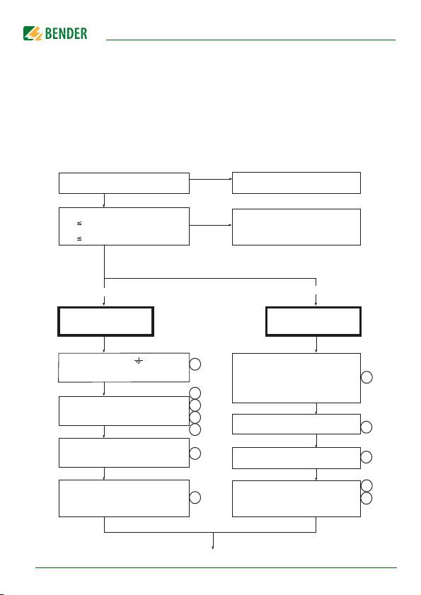
The encircled figures in the flow chart correspond to the figures in the legend
to the wiring diagram.
Commissioning of the ISOMETER® (1)
30
IRDH375_D00124_05_M_XXEN/01.2020
Page 30
Commissioning flow chart (threepart)
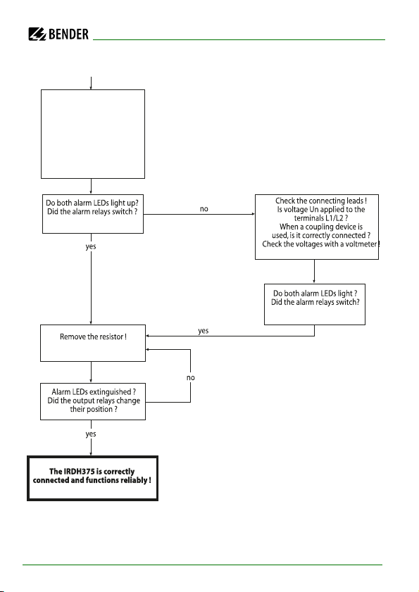
Commissioning of the ISOMETER® (2)
The ISOMETER® carries out a
self test. The display indicates
the insulation value after finishing
the measurement.
IRDH375_D00124_05_M_XXEN/01.2020
31
Page 31
Commissioning of the ISOMETER® (3)
In order to check the proper
connection, a functional test
using a resistance that is
suitable for the mains voltage
is to be carried out.
Size of the resistance:
50% of the present
response value Alarm2.
Commissioning flow chart (threepart)
32
IRDH375_D00124_05_M_XXEN/01.2020
Page 32

5. Connection
5.1 Wiring
IRDH375(B) has plug-in terminals.
Connect the terminals "A1/+" and "A2/-" to the supply voltage U
ance with IEC 60364-4-43. The connections to the supply voltage shall be provided with protective devices to afford protection in the event of a short
circuit (a 6 A fuse is recommended).
For UL and CSA applications, the use of 5 A fuses is mandatory.
Devices for protection against short-circuit in conformity with
IEC 60364-4-43 for the IT system coupling L1/L2 can be omitted if the wiring is
carried out in such a manner as to reduce the risk of a short-circuit to a minimum (a short-circuit-proof and earth-fault-proof wiring is recommended).
Only one ISOMETER® may be triggered by an external TEST or RESET button. A
galvanic parallel connection of several Test and Reset inputs for common testing of ISOMETER® is not permitted.
External coupling devices connected via the terminal AK cannot be switched
off via the internal coupling relays. If no coupling device is used, the terminal
AK remains free.
in accord-
S
IRDH375_D00124_05_M_XXEN/01.2020
33
Page 33
Connection
31042
PE
6
1
5
L1
L2
L3
L1
L2
L3
N
L+
L-
DC - System
L2L1
U
n
9
78
U
n
3/N AC-System
L2L1
U
n
3 AC-System
L2L1
L1
L2
AC-System
L2L1
U
n
mA
M+ M- T1 T2 R1 R2 F1 F2 A B 31 32 34 21 22 24 11 12 14
IRDH375
RS485
OFF
S2 S1
ON
K3
K2
K1
A1/+ A2/- L1 L2 AK KE
6 A
11
12
13
14
16
15
34
IRDH375_D00124_05_M_XXEN/01.2020
Page 34

Connection
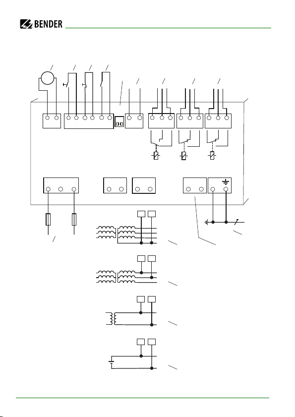
Legend to wiring diagram:
For external indicating instrument:
1
IRDH375: current output, not galvanically separated: 0 … 400 µA
IRDH375B: current output, galvanically separated: 0…20 mA or
4…20 mA
External TEST button (NO contact)
*2
External RESET button (NC contact or wire jumper),
*3
when the terminals are open, the fault message will not be stored
STANDBY by means of the function input F1, F2:
*4
When the contact is closed, insulation measurement does not take
place; system disconnection
S1 = ON: RS-485 interface (A/B) is terminated with 120 Ω resistor
5
S2 = unassigned
Serial interface RS-485 (A/B)
6
device fault relay K3; changeover contacts provided
7
Alarm relay K2; changeover contacts provided
8
Alarm relay K1; changeover contacts provided
9
Supply voltage Us (see nameplate) via 6 A fuse;
10
For UL and CSA applications, the use of 5 A fuses is mandatory
Connection to the 3NAC system to be monitored:
11
connect terminals L1, L2 to neutral conductor N
Connection to the 3 AC system to be monitored:
12
connect terminals L1, L2 to conductor L1, L2
Connection to the AC system to be monitored:
13
connect terminals L1, L2 to conductor L1, L2
Connection to the DC system to be monitored:
14
connect terminal L1 to conductor L+, terminal L2 to conductor L-
IRDH375_D00124_05_M_XXEN/01.2020
35
Page 35

Connection for external coupling devices (Extension of the nominal
15
voltage range U
16
Separate connection of and KE to PE
The terminal pairs 2, 3 and 4 must be wired so that they are
*
galvanically isolated and must not have a connection to PE.
)
n
Connection
36
IRDH375_D00124_05_M_XXEN/01.2020
Page 36
Connection
1
2
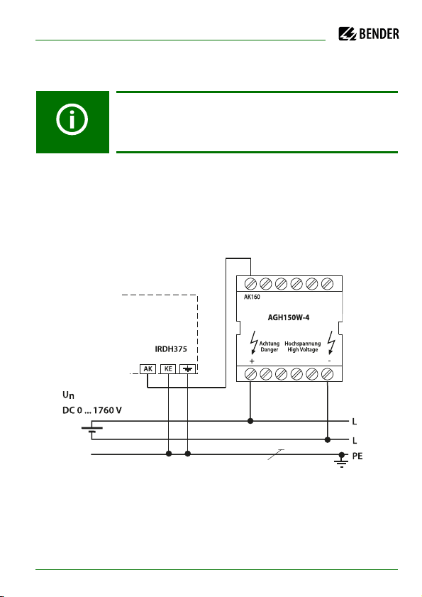
5.2 Wiring diagrams with coupling devices
Please observe the settings in the "ISO ADVANCED AGH“
menu ! Adapt the settings to the coupling device to be used.
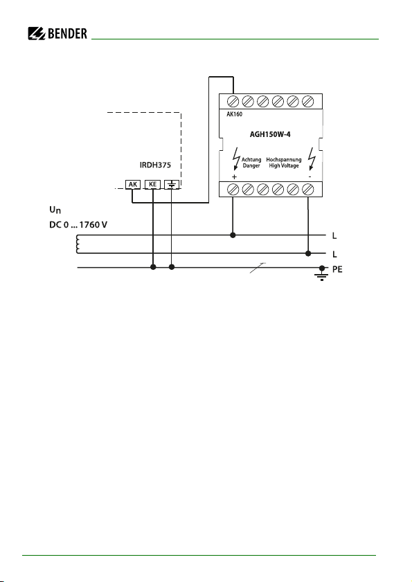
5.2.1 Connection with AGH150W-4
Connected to the ISOMETER® this coupling device extends the nominal voltage range to DC 1,760 V in DC systems.
IRDH375_D00124_05_M_XXEN/01.2020
37
Page 37
Connection
1
2
38
IRDH375_D00124_05_M_XXEN/01.2020
Page 38
Connection
2
534
AGH520S
PE
IRDH375
L1
L2
L3
U
n
3/(N) AC 0...7200 V 42...460 Hz
N
3 AC
3/N/ AC
KE
AK
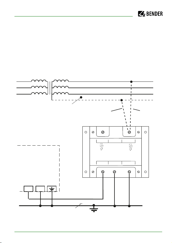
5.2.2 Connection with AGH520S
Connected to the ISOMETER® this coupling device extends the nominal voltage range to AC 7,200 V in pure AC systems. In case of 3AC systems, Pin 2 of
AGH520S is to be connected to L1, in case of 3/N AC systems, Pin 2 is to be connected to the N conductor.
IRDH375_D00124_05_M_XXEN/01.2020
39
Page 39
Connection
L1
L2
L3
PE
Un
N
AGH204S-4
1
2
AK160
AK80
U3
V3
W3
IRDH375
KE
AK
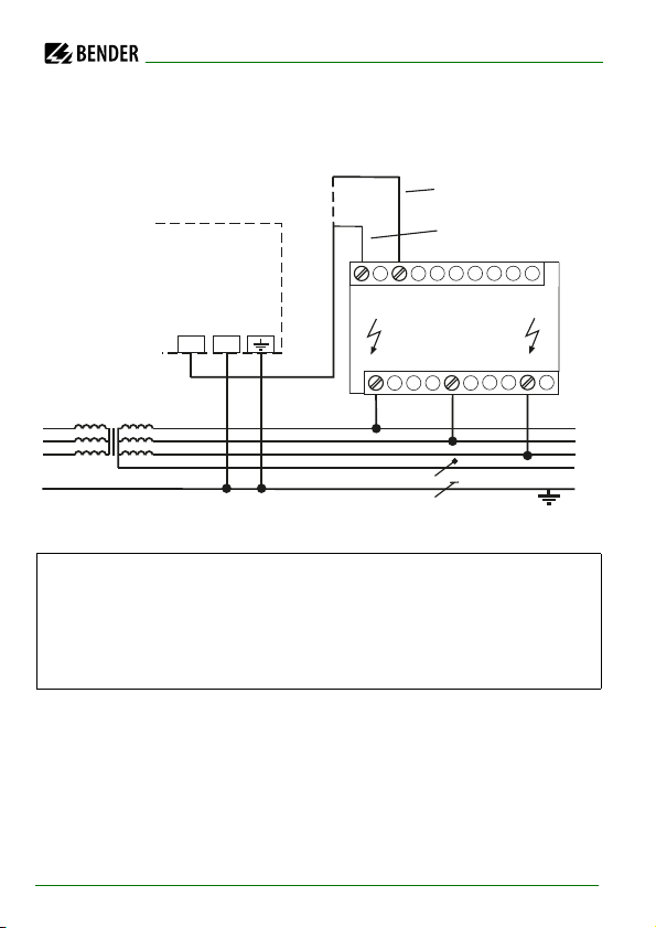
5.2.3 Connection with AGH204S-4
This coupling device extends the nominal voltage range of ISOMETER®s used
in AC systems including rectifiers.
without rectifiers U
1
with rectifiers
2
40
= 3AC 0…1,650 V (DC max. 1,000 V)
n
U
= 3AC 0…1,300 V (max. AC voltage; max. DC
n
voltage after rectifiers in intermediate circuits of
frequency converters: 1,840 V)
IRDH375_D00124_05_M_XXEN/01.2020
Page 40

Connection
The maximum DC voltage is the voltage permitted to occur in the AC part of
an IT system to PE when the IRDH375 is coupled with AGH204S-4 in this part
of the system. This voltage is dependent on the level of the nominal voltage,
the type of rectification 6 pulse, 12 pulse,…), the type of converter intermediate circuit (current… or voltage…), and the converter technology. In case of
converters, the maximum DC voltage in the intermediate circuit usually corresponds to the phase-to-phase voltage of the supplying AC system multiplied
by 1.414.
In case of current-controlled intermediate circuits of frequency converters,
higher DC voltages are to be expected.
The given voltage values for AC/DC systems take into account values found by
previous experience (factor 1.414 between DC voltage and AC voltage).
The maximum DC voltage in case of insulation faults in the DC part of the IT
system, for example converter intermediate circuit, is DC 1840 V. From this,
the maximum nominal AC voltage is calculated:
= DC 1,840 V/1.414 = AC 1,300 V
U
max
IRDH375_D00124_05_M_XXEN/01.2020
41
Page 41
6. Operation and setting
1234 56
7
8
A-ISOMETER® IRDH375
INFO TEST RESET MENU
ESC
12
k
W
Insulation fault
R =010K
W
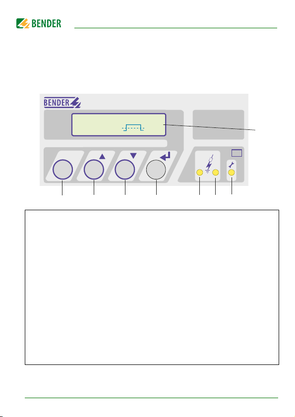
6.1 Operating features and displays IRDH375(B)
INFO key: to query standard information/
1
ESC key: back (menu function), confirmation parameter change
TEST button: to call up the self test/
2
Up key: parameter change, moving up in the menu
RESET button: to delete insulation fault alarms
3
Down key: parameter change, moving down in the menu
MENU key: to activate the menu system/
4
Enter key: confirmation parameter change
Alarm LED 1 lights: insulation fault, first warning level reached
5
Alarm LED 2 lights: insulation fault, second warning level reached
6
Device fault LED lights: IRDH375 defective
7
Two-line display for standard and menu mode
8
A detailed description of the operating elements is given on the following
pages.
42
IRDH375_D00124_05_M_XXEN/01.2020
Page 42
Operation and setting
1
2
3
4
Insulation Fault
Rs=011k
W . H
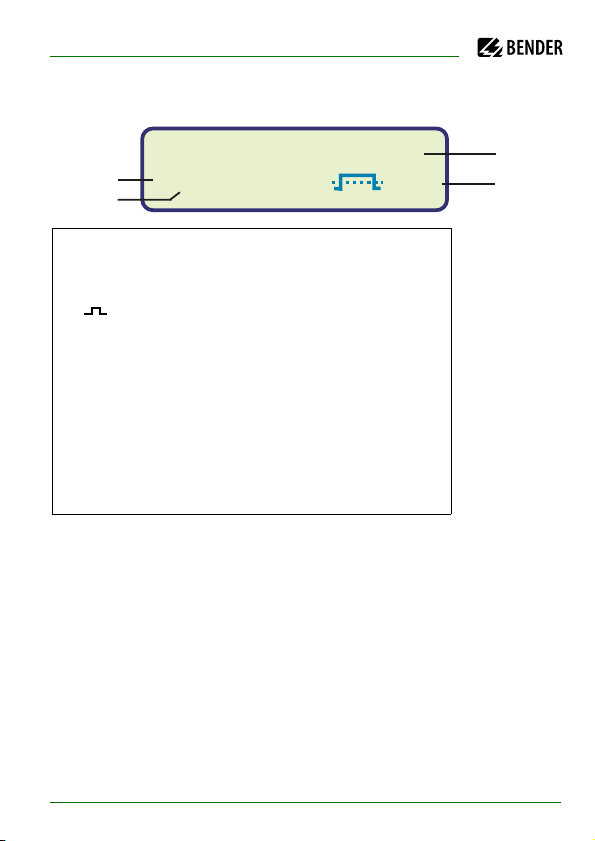
6.1.1 Display in the standard mode
Indication of the insulation resistance in kΩ
1
Additional information about the insulation resistance:
2
"s" = new measurement has started
= polarity of the measuring pulse
3
. = valid bus communication signals
H = new entry in the memory data base
C = flashing, clock is to be set
Messages:
4
- Insulation fault
- Connection system?
- Connection PE?
- Device error x
- ****STANDBY*****
IRDH375_D00124_05_M_XXEN/01.2020
43
Page 43
Operation and setting
1. EXIT
2. HISTORY INFO
INFO
ESC
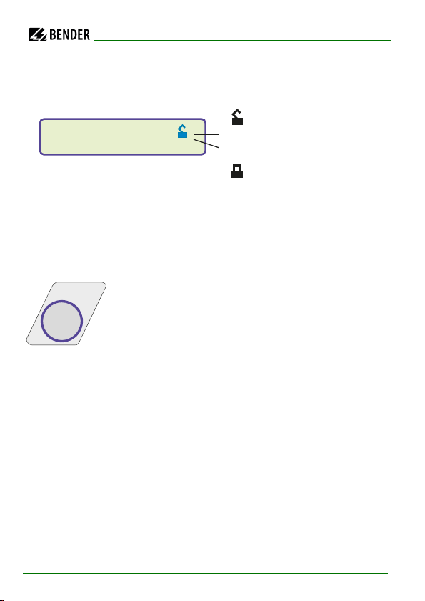
6.1.2 Display in the menu mode
Parameter change is
permitted.
Parameter change is
blocked,
enabling by a password
6.1.3 Function keys
Two functions are assigned to each function key. In addition to the basic function marked with a circle, all the keys allow navigation within the menu.
Pressing the INFO key provides the following information
without opening the menu:
Device name, firmware version
Response values Alarm 1 and Alarm 2
System leakage capacitance C
insulation resistances > 20 kΩ)
Setup status (for details refer to the table of the
status numbers on page 89)
COM-Setup (IRDH375 bus address)
Please have the details above on hand if you have a problem and if you contact Bender for technical questions.
(only indication if
e
44
IRDH375_D00124_05_M_XXEN/01.2020
Page 44
Operation and setting
TEST RESET
MENU
TEST
RESET
MENU
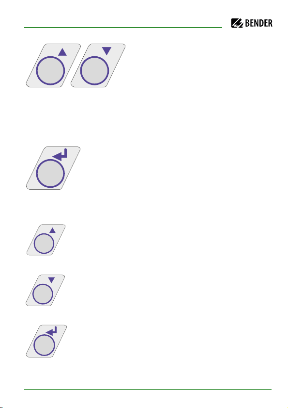
Activating the TEST button starts the
ISOMETER® self test.
Pressing the RESET button resets insula-
tion fault alarm messages stored in the
ISOMETER®. The memory function is only available after activating the fault
memory in the ISO SETUP menu or after bridging the terminals R1/R2. Furthermore, the ISOMETER® can only be reset when the present insulation value is
25 % higher than the set response value.
The menu system is called up by pressing the MENU key.
For controlling the menu system, the arrow keys, the ENTER key and the ESC
key are used:
Up key:
Moving up in the menu, increasing a parameter
Down key:
Moving down in the menu, reducing a parameter
ENTER key
Selecting a menu item or sub menu item, confirming or storing a parameter change and going back to the associated sub
menu item or going to the next input area.
IRDH375_D00124_05_M_XXEN/01.2020
45
Page 45
Operation and setting
INFO
ESC
ESC
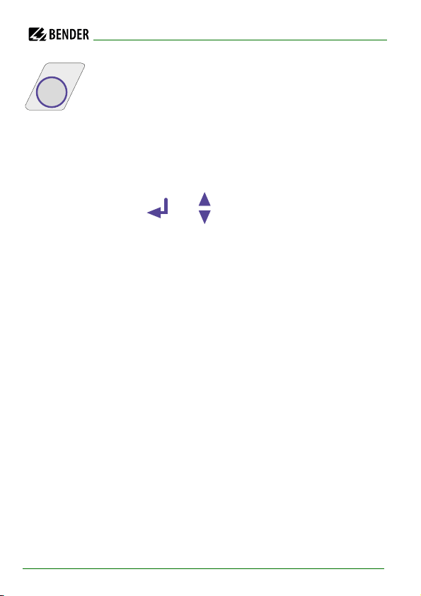
ESC key:
Returning from a sub menu to the previous menu.
If you do not quit the menu, the device automatically returns
to the standard mode again after approximately five minutes.
For the sake of clarity, the following symbols are used for the functions
ENTER, UP/DOWN and ESCAPE in the menu diagrams of this operating
manual:
46
IRDH375_D00124_05_M_XXEN/01.2020
Page 46

Operation and setting
6.2 Menu structure and menu mode
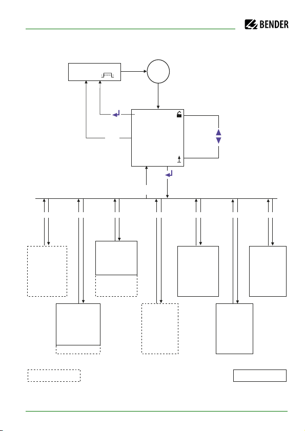
Switchover to the menu mode
After pressing the MENU key, you can change from the standard mode to the
menu mode. From the menu mode you can link to the different sub menus.
Navigation within the menu
Select the desired menu item using the UP/DOWN keys. The selected menu
item is indicated by a flashing cursor. Press the ENTER key to open the associated sub menu.
Use the UP/DOWN keys again to select the desired parameters. Move the cursor to the edit field by pressing the ENTER key.
If you have reached the end of the main menu list, it will be indicated by the
"Arrow UP" symbol.
Changing the parameters
When password protection is activated, indicated by the symbol "padlock
closed" , the first thing to enter is the correct password before the parameters can be changed using the UP/DOWN keys. Entering the correct password once allows all parameters to be changed as long as you do not leave
the menu.
Changing the parameter usually has an immediate effect on the measuring
and alarm functions. The changed parameter is stored in a volatile memor y by
pressing the ENTER or ESC key after returning to the sub menu (flashing cursor
in column 1). During menu operations, all measuring and alarm functions carry on working as usual in the background.
IRDH375_D00124_05_M_XXEN/01.2020
47
Page 47

Operation and setting
Changing from the menu mode to the standard mode
Pressing the ESC key allows fast changing from the menu mode to the standard mode. Thus, the menu item "EXIT" need not to be activated. Automatic
switchover from the menu mode to the standard mode takes place when no
key is pressed for approximately 5 min in a main or sub menu.
48
IRDH375_D00124_05_M_XXEN/01.2020
Page 48
Operation and setting
1. EXIT
2. HISTORY INFO
3. ISO SETUP
4. ISO ADVANCED
5. COM SETUP
6. PASSWORD
7. LANGUAGE
8. SERVICE
1. Exit
2. AGH : no
3. Ce max: 150 µF
4. Measure: AMP
5. Autotest: 24h
6. Clock: 19:08
7. Date: 01.01.01
8. Test: 00:00
1. Exit
2. Alarm1 040 kW
3. Alarm2 010 kW
4. K1 : N.O
5. K2 : N.O
6. Memory: on
7. M+/M-: 0-20 mA
Nr.: 01 #Nr.: 02
Power on
1. Exit
2. Addr: 003
3. ISONet: off
4. ISO Monitor
Insert Service
Password: XXX
ISO ADVANCEDISO SETUP COM SETUP SERVICE
1. Exit
2. Password: XXX
3. Status: off
PASSWORD
1. Exit
2. Text: Deutsch
LANGUAGE
IRDH375B
IRDH375
ESC
*** IT-SYSTEM ***
R >010 MW H
ESC
MENU
HISTORY INFO
6.2.1 Diagram menu structure
IRDH375_D00124_05_M_XXEN/01.2020
49
Page 49
Operation and setting
Data record Event Display indication
1 Switch the supply voltage on Power On
2 Lowest measured insulation value Rmin
3...99 Response value Alarm 1 released
Alarm1
3...99 Response value Alarm 1 cleared
Alarm1
3...99 Response value Alarm 2 released
Alarm2
3...99 Response value Alarm 2 cleared
Alarm2
3...99 Error system connection released
System connection?
3...99 Error system connection cleared
System connection?
3...99 Error PE connection released
PE connection?
3...99 Error PE connection cleared
PE connection?
3...99 Device error released
Device error
3...99 Device error cleared
Device error
3...99 System reset (watchdog) System reset
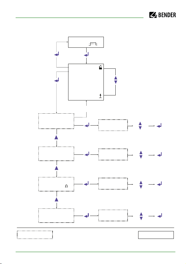
6.3 Menu HISTORY INFO (IRDH375B)
99 events with date and time stamp can be stored in the memory database.
The database is designed as a ring memory, i.e. the eldest entry is overwritten.
Data is written into a non-volatile memory and therefore provides protection
against voltage failure.
Before storing the events with the actual date and time stamp, set the realtime clock in the ISO ADVANCED menu (refer to page 59).
The following function keys are provided to query data from the
"HISTORY INFO" menu: the UP/DOWN keys to change the data record number,
the ENTER key to change from the data record number to the menu item
"Clear all:on" to delete the memory storage, and the ESC key to leave the
menu.
A new entry into the memory is signalled with an "H" on the display in the
standard mode. The "H" will be deleted as soon as the "HISTORY INFO" menu
is called up.
50
IRDH375_D00124_05_M_XXEN/01.2020
Page 50
Operation and setting
1. EXIT
2. HISTORY INFO
3. ISO SETUP
4. ISO ADVANCED
5. COM SETUP
6. PASSWORD
7. LANGUAGE
8. SERVICE
Nr.: 01 #Nr: 08
Power on
Nr.: 01 #Nr: 08
Clear all: off
Nr.: 01 #Nr: 08
28.08.01 17:43
Nr.: 02 #Nr: 08
Clear all: off
Nr.: 02 #Nr: 08
Rmin: 010k
Nr.: 02 #Nr: 08
25.08.01 10:13
Nr.: 02 #Nr: 08
Clear all: off
Nr.: 02 #Nr: 08
Clear all: off
ESC
IRDH375
IRDH375B
*** IT-SYSTEM ***
R >010 MW H
6.3.1 Diagram HISTORY INFO (IRDH375B)
IRDH375_D00124_05_M_XXEN/01.2020
51
Page 51

Operation and setting
6.4 Menu ISO SETUP: Setting of the basic ISOMETER® functions
All alarm functions such as Alarm 1 and Alarm 2 (prewarning and main alarm),
the operating principle of the alarm relays K1 and K2 (N.O = N/O operation,
N.C = N/C operation) and the fault storage behaviour are set in this menu. The
current output for the IRDH275B can be selected from two value ranges.
6.4.1 Response values Alarm 1 and Alarm 2
The response values Alarm 1 and Alarm 2 are selected with the UP/DOWN
keys and stored with the ENTER key.
6.4.2 Operating principle of the alarm relays
"K1"/"K2" are factory set to N.O Test, that means N/O op eration. When the supplement "Test" has been selected, the alarm relays switch over during a manual self test.
If, for any reason, the alarm relays may not switch over during a manual self
test, the settings N.C or N.O are to be selected.
K1: N.C Test = N/C operation contacts 11-12-14, with relay test
(the alarm relay is energized during normal operation)
K1: N.O Test = N/O operation contacts 11-12-14, with relay test
(the alarm relay is deenergized during normal operation)
K1: N.C = N/C operation contacts 11-12-14, without relay test
K1: N.O = N/O operation contacts 11-12-14, without relay test
K1: Flash = Flashing function contacts 11-12-14
(the alarm relay is energized during normal operation)
(the alarm relay is deenergized during normal operation)
(the alarm relay and the LED flash in the event of an alarm
message, approximately 0.5 Hz
52
IRDH375_D00124_05_M_XXEN/01.2020
Page 52

Operation and setting
K2: N.C Test = N/C operation contacts 21-22-24, with relay test
(the alarm relay is energized during normal operation)
K2: N.O Test = N/O operation contacts 21-22-24, with relay test
(the alarm relay is deenergized during normal operation)
K2 : N.C = N/C operation contacts 21-22-24, without relay test
(the alarm relay is energized during normal operation)
K2 : N.O = N/O operation contacts 21-22-24, without relay test
(the alarm relay is deenergized during normal operation)
K2 : Flash = Flashing function contacts 21-22-24
(the alarm relay and the LED flash in the event of an alarm
message, approximately 0.5 Hz)
IRDH375_D00124_05_M_XXEN/01.2020
53
Page 53
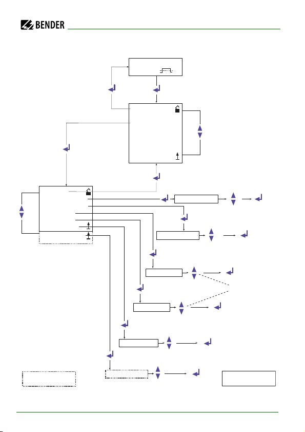
Diagram ISO SETUP
1. EXIT
2. HISTORY INFO
3. ISO SETUP
4. ISO ADVANCED
5. COM SETUP
6. PASSWORD
7. LANGUAGE
8. SERVICE
1. Exit
2. Alarm1: 100 KW
3. Alarm2: 200 KW
4. K1 : N.O
5. K2 : N.O
6. Memory: off
7. M+/M-: 0-20 mA
Alarm1 : 100 KW
Alarm2 : 200 KW
K1: N.O
K2: N.O
Memory: off
M+/M-: 0-20 mA
K1: N.O Test
K1: N.C Test
K1: Flash
K1: N.O
K1: N.C
Memory: on
Memory: off
M+/M-: 0-20 mA
M+/M-: 4-20 mA
IRDH375B
IRDH375
*** IT-SYSTEM ***
R >010 MW H
Operation and setting
54
IRDH375_D00124_05_M_XXEN/01.2020
Page 54
Operation and setting
During the automatic self test, the alarm relays are not
switched over.
6.4.3 Memory setting (on/off)
Memory: on = Fault memory is activated
The device must be reset with the RESET button after
clearing the fault.
Memory: off = Fault memory deactivated (factory setting)
6.4.4 Current output for external measuring instruments (IRDH375B)
Factory setting: 0…20 mA
The current output of the IRDH375 can be set to "0…20 mA" or "4…20 mA" via
the menu point "M+/M-:". The maximum load is 500 Ω.
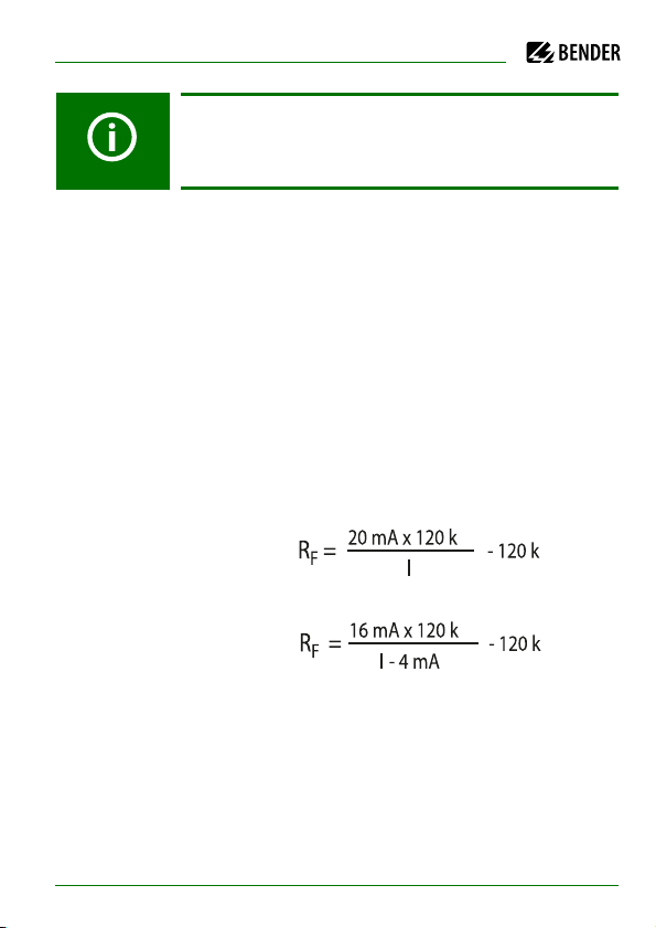
Function 0…20 mA:
= insulation fault,
R
F
I= current in mA
Function 4…20 mA:
R
= insulation fault,
F
I= current in mA
The associated characteristic curves are illustrated on page 85.
Ω
Ω
Ω
Ω
IRDH375_D00124_05_M_XXEN/01.2020
55
Page 55

Operation and setting
6.5 Menu ISO ADVANCED: Setting of the extended functions
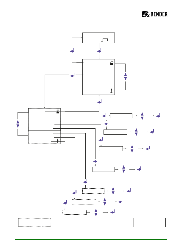
6.5.1 External coupling devices (AGH: no)
Basic setting "no", when no coupling device is used (factory setting).
AGH: 204 AK80
Terminal AK of the IRDH375 is connected to terminal AK80 of the
AGH204S-4. The nominal voltage range is extended to 3AC 0…1,650 V. Only
current converters with an output voltage not exceeding DC 1,000 V are allowed to be connected (see "operation with coupling device" on page 40).
AGH: 520S
Terminal AK of the IRDH375 is connected to terminal 5 of the AGH520S. The
nominal voltage range is extended to AC 0…7,200 V. Only current converters
with an output voltage not exceeding DC 1,000 V are allowed to be connected.
AGH: 204 AK160
Terminal AK of the IRDH375 is connected to terminal AK160 of the
AGH204S-4. The nominal voltage range is extended to 3AC 0…1,300 V. Only
current converters with an output voltage not exceeding DC 0…1,840 V are
allowed to be connected (see "operation with coupling device" on page 40).
56
IRDH375_D00124_05_M_XXEN/01.2020
Page 56
Operation and setting
AGH: 150 AK160
Terminal AK of the IRDH375 is connected to terminal AK160 of the
AGH150W-4. The nominal voltage range is extended to DC 0…1,760 V.
The coupling monitoring is deactivated when an external
coupling device is connected.
6.5.2 Adaptation to the system leakage capacitance
(Cemax : 150 µF)
This menu allows to adapt the ISOMETER® to the maximum system leakage
capacitance (max. 500 μF). Please note that the basic measuring time will be
increased to approximately 10 s when the setting is C
ting = 150 μF.
= 500 μF. Factory set-
e
6.5.3 Changing the measuring principle from AMP to DC (Measure: AMP)
The DC measuring principle is only suitable for pure AC systems.
Factory setting = AMP.
6.5.4 Setting the repetition time for automatic self tests (Autotest: 24h)
The time for the repetition of automatic self tests can either be set to 1 h or to
24 h or can be deactivated.
Factory setting = 24 h
IRDH375_D00124_05_M_XXEN/01.2020
57
Page 57

Operation and setting
6.5.5 Setting the real-time clock (Clock) (IRDH375B)
The setting of the real-time clock is the time base for the memory and for the
automatic self test. In case of failure of the supply voltage, the real-time clock
keeps running for approximately 30 days. When the device will be switched
on after this period, a flashing "C" appears on the display and the clock has to
be set again.
6.5.6 Setting the date (Date) (IRDH375B)
As well as the time, the date is required for the memory, too. In the event of
power supply failure, the date function is not influenced for at least 30 days. If
the device is switched on again after this period, a new setting of date and
time of the real-time clock is required.
6.5.7 Specifying the starting time of the automatic self test (Test) (IRDH375B)
If the 24h self test is activated in the ISO ADVANCED menu, it is possible to set
the time (hour) when the self test is to be carried out by means of the
"TEST: 12:00" sub menu. Then the self test is automatically carried out once a
day at a given time. If the 1 hour auto test has been selected, the self test will
be carried out at every full hour.
58
IRDH375_D00124_05_M_XXEN/01.2020
Page 58
Operation and setting
1. EXIT
2. HISTORY INFO
3. ISO SETUP
4. ISO ADVANCED
5. COM SETUP
6. PASSWORD
7. LANGUAGE
8. SERVICE
1. Exit
2. AGH: no
3. Ce max : 150µF
4. Measure: AMP
5. Autotest: 24h
6. Clock: 21:09
7. Date: 01.01.01
8. Test: 12:00
AGH: no
Ce max : 150µF
Autotest: 24h
no
150 AK160
204 AK160
520S
204 AK80
150µF
500µF
24h
no
01h
Clock: 21:09
Date: 01.01.01
Test: 00:00
00:00
.
.
.
23:00
IRDH375B
IRDH375
Measure: AMP
DC
AMP
*** IT-SYSTEM ***
R >010 MW H
6.5.8 Diagram ISO ADVANCED
IRDH375_D00124_05_M_XXEN/01.2020
59
Page 59
Operation and setting
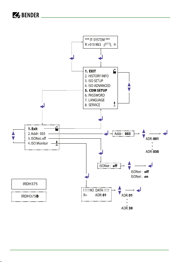
6.6 Menu COM SETUP: Setting the BMS interface
6.6.1 Bus address „Addr:“ (IRDH375B)
This menu item is used to set the BMS bus address of the IRDH375B. Since
there are several ISOMETER®s in one system, take care that the bus address is
not assigned twice.
The device is factory set to address 3 and hence acts as a Slave.
If several IRDH375 are operated on one BMS bus, the
addresses of other ISOMETER®s must be assigned one after
the other, since only one device may represent the Master.
6.6.2 ISOnet function (IRDH375B)
In the ISOnet = ON sub menu of the COM SETUP, the ISOnet function can be
set. The ISOnet function of all ISOMETER®s existing in the system must be in
"ON" position.
A BMS Master with the ISOnet function activated, controls the ISOnet Slave
devices via the BMS bus. If an ISOMETER® has completed the measuring cycle,
the permission for insulation measurement is given from the ISOnet Master to
the next Slave. During the measurement process carried out by an ISOMETER®, all other ISOMETER®s are in the STANDBY mode.
60
IRDH375_D00124_05_M_XXEN/01.2020
Page 60
Operation and setting
<<Bus SCANNING>>
R= K ADR:02
!!!!NO DATA!!!!
R= K ADR:02
Insulation Fault
R= 010K ADR:03
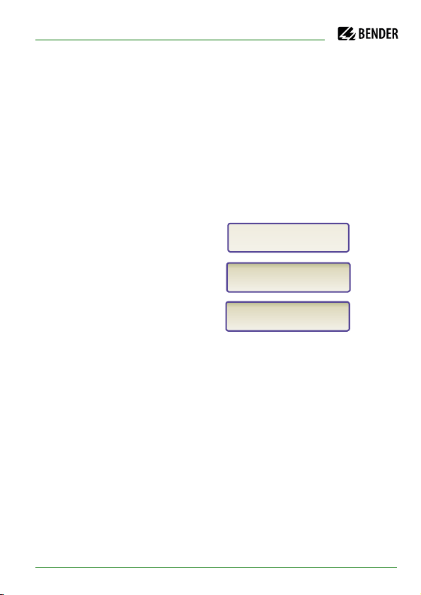
6.6.3 ISO monitor (IRDH375B)
This function allows to query the current measured value as well as the messages of all bus-capable ISOMETER®s existing in the BMS network. After selecting the bus address, the entire information stored by the selected device is
indicated on the display. The display indication is structured similar to the
standard indication, but instead of the indication of the measuring pulse, the
selected bus address is indicated. Without pressing a key, the indication
changes to the standard indication of the IRDH375B after about five minutes.
If there is no information available from the selected ISOMETER®, the message
"!!!!NO DATA!!!!" will be displayed.
Information is being searched
No data found
Current data address 03
IRDH375_D00124_05_M_XXEN/01.2020
61
Page 61
6.6.4 Diagram COM SETUP (IRDH375B)
Operation and setting
62
IRDH375_D00124_05_M_XXEN/01.2020
Page 62

Operation and setting
6.7 Menu PASSWORD
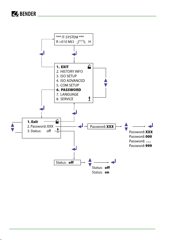
6.7.1 Activating and setting the password
This menu can be used to activate a password query. This protects the ISOMETER® against unauthorized settings and modifications. The desired password
(menu item "2. Password: xxx") can be set with the UP/DOWN keys and confirmed with the ENTER key. The password can be activated in the menu item
"3. Status: on" by clicking the ENTER key. The basic setting is "3. Status: off",
that means that the password is deactivated.
IRDH375_D00124_05_M_XXEN/01.2020
63
Page 63
6.7.2 Diagram PASSWORD
Operation and setting
64
IRDH375_D00124_05_M_XXEN/01.2020
Page 64

Operation and setting
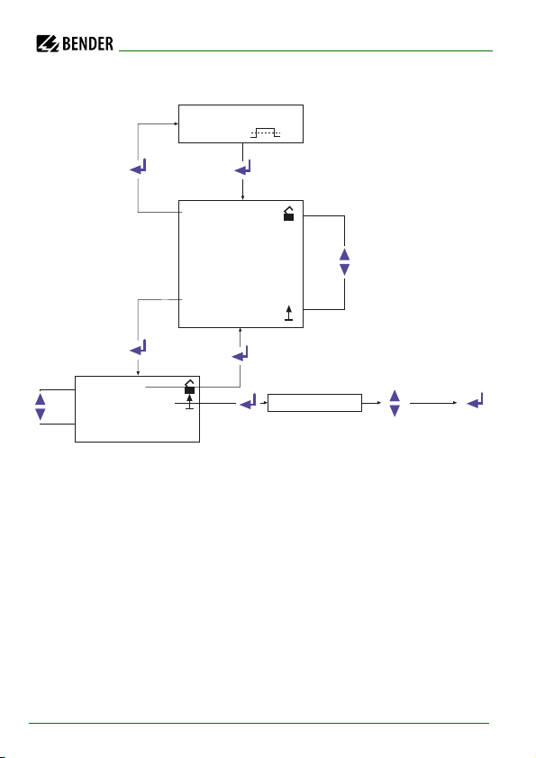
6.8 Menu LANGUAGE
6.8.1 Setting the national language
The menu item "LANGUAGE" allows fault messages of the ISOMETER® to be
set to different languages. There is the choice of "German" and "English".
The device menu is not influenced by the language selection.
IRDH375_D00124_05_M_XXEN/01.2020
65
Page 65
Operation and setting
1. EXIT
2. HISTORY INFO
3. ISO SETUP
4. ISO ADVANCED
5. COM SETUP
6. PASSWORD
7. LANGUAGE
8. SERVICE
1. Exit
2. Text: Deutsch
2. Text: Deutsch
2. Text: Deutsch
2. Text: English
*** IT-SYSTEM ***
R >010 MW H
6.8.2 Diagram LANGUAGE
6.9 Menu SERVICE
This menu item is provided for the Bender service personnel and is protected
by a password against erroneous settings. It is intended to provide fast fault
clearance by qualified experts in the event of a device error.
66
IRDH375_D00124_05_M_XXEN/01.2020
Page 66

Operation and setting
6.10 Parameterization via Internet
The parameters of an IRDH375B indicated below can be checked and set from
a remote place of use by using a personal computer. In addition, a browser
(viewing program for Internet application) and the BMS Ethernet Gateway
COM465 are required.
Remote setting is possible for:
Response value alarm 1 (1 kΩ…10 MΩ)
Response value alarm 2 (1 kΩ…10 MΩ)
Operating principle alarm relay K1 (e.g. N/O operation)
Operating principle alarm relay K2 (e.g. N/O operation)
Measuring principle (AMP or DC)
Current output ranges for external measuring instruments
(0/4…20 mA)
Maximum system leakage capacitance (150 μF or 500 μF)
Time for repetition of the automatic self test (off/1 h/24 h)
Starting time of the automatic self test (0.00…23.00 h)
Language of the alarm messages to be displayed (D, GB)
Setting the fault memory to "on" or "off"
IRDH375_D00124_05_M_XXEN/01.2020
67
Page 67
7. Serial interfaces
The ISOMETER®s IRDH375 and IRDH375B have differently designed serial interfaces.
IRDH375
- not galvanically isolated
- ASCII, unidirectional
- RS-485 and BMS protocol
- RS-485 and IsoData protocol
IRDH375B
- galvanically isolated
- ASCII, bidirectional
7.1 RS-485 interface with IsoData protocol (IRDH375)
Data transmission is continuously carried out and can neither be interrupted
by the data slave station nor be influenced in any other way. This protocol
cannot be used in combination with the BMS protocol.
For data evaluation via PC or Laptop, the terminal software "IsoData" and an
interface converter of the ASCII RS-485/RS-232 type is required. To obtain the
software, please contact Bender Service. Contact details are found on page 8.
Interface data:
RS-485 interface galvanically isolated from the device electronics
Connection to terminal A and B
Maximum cable length 1,200 m
Transmission protocol 9,600 baud - 1 start bit - 1 stop bit - 8 data bit
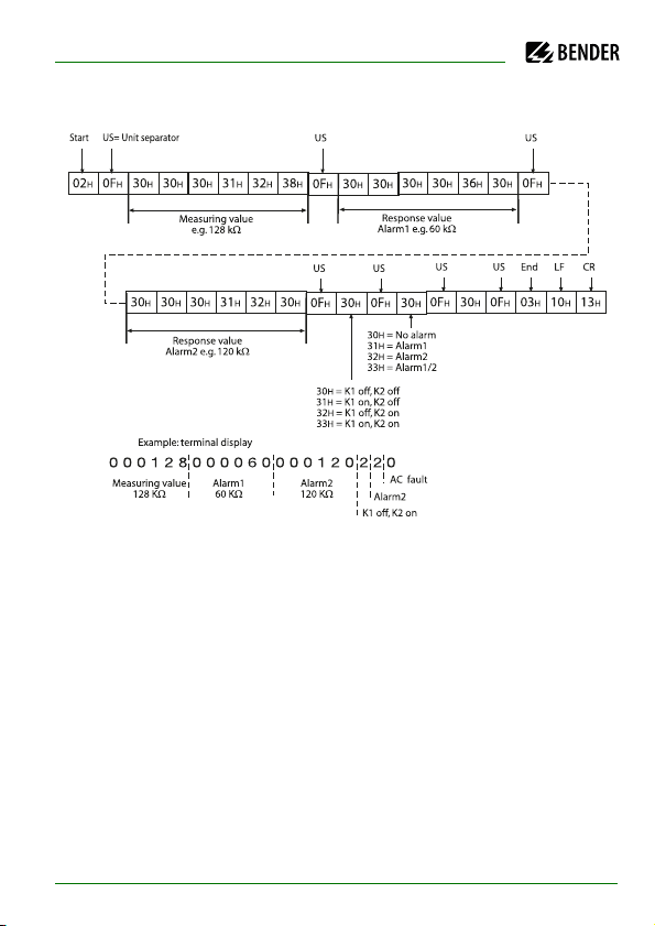
After each valid measurement, the following data block is provided:
68
IRDH375_D00124_05_M_XXEN/01.2020
Page 68
Serial interfaces
IRDH375_D00124_05_M_XXEN/01.2020
69
Page 69
Serial interfaces
AB AB AB
1st device ... device last device
120 W
0.4 W
120 W
0.4 W
Stub feeder
maximum 1 m
Maximum length of the RS485 bus: 1200 m
7.2 RS-485 interface with BMS protocol (IRDH375B)
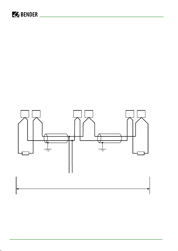
The RS-485 interface galvanically isolated from the device electronics and current output serves as a physical transmission medium for the BMS protocol. If
several IRDH375B or other bus-capable devices are interconnected in a network via the BMS bus, the BMS bus must be terminated at both ends with a
120 Ω resistor.
An RS-485 network that is not terminated, is likely to get instable and may result in malfunctions. Only the first and the last device in one line may be terminated. Devices in between must not be terminated with 120 Ω. Hence, stub
feeders in the network must not be terminated. The length of the stub feeders
is restricted to 1 m.
70
IRDH375_D00124_05_M_XXEN/01.2020
Page 70
Serial interfaces
7.3 Topology RS-485 network (IRDH375B)
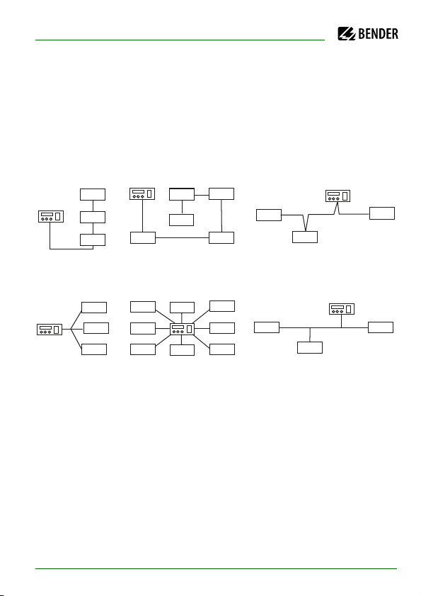
The optimum topology for the RS-485 network is a daisy-chain connection. In
this connection, device 1 is connected to device 2, device 2 to device 3, device
3 to device n etc. The RS-485 network represents a continuous path without
branches.
7.3.1 Correct arrangement
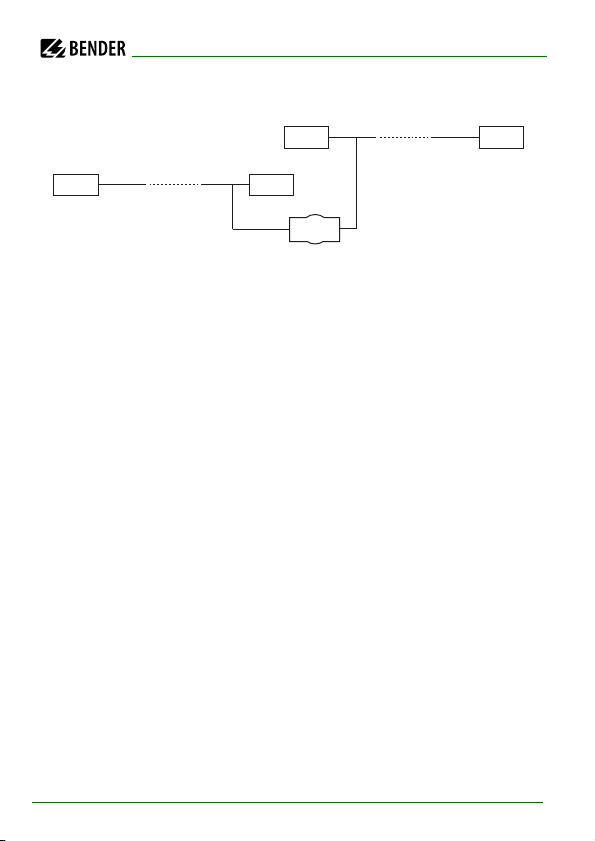
Three examples for correct arrangement:
7.3.2 Wrong arrangement
Three examples for wrong arrangement:
7.3.3 Wiring
A suitable type of cable for the wiring of the RS-485 network is:
screened cable, core diameter 0.6 mm
(e.g. J-Y(St)Y 2x0.6), screen on one side connected to earth (PE).
Connection to the terminals A and B.
IRDH375_D00124_05_M_XXEN/01.2020
71
Page 71
Serial interfaces
DI1
1
32
33
64
The number of bus nodes is restricted to 32 devices. When more devices are
to be connected, Bender recommends to use an RS-485 repeater DI1.
7.4 BMS protocol (IRDH375B)
This protocol is an essential part of the Bender Measuring Device Interface.
Data transmission generally makes use of ASCII characters.
Interface data are:
Baud rate: 9,600 baud
transmission: 1 start bit, 7 data bits, 1 parity bit, 1 stop bit (1, 7, E, 1)
Parity: even
Checksum: sum of all transmitted bytes = 0 (without CR and LF)
The BMS bus protocol works according to the Master/Slave principle. That
means that one device represents the Master while all other bus nodes are
Slaves. It is important that only one Master is present in each network. All bus
nodes are identified by a unique address. The Master scans all other devices
on the bus cyclically, listens to their signals and then carries out specific commands. Bus address 1 must be assigned to the Master, thus to one of the
IRDH375B devices.
72
IRDH375_D00124_05_M_XXEN/01.2020
Page 72
Serial interfaces
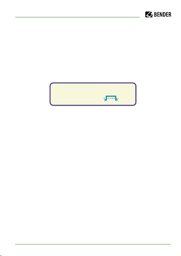
Fault RS485
Rs=011k
W . H
7.4.1 BMS Master
A Master can query all warning and operating messages from a Slave.
If the bus address 1 has been selected for one IRDH375B, this device automatically represents the Master, that means that all addresses between 1 and 150
are cyclically scanned via the BMS bus for alarm and operating messages. If
the Master receives no answer from five subsequent addresses, the scanning
cycle is started again. If the Master recognizes incorrect answers from a Slave,
the fault message "Fault RS485" is issued by the Master.
IRDH375_D00124_05_M_XXEN/01.2020
73
Page 73
Serial interfaces
***IT-SYSTEM***
R+=500K
Faults may be caused when:
Addresses are assigned twice
A second Master exists on the BMS bus
Interference signals occur on the bus lines
A defective device is connected to the bus
Terminating resistors are not activated
7.4.2 BMS Slave
All IRDH375B are factory set to Slave mode (address 3). In a BMS network, one
address must be selected from the address range 2…30 for each Slave. There
may be no gaps of more than five subsequent addresses, so that all Slaves can
be scanned by the Master. For IRDH375B a BMS address can be selected from
the address range 1 … 30. When assigning the addresses, also other devices
such as the EDS47x-12 must be considered.
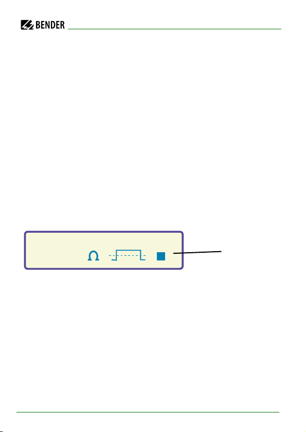
The correct reception of BMS data is indicated by a flashing point on the display on the right of the measuring pulse indication.
Flashing point:
BMS data received
If no flashing point appears, it may be attributed to the following:
No Master available in the network
More than one Master available in the network
RS-485 interface (terminal A/B) not connected or reversed
74
IRDH375_D00124_05_M_XXEN/01.2020
Page 74
Serial interfaces
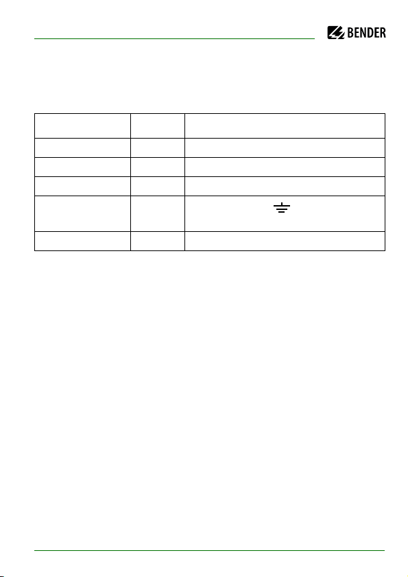
The following table gives an overview about essential alarm messages and
the assignment of the messages indicated on the display or operator panels,
e.g. PRC1470.
Message Channel Meaning
Insulation Fault 1 Insulation resistance < setting Alarm 1
Insulation Fault 2 Insulation resistance < setting Alarm 2
Connection system 3 Connection error L1/L2 against system
Connection PE
Connection error /KE against PE con-
4
ductor
Device error 5 Internal device error
The BMS function is completely available in the standby mode
(Stand-by: F1/F2).
7.4.3 Commissioning of an RS-485 network with BMS protocol
Connect the terminals A and B of all bus nodes in one line
Switch the terminating resistors on at the beginning and end of the
RS-485 network or in case of devices without a terminating switch, at
the end of the bus, connect a 120 Ω resistor to the terminals A and B.
Switch the supply voltage U
Determine one IRDH375 as the Master and assign address 1.
Assign the addresses (2…30) subsequently to all other IRDH375B
devices and other bus nodes (see table below).
Check whether a flashing point appears on all devices
(BMS commands are being received).
The sub menu "ISO-Monitor" in the COM SETUP menu allows insulation
values of the ISOMETERs® to be queried. Before starting the query, the
address of the ISOMETER® has to be entered.
S
on.
IRDH375_D00124_05_M_XXEN/01.2020
75
Page 75
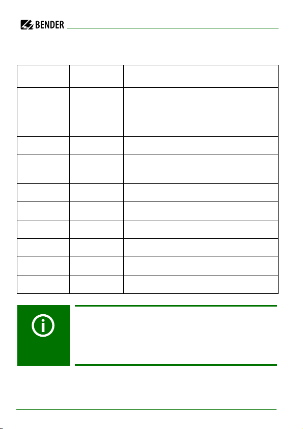
BMS bus address ranges
Addresses* Device Meaning
Serial interfaces
0 There is no device with address 0 !
1 PRC1470 Control and indicating device
1…30 IRDH275B/
375B/575
1…30 COM465 Protocol converter
2…30 EDS47x-12 Insulation fault evaluators (localisation)
31…60 SMO480-12 Signal converter relay
61…90 EDS47xE-12 Insulation fault evaluators (localisation)
111…119 PGH47x Test device for insulation fault location
121…150 PGH47xE Test device for insulation fault location
Malfunctions due to wrong address assignment!
Assigning wrong addresses to external devices may cause
malfunctions. When assigning addresses, take care that
there are no gaps greater than five in the respective ranges
(1…30, 31…60, 61…90, 111…119 and 121…151) .
Information sent to address 0 applies to all
devices connected to the interface (broadcast)
Insulation monitoring device
76
IRDH375_D00124_05_M_XXEN/01.2020
Page 76
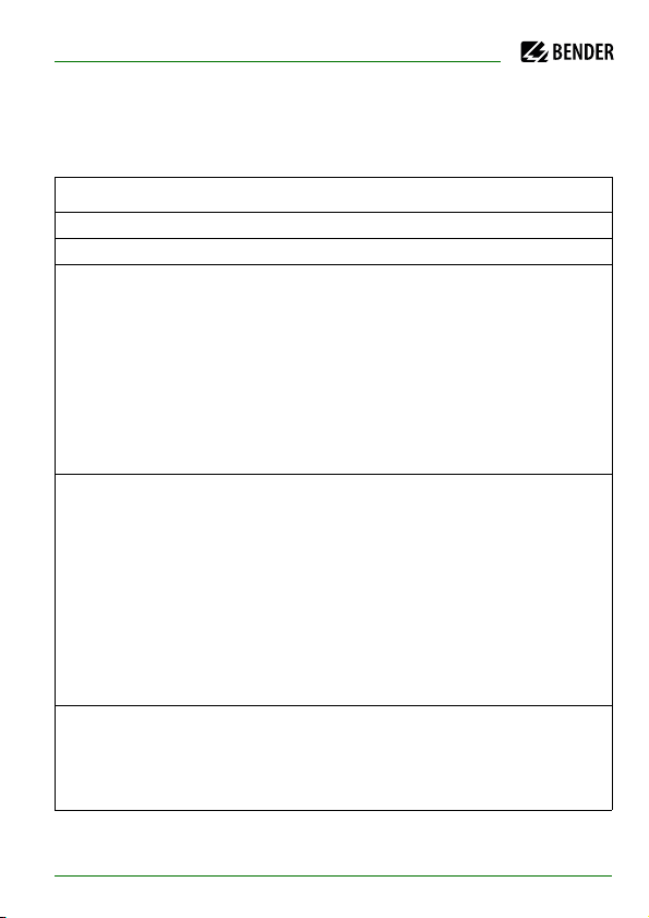
8. Factory Settings
Menu Submenu Factory setting
1. EXIT
2. HISTORY INFO
3. ISO SETUP 1. Exit
2. Alarm1: 40 kΩ
3. Alarm2: 10 kΩ
4. K1: N.O
5. K2: N.O
--------- K3: N.C fixed setting
6. Memory: off
7. M+/M-:* 0-20 mA*
4. ISO ADVANCED 1. Exit
2. AGH: no
3. Ce. max: 150 μF
4. Measure: AMP
5. Autotest: 24h
6. Clock:* CET (HH:MM)*
7. Date:*
8. Test:* 12:00*
5. COM SETUP* 1. Exit*
2. Addr:* 3 (Slave)*
3. ISOnet:* off*
4. ISO Monitor:*
current date
(DD.MM.YYYY)*
IRDH375_D00124_05_M_XXEN/01.2020
77
Page 77

Factory Settings
Menu Submenu Factory setting
6. PASSWORD 1. Exit
2. Password: 000
3. Status: off
7. LANGUAGE 1. Exit
2. Text: German
8. SERVICE (Access only for Bender service personnel)
* Settings apply only to IRDH375B.
Please check if the basic setting of the ISOMETER® complies with the requirements of the system to be monitored.
78
IRDH375_D00124_05_M_XXEN/01.2020
Page 78

9. Technical data IRDH375(B)
9.1 Data in tabular form
The values marked with * are absolute values
Insulation coordination acc. to IEC 60664-1
Rated voltage.....................................................................................................................................................AC 800 V
Rated impulse voltage/pollution degree..............................................................................................................8 kV/3
Voltage ranges
IRDH375….:
Nominal voltage range U
Nominal frequency f
Nominal voltage range U
IRDH375….-435:
Supply voltage U
Frequency range U
Supply voltage U
IRDH375….-427:
Supply voltage U
IRDH375….:
Power consumption .......................................................................................................................................... ≤ 14 VA
Response values
Response value R
Response value R
Relative uncertainty (20 kΩ…1 MΩ) (acc. to IEC 61557-8:2007-01) ............................................................. ±15 %
Relative uncertainty (1 kΩ…20 kΩ)......................................................................................................+2 kΩ/+20 %
Relative uncertainty (1 MΩ…10 MΩ)................................................................................................ 0.2 MΩ/+20 %
Response time t
Measuring time...........................................................................................................................see characteristic curve
Hysteresis (1 kΩ…10 kΩ) ................................................................................................................................... +2 kΩ
Hysteresis (10 kΩ…10 MΩ)................................................................................................................................. 25 %
.......................................................................................................... AC/3NAC 0…793 V*
n
(for f < 50 Hz see characteristic curve on page 85) ............................................0.1…460 Hz
n
...................................................................................................................... DC 0…650 V*
n
(see nameplate).......................................................................................................AC 88…264 V*
s
................................................................................................................................... 42…460 Hz
s
(see nameplate)...................................................................................................... DC 77…286 V*
s
(see nameplate)..................................................................................................... DC 19.2…72 V*
s
(Alarm 1) ...............................................................................................................1 kΩ …10 MΩ
an1
(Alarm 2) ...............................................................................................................1 kΩ …10 MΩ
an2
at RF = 0.5 x Ran and Ce = 1 μF............................................................................................... ≤ 5 s
an
IRDH375_D00124_05_M_XXEN/01.2020
79
Page 79

Technical data IRDH375(B)
Measuring circuit
Measuring voltage U
Measuring current I
Internal DC resistance R
Internal impedance Z
Permissible extraneous DC voltage U
Permissible system leakage capacitance C
........................................................................................................................................ ≤ 40 V
m
max. (at RF = 0 Ω)...................................................................................................... ≤ 220 μA
m
.................................................................................................................................. ≥ 180 kΩ
i
, at 50 Hz....................................................................................................................... ≥ 180 kΩ
i
..................................................................................................... ≤ DC 1200 V
fg
................................................................................................... ≤ 500 μF
e
Factory setting....................................................................................................................................................... 150 μF
Displays
Display, illuminated.............................................................................................................................. two-line display
Characters (number of characters)....................................................................................................................... 2 x 16
Display range , measuring value ............................................................................................................ 1 kΩ…10 MΩ
Operating uncertainty (20 kΩ…1 MΩ) (acc. to IEC 61557-8:2007-01) .................................................... ±15 % **
/
Operating uncertainty (1 kΩ…20 kΩ)............................................................................................. ±1 kΩ
±15 % **
Operating uncertainty (1 MΩ…10 MΩ).................................................................................... ±0.1 MΩ/±15 % **
** = under test conditions in accordance with IEC 61326-2-4, the tolerances may double
Outputs/inputs
TEST/RESET button .............................................................................................................................. internal/external
Cable length TEST/RESET button external ..........................................................................................................≤ 10 m
Current output for measuring instrument SKMP (scale centre point = 120 kΩ):..........................................................
Current output IRDH375 (load) ...................................................................................................... 400 μA (≤ 12.5 kΩ)
Current output IRDH375B (load) ........................................................................................................ 20 mA (≤ 500 Ω)
Accuracy current output (1 kΩ…1 MΩ)
in relation to the displayed measured value ........................................................................................ ±10 %, ±1 kΩ
Serial interface
Interface / Protocol IRDH375...................................................................................................... RS-485/ASCII-IsoData
Interface / Protocol IRDH375B................................................................................................................... RS-485/BMS
Connection ................................................................................................................................................ terminals A/B
Cable length .................................................................................................................................................. ≤ 1,200 m
Recommended cable (screened, screen on one site connected to PE)................................................ J-Y(St)Y 2 x 0.6
Terminating resistor................................................................................................................................. 120 Ω (0.5 W)
Device address, BMS bus .................................................................................................. 1…30 (factory setting = 3)
80
IRDH375_D00124_05_M_XXEN/01.2020
Page 80

Technical data IRDH375(B)
Switching components
Switching components...............................................................................................................3 changeover contacts:
................................................................................................................ K1 (Alarm 1), K2 (Alarm 2), K3 (device fault)
Operating principle K1, K2 (Alarm 1/Alarm 2).............................................................................N/O or N/C operation
Factory setting (Alarm 1/Alarm 2)........................................................................................................... N/O operation
Operating principle K3 ............................................................................................................................. N/C operation
Electrical endurance...........................................................................................................12,000 switching operations
Contact class ...................................................................................................................................... IIB (IEC 60255-23)
Rated contact voltage.......................................................................................................................AC 250 V/DC 300 V
Protective separation up to ........................................................................................................................ AC/DC 150 V
Making capacity...............................................................................................................................................AC/DC 5 A
Breaking capacity............................................................................................................... 2 A, AC 230 V, cos phi = 0.4
.......................................................................................................................................... 0.2 A, DC 220 V, L/R = 0.04 s
Contact current at DC 24 V ................................................................................................................. ≤ 2 mA (50 mW)
General data
EMC ................................................................................................................. acc. to IEC 61326-2-4:2006-06 Ed. 1.0
Shock resistance IEC 60068-2-27 (device in operation)............................................................................. 15 g/11 ms
Bumping IEC 60068-2-29 (during transport)................................................................................................40 g/6 ms
Vibration resistance IEC 60068-2-6 (device in operation)................................................................. 1 g/10…150 Hz
Vibration resistance IEC 60068-2-6 (during transport) .................................................................... 2 g/10…150 Hz
Ambient temperature (during operation)......................................................................................... -10 °C…+55 °C
Storage temperature range.................................................................................................................-40 °C…+70 °C
Climatic class acc. to IEC 60721-3-3........................................................................................................................ 3K5
Operating mode............................................................................................................................ continuous operation
Mounting ..............................................................................................................................as indicated on the display
Distance to adjacent devices ............................................................................................................................≥ 30 mm
Connection............................................................................................................................................. screw terminals
Connection, rigid, flexible.............................................................................................. 0.2…4 mm
2
/0.2…2.5 mm
Connection, flexible with connector sleeve, without/with plastic sleeve......................................... 0.25…2.5 mm
Conductor sizes (AWG)...................................................................................................................................... 24…12
Protection class, internal components (DIN EN 60529) ...........................................................................................IP30
Protection class, terminals (DIN EN 60529)..............................................................................................................IP20
Protection class, front plate mounted in panel (DIN EN 60529)..............................................................................IP40
Protection class with transparent front plate cover..................................................................................................IP65
2
2
IRDH375_D00124_05_M_XXEN/01.2020
81
Page 81

Technical data IRDH375(B)
Type of enclosure .................................................................................................................... X300, free from halogen
DIN rail mounting ........................................................................................................................................... IEC 60715
Flammability class ............................................................................................................................................UL94 V-0
Software version IRDH375 ............................................................................................................................ D183 V1.8
Software version IRDH375B .......................................................................................................................... D184 V1.8
Weight approx. ...................................................................................................................................................... 510 g
Option "W"
Shock resistance IEC 60068-2-27 (Device in operation) ............................................................................. 30 g/11 ms
Bumping IEC 60068-2-29 (during transport)................................................................................................ 40 g/6 ms
Vibration resistance IEC 60068-2-6 .............................................................................................. 1.6 mm/10…25 Hz
............................................................................................................................................................. 4 g/25…150 Hz
Ambient temperature (during operation) ......................................................................................... -25 °C…+70 °C
Storage temperature range ............................................................................................................... -40 °C…+85 °C
Screw mounting ................................................................................................................................................... 2 x M4
*The values marked with are absolute values.
82
IRDH375_D00124_05_M_XXEN/01.2020
Page 82
Technical data IRDH375(B)
9.2 Standards, approvals and certifications
The ISOMETER® was designed under consideration of the following standards:
- DIN EN 61557-8 (VDE 0413-8): 2015-12
- DIN EN 61557-8 Ber 1 (VDE 0413-8 Ber 1): 2016-12
- IEC 61557-8: 2014
- IEC 61557-8:2014/COR1: 2016
Subject to change! The specified standards take into account the edition valid
until 01.2020 unless otherwise indicated.
IRDH375_D00124_05_M_XXEN/01.2020
83
Page 83
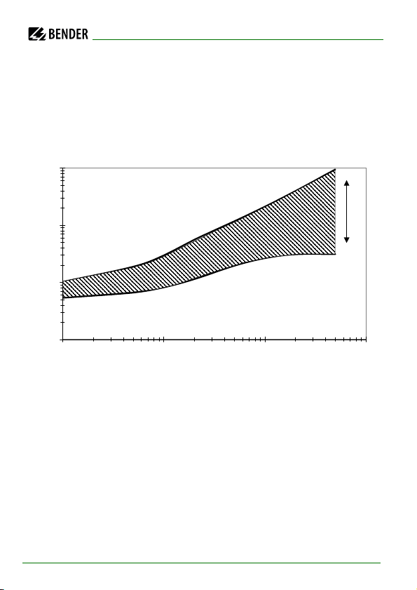
Technical data IRDH375(B)
1
10
100
1000
1 10 100 1000
C
e
[µF]
≤ 10 MΩ
≥
0 kΩ
R
F
t
an
[s]
9.3 Characteristic curves
ISOMETER® response times in relation to system leakage capacitances of:
Ce = 1…500 μF, Un = 0…793 V/50 Hz
84
IRDH375_D00124_05_M_XXEN/01.2020
Page 84
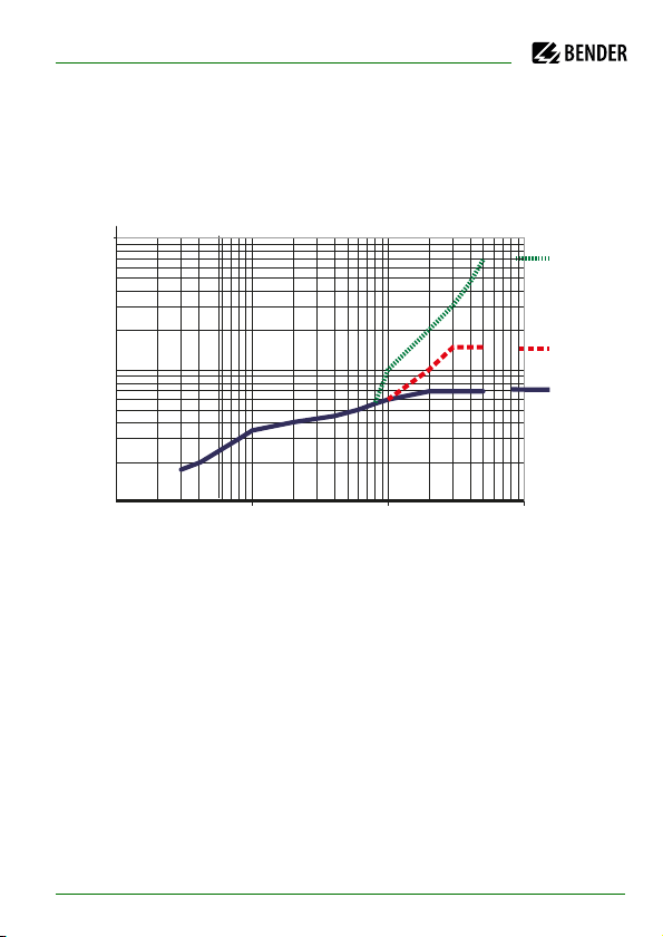
Technical data IRDH375(B)
100
1000
10000
0,1 1 10 100
f
n
[Hz]
U
n
[V]
AGH520S
AGH204S-4
IRDH375
0,3
Max. AC voltage between the IT system and earth in the frequency
range < 50 Hz
IRDH375_D00124_05_M_XXEN/01.2020
85
Page 85
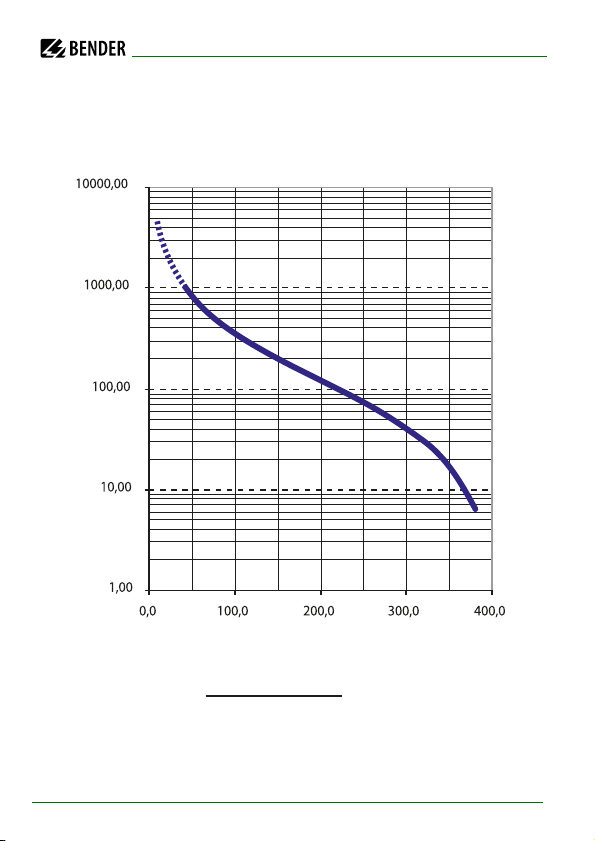
Current output 0…400 µA (only IRDH375)
R
F
[ kW]
I
[ mA]
RF =
400 mA x 120 kW
I
- 120 kW
Technical data IRDH375(B)
RF = Insulation fault in kΩ
I = Current output in μA
86
IRDH375_D00124_05_M_XXEN/01.2020
Page 86
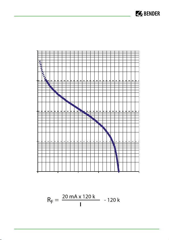
Technical data IRDH375(B)
1
10
100
1000
10 000
0 5 10 15 20 25
I [mA]
R
F
[kW]
Current output 0…20 mA (IRDH375B)
RF = Insulation fault in kΩ
I = Current output in mA
IRDH375_D00124_05_M_XXEN/01.2020
Ω
Ω
87
Page 87
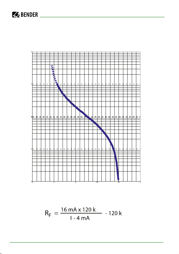
Current output 4…20 mA (IRDH375B)
1
10
100
1000
10 000
0 5 10 15 20 25
I [mA]
R
F
[kW]
Technical data IRDH375(B)
Ω
RF = Insulation fault in kΩ
I = Current output in mA
88
IRDH375_D00124_05_M_XXEN/01.2020
Ω
Page 88
Technical data IRDH375(B)
Value of the respective number
os
iti
on
of
numbers
from the
left
0 = 1 = 2 = 3 = 4 =
1
K1: N/O operation Test K1: N/C operation Test K1: flashing function K1: N/O operation K1: N/C operation
2
K2: N/O operation Test K2: N/C operation Test K2: flashing function K2: N/O operation K2: N/C operation
3
no external coupling AK AGH204S 80K AK AGH520S AK AGH204S 160K AK AGH150W 160K
4
Cemax 1 µF ** Cemax 10 µF ** Cemax 150 µF Cemax 500 µF
5
6
Self test every 24 hours Self test every hour no periodic self test
7
Language German Language English
8
Password protection not
activated
Password protection
activated
9
AMP measuring
principle
DC measuring principle
10
max. filter frequency
0.1Hz **
max. filter frequency 1Hz
**
max. filter frequency
10Hz **
max. filter frequency
50Hz **
11
min. filter frequency
0,1Hz **
min. filter frequency 1Hz
**
min. filter frequency
10Hz **
min. filter frequency
50Hz **
12
BMS mode ** Isodata ** test data **
13
Bus address in the tens
place IRDH375
Value: 5 ... 9
14
Bus address in the units
place IRDH375
Value: 5 ... 9
15
Number of pulses 2-9 **
Value: 5 ... 9
** The parameters marked with two asterisks are settable via the Service menu item! A password is required for that
purpose !
Status number
IRDH375_D00124_05_M_XXEN/01.2020
89
Page 89
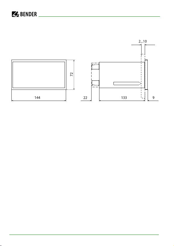
Dimension diagram enclosure IRDH375(B)
All dimensions in mm
panel cut-out 138 x 68 mm
Technical data IRDH375(B)
90
IRDH375_D00124_05_M_XXEN/01.2020
Page 90

Technical data IRDH375(B)
9.4 Ordering details
9.4.1 ISOMETER®
Typ e
IRDH375-435 3NAC 0…793 V
IRDH375W-435 „ „ B91065000W
IRDH375B-435 „ „ B91065004
IRDH375BW-435 „ „ B91065004W
IRDH375-427 3NAC 0…793 V
IRDH375W-427 „ „ B91065002W
IRDH375B-427 „ „ B91065006
IRDH375BW-427 „ „ B91065006W
IRDH375-425 DC 10.2…36V B91065001
IRDH375B-425 B91065005
Nominal voltage
U
n
DC 0…650 V
DC 0…650 V
Supply voltage
U
s
AC 88…264 V
DC 77…286 V
DC 19.2…72 V
Art. No.
B91065000
B91065002
Series …B…
The 375B series provides a BMS interface, a memory with real-time clock and
other features. An overview about these features is shown in the menu structure on page 47 and in the product and function description on page 20.
IRDH375_D00124_05_M_XXEN/01.2020
91
Page 91
Technical data IRDH375(B)
Option "W"
Devices with ending "W" provide improved shock and vibration resistance. A
special varnish of the electronics provides higher resistance against mechanical stress and moisture. This makes the devices suitable for use in ships, on
rolling stock and in seismic environment.
9.4.2 Dust protection
Transparent cover of the front panel for ingress protection against moisture
and dust (IP65).
Type Dimensions Art. N o.
Transparent cover 144 x 72 mm B98060005
92
IRDH375_D00124_05_M_XXEN/01.2020
Page 92
Technical data IRDH375(B)
9.4.3 Coupling devices
Typ e
AGH204S-4 AC 0…1,650 V B914013
AGH520S AC 0…7,200 V B913033
AGH150W-4 DC 0…1,760 V B98018006
Nominal voltage range
U
n
Art. No.
9.4.4 Measuring instruments
Type Measuring range Dimensions Art. No.
7204-1421 0…400 μA 72 x 72 mm B986763
9604-1421 0…400 μA 96 x 96 mm B986764
7204S-1421 0…400 μA 72 x 72 mm B986804
9604S-1421 0…400 μA 96 x 96 mm B986784
9620-1421 0…20 mA 96 x 96 mm B986841
9620S-1421 0…20 mA 96 x 96 mm B986842
IRDH375_D00124_05_M_XXEN/01.2020
93
Page 93

Technical data IRDH375(B)
94
IRDH375_D00124_05_M_XXEN/01.2020
Page 94

INDEX
A
AGH... 37
Alarm LED 1
Alarm LED 2
Alarm messages
Alarm relay K1
Alarm relay K2
Alarm relays, operating principle setting
Approvals
Automatic self test
B
Bender Measuring Device Interface 72
BMS bus, address ranges
BMS Master
BMS Slave
C
Changing the measuring principle 57
Characteristic curves
Characteristics IRDH375(B)
Commissioning flow chart
Commissioning of a BMS network
Coupling devices
Current output 0...400 uA
Current output 0/4...20 mA
42
42
75
35
35
83
57
73
74
- ordering details
- wiring diagram
76
84
19
30
75
93
37
86
88
52
D
Device fault LED 22
Device fault relay K3
Dimension diagram enclosure IRDH375
Directions for installation
Display in the menu mode
Display in the standard mode
E
EDS4...
- Common message
Explanations of symbols and warnings
External coupling devices
External RESET button
External TEST button
F
Factory Settings 77
Fault messages, language setting
Flashing point
Function
Function input F1/F2
H
How to use this manual 7
35
17
44
43
23
56
35
35
65
74
21
26
90
17
IRDH375_D00124_05_M_XXEN/01.2020
95
Page 95

I
INFO key 42
Interconnected systems
ISO monitor (IRDH375B)
IsoData protocol
K
K3, system fault relay 22
M
Measuring instruments 93
Memory database
Menu
- COM SETUP
- HISTORY INFO
- ISO ADVANCED
- ISO SETUP
- LANGUAGE
- PASSWORD
- SERVICE
Menu structure
O
Operating 42
Operating features and displays
Option „W“
19
Ordering details
25
61
68
50
60
51
56
52
65
63
66
49
91
42
R
Real-time clock 25
RESET button
Response values Alarm 1 and Alarm 2 set-
RS-485 interface
RS-485 network
S
Self test, ISOMETER 42
Service
Setting the bus address for IRDH375B
Setting the date (IRDH375B)
Setting the real-time clock (IRDH375B)
Setting the system leakage capacitance
Standards
Status number
system leakage capacitance, setting
T
Technical data IRDH375 79
Terminating resistor
TEST button
Topology RS-485
Training courses
21, 42
ting
52
70
- correct arrangement
- wrong arrangement
8
83
89
70
42
71
10
71
71
60
58
57
58
57
P
Parameterization via Internet 67
Password, activating and setting
Product description
20
96
63
W
Wiring 71
wiring diagram ISOMETER
Work activities on electrical installations
workshops
10
IRDH375_D00124_05_M_XXEN/01.2020
35
13
Page 96

Page 97

Page 98

Page 99

Page 100

 Loading...