


ISOMETER IR427 + MK7
Table of contents
 Loading...
ES EN
CUIDADO
CAUTION
Manual
ISOMETER® IR427 + MK7
Dispositivo de vigilancia de
aislamiento y repetidor de alarma
Uso previsto
El ISOMETER® IR427 controla la resistencia de aislamiento RF de
un sistema de IT médico con 70…264 V de CA. También se controla la corriente de carga y la temperatura del transformador del
sistema de IT. El dispositivo no necesita una tensión de alimentación adicional. La capacidad de derivación de red máxima permi-
es de 5μF. Las alarmas son emitidas al repetidor de alarma
tida C
e
MK7 a través de bus de datos.
El MK7 solo puede utilizarse en combinación con el IR427.
Instrucciones generales de seguridad
Además de estas instrucciones de servicio, las «Instrucciones técnicas de seguridad importantes para productos Bender» adjuntas
también forman parte de la documentación del dispositivo .
Instrucciones de seguridad específicas del dispositivo
En cada sistema galvánicamente unido solo debe
conectarse un dispositivo de vigilancia de aislamiento.
Antes de realizar pruebas de aislamiento y tensión
en la instalación, el dispositivo de vigilancia de
aislamiento debe desconectarse del sistema IT, todo el tiempo que dure la comprobación.
Insulation monitoring device
ENES
and control panel
Intended use
The ISOMETER® IR427 monitors the insulation resistance RF in
medical IT systems of AC 70…264 V. In addition, the IT system
transformer's load current and temperature are monitored. The
device does not require separate supply voltage. The maximum
permissible system leakage capacitance C
put via the alarm indicator and test combination MK7.
MK7 can only be used in combination with IR427.
Safety instructions
Part of the device documentation in addition to this manual is the
enclosed "Safety instructions for Bender products".
Device-specific safety information
Only one insulation monitoring device may be
used in each interconnected system.
When insulation or voltage tests are to be carried
out, the device shall be isolated from the system
for the test period.
is 5 μF. Alarms are out-
e
Descripción del funcionamiento
IR427:
En el modo de funcionamiento normal la pantalla indica la resistencia de aislamiento actual. Con las teclas de desplazamiento
Arriba/Abajo es posible cambiar a % la indicación de la corriente
de carga actual.
Las alarmas se señalan mediante LED y el relé de alarma K1. Además, en los terminales se facilita una señal de bus para el repetidor de alarmas MK7.
Autocomprobación automática
El dispositivo realiza, tras la conexión de la tensión de alimenta-
y posteriormente cada hora, una autocomprobación para
ción U
S
determinar fallos de funcionamiento internos o errores de conexión, los cuales se indican como código de error en la pantalla.
Durante esta operación el relé de alarma no se activa.
Autocomprobación manual
Pulsando la tecla TEST durante más de 2 segundos el dispositivo
realiza una autocomprobación para determinar fallos de funcionamiento internos o errores de conexión, los cuales se muestran
como código de error en la pantalla. Durante esta operación el
relé de alarma se activa.
Mientras se mantiene pulsada la tecla Test se visualizan todos los
elementos de visualización disponibles para este dispositivo.
MK7:
Comprobación manual del IR427 a través del MK7
Pulsando la tecla TEST durante 1 segundo se inicia una autocomprobación del IR427 para determinar fallos de funcionamiento internos. Al mismo tiempo, el MK7 realiza una autocomprobación.
Los avisos de alarma generados a los pocos segundos por la autocomprobación se señalizan mediante los respectivos LEDs del
MK7, véase la ilustración Señalización de alarmas en la página 5.
Con la tecla Mute (zumbador descon.) del MK7 se confirma la alar-
Function
IR427:
In normal operation, the display indicates the currently measured
insulation resistance value.
The Up and Down keys are used to select the display indication of
the currently measured load current in percentages.
Alarms are signalled by the LEDs and the alarm relay K1. In addition, a bus signal is available at the terminals for the alarm indicator and test combination MK7.
Automatic self test
The device automatically carries out a self test after connecting to
the supply voltage U
ternal functional faults or connection faults will be determined
and will appear in form of an error code on the display. The alarm
relay is not switched over during this test.
Manual self test
After pressing the test button for > 2s, a self test is performed by
the device. During this test, functional faults or connection faults
wi ll b e de ter mined and app ear in for m of an e rro r co de on t he d isplay. The alarm relay is switched over during this test.
With the test button pressed and held down, all device-related
display elements appear on the display.
MK7:
Manual test of the IR427 via MK7
After pressing the test button for approx. 1s, the IR427 carries out
a self test. During this test internal functional faults are detected.
In parallel, MK7 also carries out a self test. Alarm messages initiated during the self test are signalled by the respective LEDs of the
MK7 within a few seconds, see figure "Alarm indication" on
page 5. Pressing the buzzer mute button at the MK7 will acknowledge the audible alarm, but the alarm LEDs continue to indicate
and later every hour. During the self test in-
S
IR427-MK7_D00118_00_M_ESEN / 09.2016
1

ISOMETER® IR427 + MK7
Accesorios/
Accessory
1
2
3
ma acústica. La señalización mediante los LED de alarma se mantiene. Tras la realización de la comprobación se apagan los LED de
alarma.
Fallo de funcionamiento (IR427)
Si existe un fallo de funcionamiento, el relé K1 (11, 12, 14) se activa y los 3 LE Ds parpade an. La pantalla mu estra un código de fallo.
E01 = Conexión del conductor de puesta a tierra defectuosa, no
hay una conexión de baja impedancia entre E y KE.
E03 =Interrupción del toroidal de medida de corriente
E04 =Cortocircuito en el toroidal de medida de corriente
E05…Exx = Fallo interno en el dispositivo, contactar el servicio
técnico de la empresa Bender.
Protección por contraseña (IR427)
Si se ha activado la protección por contraseña (ON), los ajustes
sólo pueden realizarse introduciendo la contraseña correcta
(0…999).
Configuración de fábrica FAC (IR427)
Después de activar la configuración de fábrica, todos los ajustes
se restablecen a los valores de fábrica.
Montaje y conexión
¡Riesgo de descarga eléctrico!
Tocar conductores bajo tensión no aislados puede
ocasionar la muerte o daños serios. Evite cualquier contacto físico con conductores activos y
asegúrese de cumplir la normativa para el trabajo
en instalaciones eléctricas.
an alarm. After successful testing, the alarm LEDs go out.
Malfunction (IR427)
In case of a malfunction, the relay K1 (11, 12, 14) and all of the
three LEDs flash. An error code appears on the display.
E01 = PE connection fault, no low-resistance
connection between E and KE.
E03 =Measuring current transformer interruption
E04 =Short-circuit measuring current transformer
E05…Exx = Internal device error, contact the Bender service
Password protection (IR427)
If the password protection has been activated (on), settings can
only be carried out when the correct password (0…999) has been
entered before.
Factory setting FAC (IR427)
After activating the factory setting, all settings previously
changed are reset to delivery status.
Installation and connection
Risk of fatal injury from electric shock!
Touching live parts of the system carries the risk of
electric shock. Before fitting the enclosure and
working on the device connections, make sure
that the power supply has been disconnected and
the system is dead. Observe the installation rules
for live working.
– A continuación se muestra el montaje del IR427 sobre
una regleta de montaje conforme a IEC 60715 o un
montaje atornillado.
– Montaje atornillado de MK7 mediante caja empotrada,
véase el dibujo. Para la rotulación del MK7 hay que desprender el portaetiquetas del bastidor de montaje (cierre de velcro adhesivo)
– The IR427 is suitable for DIN rail mounting acc. to IEC
60715 or for screw mounting, as described below.
– Screw mounting of the MK7 by means of a cavity-wall-
box, see drawing. For labelling the MK7, the label
holder has to be loosened respectively detached from
the mounting frame (hook-and-pile fastener).
Flush-mounting box Ø 66, Drilling hole Ø 70
Caja empotrada Ø 66, perforación Ø 70
60 mm
Distance screw mounting/
Distancia montaje con tornillos
Cavity-wall-box Ø 67, Drilling hole Ø 68
Cajetines de pared Ø 67, perforación Ø 68
60 mm
2
Distance screw mounting/
Distancia montaje con tornillos
IR427-MK7_D00118_00_M_ESEN / 09.2016
ISOMETER® IR427 + MK7
90 mm
45
67,5
36 mm
31,1
47,5
70,5
MK7
on
off
1
234
1
2
24 V
0 V
3
4
34
12
RS485
on
off
R
L
N
J-Y(St)Y 2x2x0,6
IR427
STW2
R
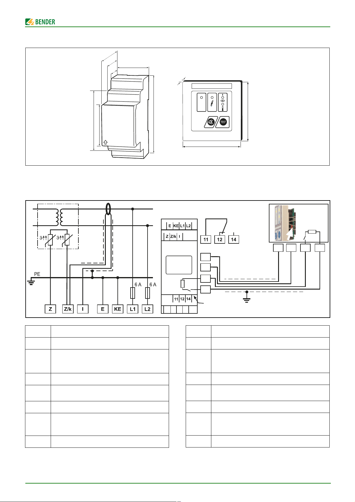
Dimensiones
Esquema de conexiones
Conecte el dispositivo conforme al esquema de conexiones
¡Los cables a KE y E deben tenderse por separado!
Dimensions
10
ON
80
80 mm
Wiring diagram
Connect the device according to the wiring diagram.
The leads to KE and E have to be run separately!
Terminal Conexiones
E, KE Conexión separada de E y KE a PE
Conexión al sistema de IT vigilado;
L1, L2
tensión de alimentación US (véase la etiqueta del
equipo) mediante fusible 6 A
Z, Z/k Conexión al sensor de temperatura (PTC)
Z/k, l
Conexión al toroidal de medida de corriente
(STW2)
1, 2
s
para repetidor de alarma MK7
U
Interfaz RS-485,
3, 4
Terminar la conexión con interruptor R (on/off) si el
dispositivo está conectado al final del bus
11, 12, 14 Relé de alarma K1
IR427-MK7_D00118_00_M_ESEN / 09.2016
Terminal Connections
E, KE Separate connection of E and KE to PE
Connection to the IT system to be monitored;
L1, L2
supply voltage U
(see nameplate) 6 A fuse recom-
S
mended.
Z, Z/k Connection to temperature sensors (PTC)
Z/k, l
11, 12, 14 Alarm relay K1
Connection to the measuring current transformer
(STW2)
1, 2
S
for alarm indicator and test combination MK7
U
RS-485 interface;
3, 4
Terminate the connection with switch R (on, off) if
the device is connected at the end of the bus
3

ISOMETER® IR427 + MK7
ON AL1 AL2
TEST
MENU
> 2s
ON
Puesta en funcionamiento
Antes de la puesta en funcionamiento es necesario controlar la
conexión correcta del ISOMETER®
Realice una comprobación de funcionamiento
mediante un fallo de aislamiento real R
tierra, si fuera necesario mediante una resistencia
.
contra
F
Commissioning
Prior to commissioning, check proper connection of the
ISOMETER®.
It is recommended to carry out a functional test
using a genuine earth fault, e.g. via a suitable resistance !
adecuada para ello.
Todos los MK7 conectados con el dispositivo de vigilancia de aislamiento deben comprobarse mediante autocomprobación manual.
Para este fin, pulse la tecla Test del MK7 para iniciar una prueba
de funcionamiento. Como consecuencia se iluminan todos los
All MK7 panels connected to the IR427 have to be checked by
performing a manual self test.
Press the test button at the MK7 to start a functional test. All LEDs
will light and an audible alarm will sound. If no fault exists, the de-
vice will return to the standard mode after approximately 10 s.
LEDs y suena una señal acústica. Si no hay ningún fallo, el dispositivo cambia de nuevo al modo de funcionamiento estándar después de unos 10 segundos.
Elementos de indicación y manejo IR427
Ele-
mento
Func ión
Frontal del dispositivo/
Front of the device
Display and operating elements IR427
Ele-
ment
ON LED de funcionamiento, verde ON Power On LED, green
AL1
AL2
189 kΩ
Te st
El LED de alarma 1 se ilumina (amarillo):
Valor medido por debajo del valor de respuesta R
an
El LED de alarma 2 se ilumina (amarillo):
Se ha excedido el valor de respuesta % I y °C
Indicación en el modo de funcionamiento
estándar:
Punto parpadeante = ciclo de medición
Resistencia de aislamiento R
= 189 kΩ
F
Tecla Test: Inicio de una autocomprobación (2 s);
Tecla Arriba: Puntos del menú/valores
189 kΩ
LED Alarm 1 lights (yellow):
AL1
Measured value has fallen below the
response value Ran;
AL2
LED Alarm 2 lights (yellow):
Response value % I and °C exceeded
Display in standard mode:
Flashing point = measuring pulse
Insulation resistance R
Te st TEST button: to start a self test (2 s);
UP key: Menu items/values
Functio n
= 189 kΩ
F
Tecla abajo: Puntos del menú/valores DOWN key: Menu items/values
Inicio del modo de menú (2 s);
MENU
Tecla Intro: (< 1,5 s) punto de menú, punto
de submenú, confirmar valor.
(2 s) volver al nivel del menú inmediatamente superior
Elementos de indicación y manejo MK7
Ele-
mento
ON LED de funcionamiento, verde ON Power On LED, green
El LED de fallo de aislamiento se ilumina
(amarillo):
Valor medido por debajo del valor de respuesta R
an
El LED de sobrecarga (sobrecorriente) se ilumina (amarillo):
Se ha excedido el valor de respuesta I
El LED de sobretemperatura se ilumina (amarillo):
Valor medido por encima del valor de respuesta °C
Tecla Mute: Desconectar la alarma acústica Mute button: to cancel the alarm
Función
alarm
Display and operating elements MK7
Gerätefront/
Front of the device
ON
MENU To start the menu mode (2 s) ;
ENTER key: (< 1.5 s) To confirm menu item,
submenu item and value.
(2 s) To return to the next higher menu level
Ele-
ment
Function
LED insulation fault lights (yellow):
Measured value has fallen below the
response value R
an
LED overload (overcurrent) lights (yellow):
response value I
alarm
exceeded
LED overtemperature lights (yellow):
response value °C exceeded
TEST Iniciar la autocomprobación TEST Starting the self test
4
IR427-MK7_D00118_00_M_ESEN / 09.2016
Loading...