

Bender iso685-S-B-CN, iso685-DCN, iso685-W-S-B-CN, iso685-W-D-CN, iso685-W-D-P-CN Quick Start Manual
...Page 1
CN EN
DANGER
CAUTION
108 mm
110 mm
m
m
39
IT-System
1x
1/2
1x
Iso.FehlersucheIso.Fehlersuche
43 s
PGH ON
IT System
OK
230 kΩ
R(an) 40kΩ/10kΩ
OK
230 kΩ
iso685(W)-D, iso685(W)-D-B-CN
iso685(W)-D-P-CN:
绝缘故障定位 /insulation fault locati
危险
警告
快速操作手册 / Quick-start guide
ISOMETER® iso685...-CN
绝缘监视仪
CN EN
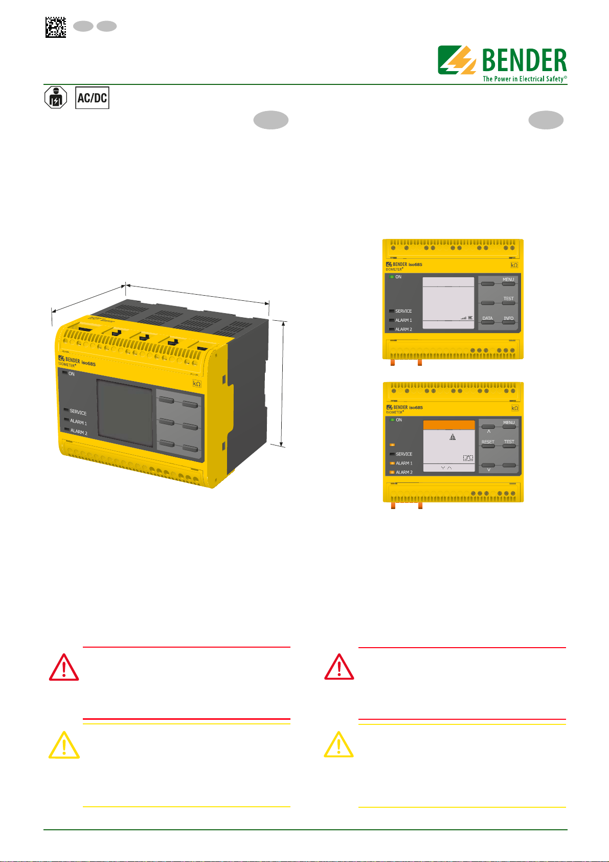
这本快速入门指南适用于下列型号 : iso685-D-CN, W-D-CN,
-S-CN, W-S-CN, D-B-CN, S-B-CN, W-S-B-CN, -D-P-CN, W-DP-CN, -S-P-CN, W-S-P-CN. 设备带有 -S 后缀的没有显示,因
此需要一个外部显示设备。操作类似于对应的带有显示iso685
变形。
这本快速入门手册不能替代操作手册。你可以在我们的主页
www.bender.de/manuals 上找到操作手册。
Insulation monitoring device
This quick-start guide applies to the following devices: iso685-DCN, W-D-CN, -S-CN, W-S-CN, D-B-CN, S-B-CN, W-S-B-CN, -D-P-CN,
W-D-P-CN, -S-P-CN, W-S-P-CN. Devices with the suffix -S do not
have a display and therefore need an external display. The operation is similar to the corresponding iso685 variants with display.
This quick-start guide does not replace the operating manual,
which can be found on our homepage under www.bender.de/
manuals.
使用目的
ISOMETER® 监视不接地交直流主回路(IT 系统)的绝缘电阻,
主回路电压 AC, AC/DC 0…690 V 或 DC 0…1000 V。
出现在 AC/DC 系统中的直流组件不会影响操作特性。独立的电
源电压允许断开被监视系统。最大允许的系统泄露电容是1000
µF, 这取决于应用特定的配置。
安全介绍
电击危险 !
端子携带高电压并且直接接触端子可能会导致触
。
如果设备的端子直接连接到通电的 IT 系统 ,
电
端子 E 和 KE 不必从 PE 线断开
。
由于安装不正确而导致损坏的风险 !
连接多个绝缘监视仪可能会导致安装损坏。此外,
如果连接超过一台绝缘监视仪,设备将不起作用,
。
并不会发出绝缘故障警报
Intended use
The ISOMETER® monitors the insulation resistance of unearthed
AC/DC main circuits (IT systems) with mains voltages of AC, AC/
DC 0…690 V or DC 0…1000 V.
DC components existing in AC/DC systems do not influence the
operating characteristics. A separate supply voltage allows deenergised systems to be monitored. The maximum permissible
system leakage capacitance is 1000 μF, dependent on the application-specific profile.
Safety instructions
Risk of electric shock!
The terminals carry high voltage and direct contact with
these terminals will likely result in electrocution. If the
terminals L1/+, L2, L3/- of the device are connected to a
live IT system, the terminals E and KE must not be
disconnected from the protective conductor (PE).
Risk of damage to property due to incorrect
installation!
Connecting more than one insulation monitoring device may result in damage to the installation. In addition, the device will not function and will not report an
insulation fault if more than one insulation monitoring
device is connected.
iso685_D00022_06_Q_CNEN/10.2016
1
Page 2
ISOMETER® iso685...-CN
CAUTION
DANGER
CAUTION
WARNING
警告
螺丝安装
/ Screw mounting
导轨安装 / DIN rail mounting
72 mm
108 m m
54 mm
100 m m
107.3 mm
危险
警告
提醒
与IT 系统断开!
在装置进行绝缘或者电压测试之前,绝缘监视仪必
。
须与 IT 系统断开,并且保证测试持续时间
设备可能会损坏
。
否则,
安装
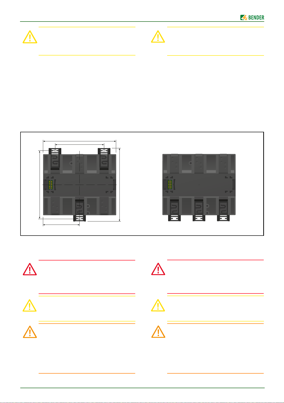
考虑相邻设备的最小距离:侧面 0 毫米,顶部 20 毫米,底部
20 毫米!
导轨安装 :
每个设备需要 3 个安装夹(其中的 2 个为独立包装),安装在
DIN 导轨上,保证安全和安装紧固。
螺丝安装
手动或者使用工具安装 3 个配套的安装夹 (2 个为一组单独
包装),安装夹伸出外壳。通过三个 M4 螺丝装置固定装置(无
沉头螺钉)如下图所示。
Disconnect from the IT system!
The insulation monitoring device must be disconnected
from the IT system before insulation or voltage tests at
the installation and must remain so for the duration of
the test. Otherwise the device may be damaged.
Installation
Consider a minimum distance to adjacent devices: lateral 0 mm,
top 20 mm, bottom 20 mm!
DIN rail mounting:
Snap all 3 mounting clips delivered with the device (2 of them
packed separately) onto the DIN rail in such a way that a safe and
tight fit is ensured.
Screw mounting
Install the three accompanying mounting clips (2 of them are
packed separately) manually or by means of a tool in a way that
they protrude beyond the enclosure. Fix the device by means of
three M4 screws (no counter sunk screw) as shown in the following pictures.
连接
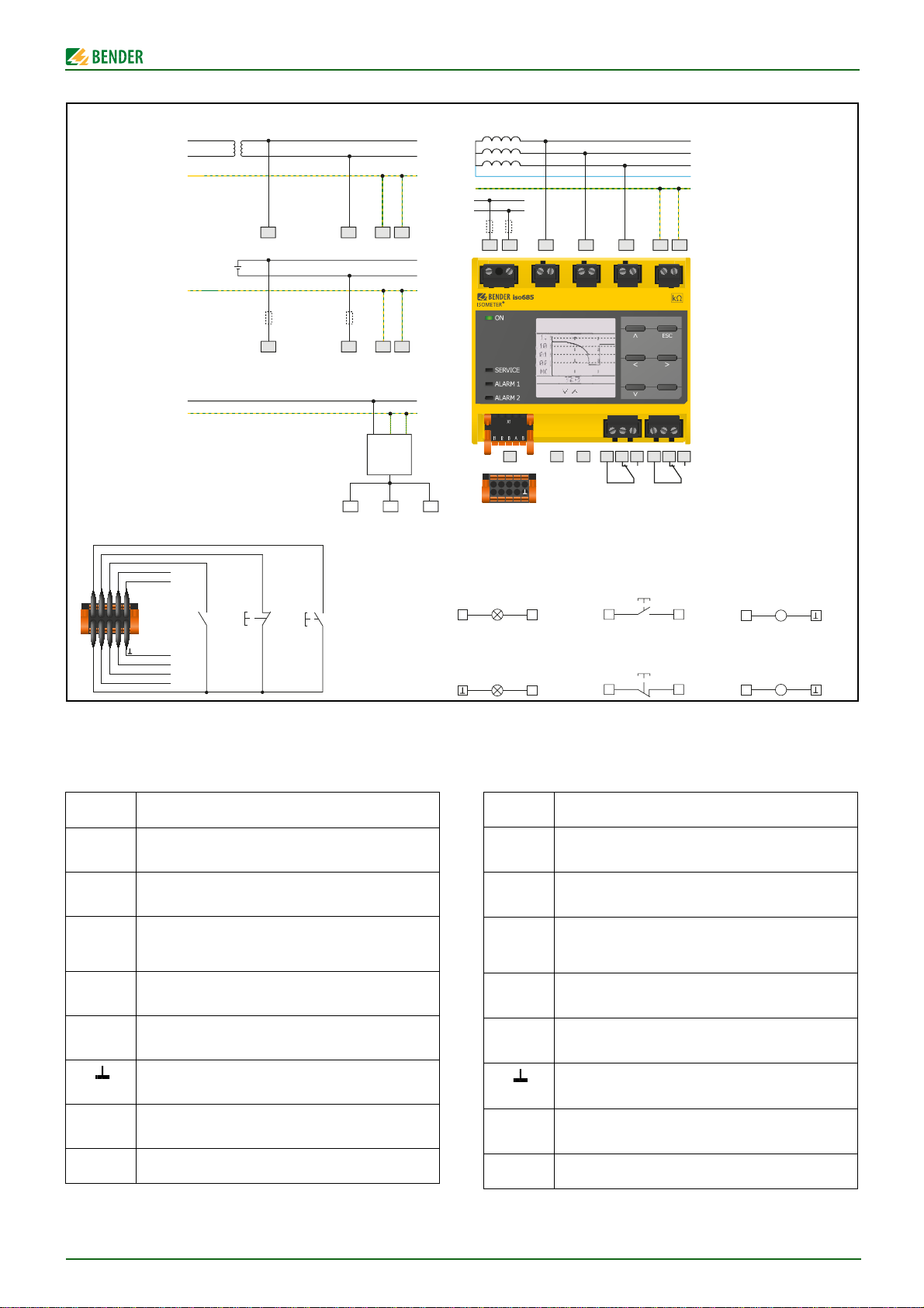
根据设备的接线图对设备进行布线,请参考技术参数。连接装
置后,安装上、下端子盖板 !
电击危险 !
额定电压上升至 1000V 的电压可能瞬间出现在端子
。
L1/+…L3/–上
用设备之前,确保已经正确安装端子盖板
应用线路保护 !
直接接触可能会引起触电。 在 使
。
符合标准 DIN VDE 0100-430,线路保护将用于电源
电压
。
由于短路造成的伤害、火灾和设备损坏!
当耦合端子 L1/+, L2, L3/- 连接到≤ 690 V 的被
监视IT 系统时,设备防止短路就必须符合标准 IEC
60364-4-43:2008,如果采用这样的接线方式,可
。
以把短路风险降到最低
故障检验的接线方式
推荐采用短路检验和接地
。
Connection
Wire up the device according to the wiring diagram taking account of the technical data. After connecting the device, install
the enclosed upper and lower terminal cover!
Risk of electric shock!
A nominal voltage of up to 1000 V may be present at the
terminals L1/+…L3/–. Direct contact with these will
likely result in electrocution. Make sure the terminal
covers are properly mounted and clicked in before
putting the device into operation.
Apply line protection!
According to DIN VDE 0100-430 a line protection shall
be provided for the supply voltage.
Danger of injury, fire and damage to property due to
a short circuit!
When coupling the terminals L1/+, L2, L3/- to the IT system ≤690 V to be monitored, devices for protection
against a short-circuit can be omitted according to
IEC 60364-4-43:2008 if the wiring is carried out in such a
way as to reduce the risk of a short-circuit to a minimum. The use of short-circuit proof and earth-fault
proof wiring is recommended.
2
iso685_D00022_06_Q_CNEN/10.2016
Page 3
ISOMETER® iso685...-CN
I1
I2
I3
A
B
M+
Q2
Q1
+
L1
L2
L3
N
PE
U
S
A1/+ A2/-
11RETHX1 12 14 21 22 24
L1/+
L2 L3/- KE E
L1/+ L3/- KE E
L1/+ L3/- KE E
L1
L2
PE
L+
L-
PE
1
87
AC
3(N)AC
DC
I1 I2 I3 A B
Q1+Q2 M+
X1
AGH 520S
L1/+
L2 L3/-
U > 690 V AC
U > 1000 V DC
n
n
PE
IT-System
Data-isoGraph 2
1/3
Stunde 16:52
Data-isoGraph 2
1/4
1,0
,10 0
,010
,00 1
MΩ
Stunde 16:26 16:52
Q
x
X1
+
Q
x
X1
+I
X1
+I
x
X1
M
+
X1 X1
A
M
+
X1 X1
V
Passive
被动的
Active
主动的
Active high
高电平
x
Active low
低电平
Current output
电流输出
Voltage output
电压输出
X1
X1 X1
X1
数字输入
数字输出
模拟输出
线路图举例 X1
无效的
设备
重置
测试
*
*
(iso685(W)-D/-S)
举例
/ Example
/ Digital outputs
/ Digital inputs
/ Analogue
outputs
/
Deactivate
device
/ Reset
/ Test
/ Wiring example X1
接线图
Wiring diagram
* 对于 > 690 V 的系统和过电压 III 类,需要有保险丝连接
到系统中并且进行监视。 推荐 : 2 A 保险丝。
连接到端子图
端子 连接
I1…I3
(X1)
A, B
(X1)
(X1)
Q1, Q2
(X1)
M+
(X1)
(X1)
RJ45
(ETH)
iso685_D00022_06_Q_CNEN/10.2016
可配置的数字输入 ( 例如:测试、重置 )。
串行接口 RS-485,
通过 DIP 开关 R (OFF, ON) 操作。
输入和输出 I,Q 和 M 的电源电压。
+
电气过负载保护。 在短路和瞬变 ( 可重置 ) 的情
况下自动关闭。
可配置数字输入
可配置的模拟输出
( 例如:测量仪器 )
参考的电位接地
以太网连接
R
可调终端电阻器
* For systems > 690 V and with overvoltage category III a fuse for
the connection to the system to be monitored must be provided.
Recommendation: 2 A fuses.
Legend to terminal diagram
Terminal Connections
I1…I3
(X1)
A, B
(X1)
(X1)
Q1, Q2
(X1)
M+
(X1)
(X1)
RJ45
(ETH)
Configurable digital inputs (e.g. Test, Reset).
Serial interface RS-485,
termination by means of a DIP switch R (OFF, ON).
•Supply voltage of the inputs and outputs I, Q and M.
+
•Electrical overload protection. Automatic shutdown in
the event of a short circuit and transient (resettable).
Configurable digital output
Configurable analogue output
(e.g. measuring instrument)
Reference potential ground
Ethernet connection
R Switchable terminating resistor
3
Page 4
ISOMETER® iso685...-CN
启动
该配置文件 “ 电源电路 ” 适用于大部分 IT 系统 .
更加详细的配置,请参考操作手册。
直到启动过程完成后,继电器断电。
设备的启动
1. 检查 ISOMETER® 是否正确的连接到被监视系统上。
2. 绝缘监视仪 ISOMETER® 连接电源电压。
3. 连接主电压。
4. 当 ISOMETER® 在闭合主电压后进行首次操作,会有启动
向导指导您如何一步步的进行启动。关于重启,可以通过
设备菜单手动打开启动向导。执行启动向导并且完成所要
求的设置。
5. 设备在 4 个步骤内完成自检。当然,在这个测试过程中不
会检查报警继电器。完成自检后,测量的绝缘阻值会显示
在液晶屏上。如果值超过液晶屏底部显示的响应值,会显
示 “OK”。如果在自检过程中有故障,在液晶屏上会显
示故障信息。
使用绝缘故障来检查这项功能。检查被监视系统的
ISOMETER® ,例如使用合适的对地电阻。
Commissioning
The profile "power circuits" is suitable for most of the IT
systems. For a description of the profiles refer to the
manual.
The relays are de-energised until the commissioning
process is finished.
Commissioning of the device
1. Check that the ISOMETER® is properly connected to the
system to be monitored.
2. Connect the supply voltage to the ISOMETER®.
3. Connect the mains voltage.
4. When the ISOMETER® is operated for the first time after
switching on the mains voltage, a commissioning wizard
appears on the display that guides you through the commissioning process step by step. For recommissioning, the commissioning wizard can be opened manually via the device
menu.
Execute the commissioning wizard and carry out the required
settings.
5. The device carries out a self test in four steps. However, the
alarm relays are not checked during this test. After completion of the test, the measured insulation resistance is shown
on the display. If the value exceeds the response values indicated in the lowest line of the display, the message "OK" will
additionally be displayed. If a fault is detected during the self
test, a fault message will appear on the display.
Check the function using a genuine insulation fault. Check the
ISOMETER® in the system being monitored, e.g. using a suitable
resistance against earth.
启动带绝缘监视仪的 ISOMETER®s iso685…-P-CN (EDS)
6. 把 ISOMETER® 置入之前描述的操作中。
7. 把 EDS 置入其文件描述的操作中。
8. 为 ISOMETER® 和每个 EDS 设置不同的总线地址。
9. 停用所有 EDS 的测量通道,保证没有电流互感器连接。
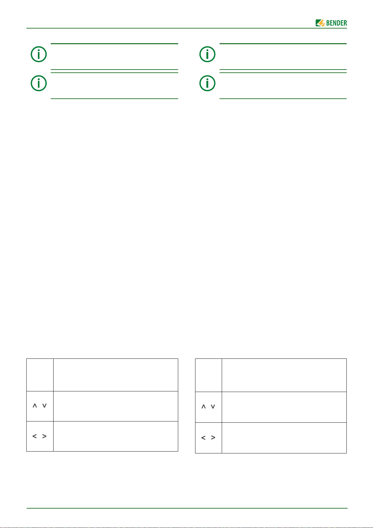
根据向导,在菜单和参数设置中使用下面所示的按钮。
MENU
ESC
OK
启动菜单
1x 避开操作步骤,返回
>1x 停止启动向导
确认回车
UP 按钮 : 在菜单中向上移动,
增加值。
DOWN 按钮 : 在菜单中向下移动 ,
减少值。
向左箭头按钮 : 返回上一级菜单,
选择一个部分。
向右箭头按钮 : 往下一级菜单,
选择一个部分。
Commissioning of the ISOMETER®s iso685…-P-CN with an
insulation monitoring device (EDS)
1. Put the ISOMETER® into operation as described before.
2. Put the EDS into operation as described in the respective
documentation.
3. Set different bus addresses for the ISOMETER® and each EDS.
4. Deactivate all measuring channels of the EDS to which no transformer is connected.
To navigate within the menu and for parameter setting use the
buttons illustrated below.
MENU
ESC
Start the menu
1x Escape from the operating step, back
>1x Stop commissioning wizard
OK
Confirm entry
UP button: to move up in the menu,
increase the value.
DOWN button: to move down in the menu,
decrease the value
Left arrow button: back in the menu,
to select a section.
Right arrow button: to go to the next menu,
select a section
4
iso685_D00022_06_Q_CNEN/10.2016
Page 5
ISOMETER® iso685...-CN
报警和它的影响
报警的原因
• 绝缘故障
绝缘电阻有下列 2 组响应值
LEDs ALARM 1 ALARM 2
• 设备故障
闪烁。
LED SERVICE 闪烁。
• 激活绝缘故障定位
LED PGH ON 在故障电流通道闪烁。
设备信号报警或设备故障
• 显示指示的错误以及应用的测量值。
• 在发生 "ALARM 1" 或 "ALARM 2" 的情况下,相关 LED 等闪
烁。
• 如果分配,会间隔发出报警哔哔声。
• 开关分配的报警继电器。
• 开关分配的数字输出。
重置报警信息 ( 重置 )
要求 : 不再存在报警的原因。 绝缘电阻必须至少高于响应值
25 % 。
选择 : "RESET" > "RESET" > "OK".
技术数据
( )* = 出厂设置
绝缘协调性 (IEC 60664-1/IEC 60664-3)
额定电压
过电压分类 (OVC) .................................................................................................................................III
额定脉冲电压 (IEC 60664-1) ....................................................................................................... 8 kV
额定绝缘电压 (IEC 60664-1) .................................................................................................. 1000 V
污染等级 (U
污染等级 (U
保护隔离介于 (≤ 2000 m NN) 和 .........................................................(L1/+,L2,L3/-) 之间 –
........................................................................ (A1,A2) – (11,12,14) – (21,22,24) – (E, KE), (X1, ETH, X3, X4)
电压测试、常规测试 (IEC 61010-1) .......................................................................... AC 2.2 kV
电源电压
电源电压范围 U
U
s
U
s
功耗,典型地 50 Hz (400 Hz)........................................................... ≤12 W/21 VA (≤12 W/45 VA)
被监视的 IT 系统
标称系统电压范围
U
n
U
n
响应值
响应值
响应值 R
操作的不确定性 ( 符合 IEC 61557-8)...................相关的配置 , ±15 %, min. ±1 kΩ
时间相应
响应时间
符合 IEC 61557-8 .............................................................................. 相关的配置 , 典型 4 s
测量回路
测量电压
测量电流 I
内部电阻 R
允许外部直流电压 U
允许系统泄露电容 C
接口
现场总线 : 接口 / 协议
..........................................................................................................................................1000 V
< 690 V) .......................................................................................................................... 3
n
< 1000 V) ........................................................................................................................ 2
n
.................................................................................................. AC/DC 24…240 V
的公差 ............................................................................................................................. -20…+15 %
s
的频率范围 ........................................................................................................... DC, 50…400 Hz
Un .................................................................. AC 0…690 V, DC 0…1000 V
的公差 ..............................................................................................................................AC/DC +15 %
的频率范围 ............................................................................................................. DC, 1…460 Hz
R
(Alarm 1) ......................................................................................... 1 kΩ…10 MΩ (40 kΩ)*
an1
(Alarm 2) ......................................................................................... 1 kΩ…10 MΩ (10 kΩ)*
an2
t
在 R
= 0.5 x Ran (Ran= 10 kΩ) 和 Ce= 1 μF
an
F
Um ................................................................................. 相关的配置 , ±10 V, ±50 V
.................................................................................................................................≤ 403 μA
m
, Zi.............................................................................................................................≥ 124 kΩ
i
.....................................................................................................≤ 1200 V
fg
............................................. 取决于相关配置 , 0…1000 μF
e
....................................................... web server/Modbus TCP/BCOM
Alarm and its effect
Cause of the alarm
• Insulation fault
The insulation resistance is below both response values
LEDs ALARM 1 and ALARM 2 flash.
• Device error
LED SERVICE flashes.
• Active insulation fault location
LED PGH ON blinks according to the locating current.
Device signals alarm or device error
• Display indicates error and, where applicable,
the measured value.
• In the event of "ALARM 1" or "ALARM 2", the associated LEDs
flash.
• A warning sound beeps at intervals, if assigned.
• Assigned alarm relays will switch.
• Assigned digital outputs will switch.
Reset alarm messages (Reset)
Requirement: The cause of the alarm is no longer present. The insulation resistance must be at least 25 % higher than the response value.
Select: "RESET" > "RESET" > "OK".
Technical data
( )* = factory setting
Insulation co-ordination (IEC 60664-1/IEC 60664-3)
Rated voltage ............................................................................................................................................. 1000 V
Overvoltage category (OVC) ...............................................................................................................................III
Rated impulse voltage (IEC 60664-1) .......................................................................................................... 8 kV
Rated insulation voltage (IEC 60664-1) ................................................................................................... 1000 V
Pollution degree (U
Pollution degree (U
Protective separation (≤ 2000 m NN) between......................................................................(L1/+,L2,L3/-) –
........................................................................(A1,A2) – (11,12,14) – (21,22,24) – (E, KE), (X1, ETH, X3, X4)
Voltage test, routine test (IEC 61010-1) ............................................................................................. AC 2.2 kV
Supply voltage
Supply voltage range Us....................................................................................................... AC/DC 24…240 V
Tolerance of U
Frequency range of U
Power consumption typically 50 Hz (400 Hz)..................................................≤12 W/21 VA (≤12 W/45 VA)
IT system being monitored
Nominal system voltage range Un ..................................................................... AC 0…690 V, DC 0…1000 V
Tolerance of U
Frequency range of U
Response values
Response value R
Response value R
Operating uncertainty (acc. to IEC 61557-8) ......................................profile-dependent, ±15 %, min. ±1 kΩ
Time response
Response time tan at RF = 0.5 x Ran (Ran= 10 kΩ) and Ce= 1 μF
acc. to IEC 61557-8 .................................................................................................. profile-dependent, typ. 4 s
Measuring circuit
Measuring voltage Um .................................................................................. profile dependent, ±10 V, ±50 V
Measuring current I
Internal resistance R
Permissible extraneous DC voltage U
Permissible system leakage capacitance C
Interfaces
Field bus:Interface/protocol.............................................................................. web server/Modbus TCP/BCOM
< 690 V) .......................................................................................................................... 3
n
< 1000 V) ........................................................................................................................ 2
n
............................................................................................................................. -20…+15 %
s
............................................................................................................. DC, 50…400 Hz
s
...............................................................................................................................AC/DC +15 %
n
............................................................................................................... DC, 1…460 Hz
n
(Alarm 1) .................................................................................... 1 kΩ…10 MΩ (40 kΩ)*
an1
(Alarm 2) .................................................................................... 1 kΩ…10 MΩ (10 kΩ)*
an2
.............................................................................................................................≤ 403 μA
m
, Zi..........................................................................................................................≥ 124 kΩ
i
.................................................................................................≤ 1200 V
fg
........................................ dependent on the profile, 0…1000 μF
e
iso685_D00022_06_Q_CNEN/10.2016
5
Page 6
ISOMETER® iso685...-CN
开关元件
开关元件
操作原理
额定工况下的电气耐久性
接触器数据符合
................................................................................................................ 2 组转换触点
......................................................................................... 常开操作 */ 常闭操作
............................................................................. 10 000 周期
IEC 60947-5-1
适用类别................................................................................................. AC-13AC-14DC-12DC-12DC-12
额定操作电压 ...................................................................................... 230 V230 V 24 V 110 V 220 V
额定操作电流 .................................................................................................... 5 A3A 1 A 0,2 A 0,1 A
额定绝缘电压 ≤2000 m NN ...................................................................................................... 250 V
额定绝缘电压 ≤3000 m NN ...................................................................................................... 160 V
最小接触率...................................................................................................... 1 mA 在 AC/DC ≥10 V
其他
EMC ........................................................................................................................................... IEC 61326-2-4
保护等级,内置组件 (DIN EN 60529) ............................................................................... IP40
保护等级,端子 (DIN EN 60529) ............................................................................................ IP20
1
) 这是一个 A 类产品。 在德国,这种产品可能会引起无线电
干扰。在这种情况下,用户可能需要采取纠正措施。
ISOMETER® 设计符合如下标准 :
DIN EN 61557-8 , DIN EN 61557-9 (iso685…-P-CN).
快速操作手册是有效的
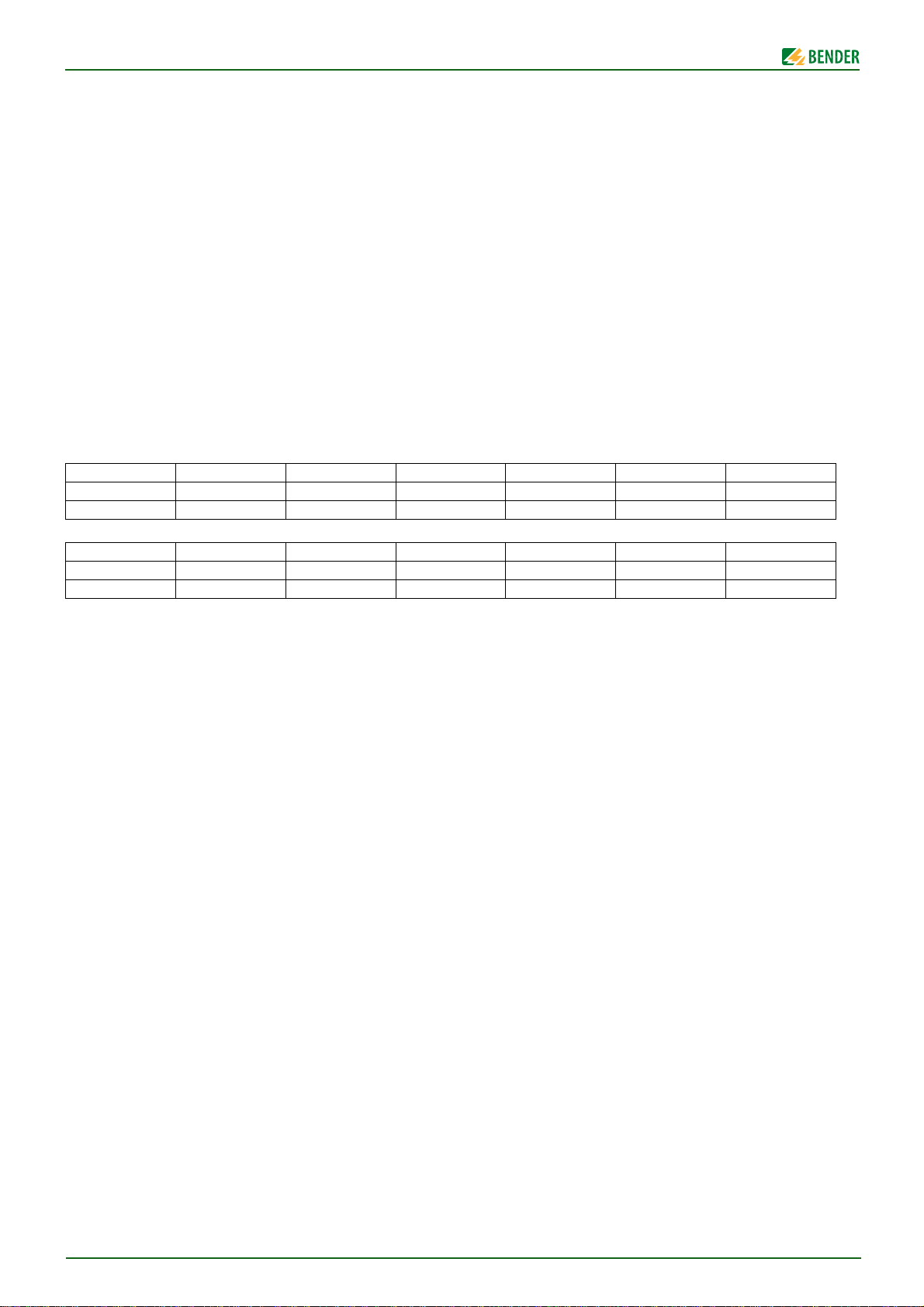
型号 / Type
订货号 /Art. No.
显示 / Display
iso685-D-CN iso685W-D-CN iso685-S-CN iso685W-S-CN iso685-D-B-CN iso685W-D-B-CN
B91067011CN B91067011WCN B91067111CN B91067111WCN B91067021CN B91067021WCN
XX - - XX
Switching elements
Switching elements ......................................................................................................... 2 changeover contacts
Operating principle ............................................................................................. N/C operation*/N/O operation
Electrical endurance under rated operating conditions..................................................................10 000 cycles
Contact data acc. to IEC 60947-5-1
Utilisation category ............................................................................................AC-13AC-14DC-12DC-12DC-12
Rated operational voltage ................................................................................... 230 V230 V 24 V 110 V 220 V
Rated operational current ................................................................................................. 5 A3A 1 A 0,2 A 0,1 A
Rated insulation voltage ≤2000 m NN .......................................................................................................250 V
Rated insulation voltage ≤3000 m NN .......................................................................................................160 V
Minimum contact rating .................................................................................................. 1 mA at AC/DC ≥10 V
(1
Other
EMC ........................................................................................................................................... IEC 61326-2-4
Degree of protection, built-in components (DIN EN 60529) ....................................................................... IP40
Degree of protection, terminals (DIN EN 60529) ......................................................................................... IP20
1)
This is a class A product. In a domestic environment, this product may cause radio interference. In this case, the
user may be required to take corrective actions.
The ISOMETER® has been developed in compliance with the following standards:
DIN EN 61557-8 , DIN EN 61557-9 (iso685…-P-CN).
(1
This quick-start guide is valid for:
型号 / Type
订货号 /Art. No.
显示 / Display
iso685-S-B-CN iso685W-S-B-CN iso685-D-P-CN iso685W-D-P-CN iso685-S-P-CN iso685W-S-P-CN
B91067121CN B91067121WCN B91067031CN B91067031WCN B91067131CN B91067131WCN
--XX--
6
iso685_D00022_06_Q_CNEN/10.2016
Page 7
ISOMETER® iso685...-CN
iso685_D00022_06_Q_CNEN/10.2016
7
Page 8
ISOMETER® iso685...-CN
All rights reserved.
Reprinting only with permission
of the publisher.
Subject to change!
© Bender GmbH & Co. KG
服务
服务热线 : 0700-BenderHelp (Telephone and Fax)
Carl-Benz-Straße 8 • 35305 Gruenberg • Germany
电话 : +49 6401-807-760 • 传真 : +49 6401 807-629
电子邮件 : [email protected] • www.bender.de
8
保留版权。
复制和转载
必须由出版商认可。
修改受管制 !
© Bender GmbH & Co. KG
Bender GmbH & Co. KG
Postfach 1161 • 35301 Grünberg • Germany
Londorfer Str. 65 • 35305 Grünberg • Germany
iso685_D00022_06_Q_CNEN/10.2016
文件
 Loading...