


Operation Manual
BSH5000
myBlock Dry Bath Incubator

Contents
CHAPTER 1 INTRODUCTION ------------------------------- ERROR! BOOKMARK NOT DEFINED.
CHAPTER 2 SPECIFICATIONS ----------------------------- ERROR! BOOKMARK NOT DEFINED.
1. AMBIENT OPERATING ENVIRONMENT: --------- ERROR! BOOKMARK NOT DEFINED.
2. TECHNICAL DATA ----------------------------- ----------- ERROR! BOOKMARK NOT DEFINED.
CHAPTER 3 OVERVIEW ----------------------------- ---------------------------- ------------------------------- 3
1. STRUCTURE OVERVIEW -------------------------------------------------------------------------------- 3
2. KEYPADS ------------------------------------------------------------------------------------------------------ 4
3. DISPLAY -------------------------------------------------------------------------------------------------------- 4
CHAPTER 4 OPERATION --------------------------------------------------------------------------------------5
1. TEMPERA TURE AND TIME SETTING ------------- ERROR! BOOKMARK NOT DEFINED.
2. ADVANCED TIME SETTING ------ ------- ------- ------- ERROR! BOOKMARK NOT DEFINED.
3. TEMPERATURE CALIBRATION --------------------- ERROR! BOOKMARK NOT DEFINED.
4.TEMPERATURE CONTROL BY EXTERNAL SENSOR ------------------------------------------ 10
CHAPTER 5 FAILURE ANALYSIS AND TROUBLESHOOTING ----------------------------------- 11
ANNEX:WIRING DIAGRAM --------------------------------------------------------------------------------- 12

BSH5000 Operation manual Chapter 1 Introduction
Chapter 1 Introduction
The dry bath incubator is controlled by sophisticated software, which
can be widely used for the preservation and reaction of samples, the
amplification of DNA, the pre-denaturation of the electrophoresis, blood
serum coagulation and a variety of laboratory procedures.
Features:
Large digital display of time and temperature
Extremely accurate temperature control up to 105°C
Built-in over-temperature protection
In-Lab calibration
Plastic lid for enhanced precision and eliminating waste of energy
Quick-Flip blocks available for a variety of tube sizes
─ 1 ─

BSH5000 Operation manual Chapter 3 Basic Instructions
Chapter 2 Specifications
1. Ambient operating environment:
Ambient temperature:5C 35C
Relative humidity:≤70%
Power supply:AC115V or 230V, 50-60Hz
2. Technical Data:
Item No.
BSH5000 (-E)
Temperature range
Timer Max. 99h59min.
Temperature accuracy
Temperature uniformity
Heating time(20-105C) ≤20min
Block Material: Aluminum
Power 240W
Fuse 250V 4A Ф5×20
Meas.(mm)(L×W×H) 360x180x130
Weight(kg) 2
Ambient (Room Temp) +5C 105C
≤ 0.5 C
≤ 0.5 C
— 2 —

BSH5000 Operation manual Chapter 3 Basic Instructions
Chapter 3 Overview
This chapter focuses on the introductions of the structure, keypads and key-functions of
the instrument, as well as preparatory work prior to initial operation.
1. Structure overview
Transparent cover
Dual Block chamber
Housing
Control Panel
On/Off button
Power inlet
— 3 —
g
BSH5000 Operation manual Chapter 3 Basic Instructions
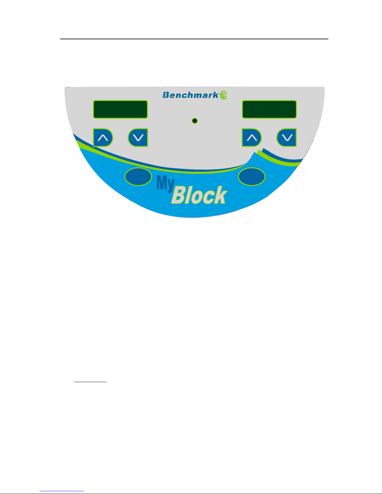
2. Keypads
Temp.
Temp.
℃
℃
External
External
TM
TM
Time
Time
StopStart
StopStart
3. Display
Mode
Start
Stop
The “Mode” button is used to toggle between the time
and temperature setting.
Down key: Used in both time and temperature mode to
decrease the settin
Up key: Used in both the time and temperature mode to
increase the setting.
Start/Stop key. After the temperature and time setting is selected,
press this key to start the timer. This key can also be pressed to
stop the timer.
.
— 4 —

BSH5000 Operation manual Chapter 4 Operation Guide
Chapter 4 Operation
1. Temperature and time setting
a) Press the On/Off switch to power on the
instrument. The instrument performs a self
test followed by an alarm to signal that the
product is ready for use.
b) After about 3 sec. the temperature will
automatically increase to the most recent
setting. The values shown on the display
are actual settings (real time temperature &
time remaining.) The example shows an
actual temp. of 28.5°C and 35 min. remaining.
c) To adjust the set temperature,use the and
keys to selectl the desired temperature (Ex.
55.5). After 5 seconds, the temperature is
stored and the instrumnent will begin heating.
d) To set the time, Press the “Mode” key, the
displayed time begins flashing, press or
keys to set the desired time (ex. 1 hr 20 min.).
After 5 seconds the desired time is stored.
NOTE: The timer will not begin unless the
“Start/Stop” button has been pressed
— 5 —

BSH5000 Operation manual Chapter 4 Operation Guide
2.
Timer Operation (Advanced)
The default setting of the instrument is designed so that the heater will continue to hold
the set temperature even once time has expired and “oVEr” is showing on the time display.
This setting can be adjusted so that the heater will shut down once time has expired. To
adjust the advanced timer setting pres the “Mode” key and hold it for 10 seconds. After
10 seconds, the display will show “OP:1” use the or key to select “OP:2”. The
setting has now been changed and can be stored by pressing the “Start/Stop” key.
3. Temperature Calibration
The temperature of the instrument has been calibrated prior to shipment from the
factory. However, in the event that an adjustemnt to the calibration is required, the
user can adjust the calibration with either a thermometer/thermocouple or with the
optional external temperature probe. (sold separately).
Caution: the instrument uses double temperatures adjustment to ensure accuracy over
a wide range of temperature. It is linearly adjusted at both 40° and 100°C.
a) Calibration with a thermometer:
— 6 —
BSH5000 Operation manual Chapter 4 Operation Guide
a) Power on the machine and ensure that the temperature on the display is less than
35°C.
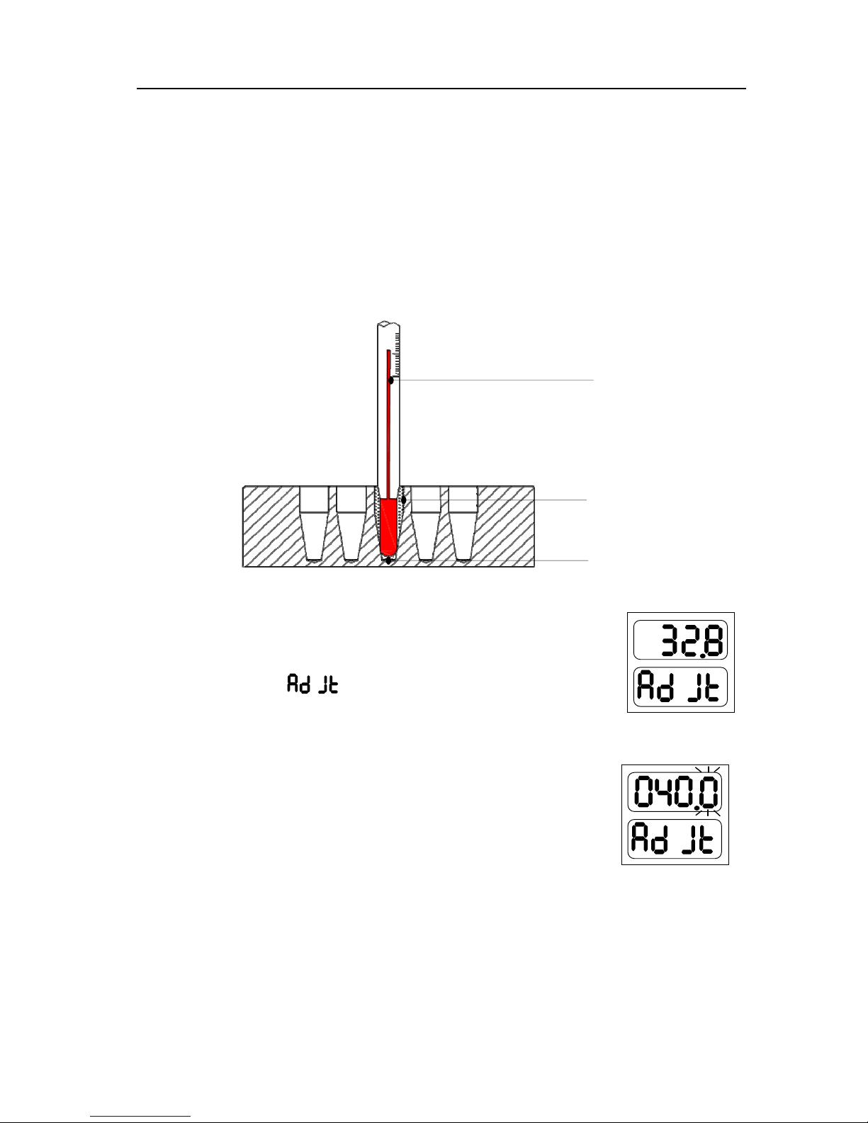
b) Inject olefin oil into one of the cone-shaped wells, and then put a
thermometer/thermocouple into this well (make sure that the precision of the
thermometer should be within 0.1℃ and the temperature ball should be absolutely
immerged into the cone-shaped well). See Fig a.
Thermom
Fig a
c) Press “Mode” key without releasing, then press key
at the same time and hold for 3 seconds, it will enter into
the temperature calibration interface, see the right.
At this point, “ ” displayed, which indicates entering
into temperature calibration program. The temperature
displayed is current temperature and begins to rise to
40.0° automatically.
When the temperature reaches to 40° and is able to hold
a constant temperature, the decimal digit begins to flicker.
After 20 minutes, the user can read the value on the
Thermometer and use the up and down keys to enter the
value of the thermometer.
Notes: Please read the actual value after 20 minutes’ constant
Olefin
cone-shape
— 7 —

BSH5000 Operation manual Chapter 4 Operation Guide
temperature to ensure the calibration accuracy.
If the actual read out of thermometer is 39.6, modify the
temperature to 39.6 by pressing or . Then press “Start/Stop”
to confirm the input value.
d) Then the instruments will the automatically begin to heat to 100℃. Once 100C is
reched and held as constact, the decimal begins to flicker. After 20 minutes, the
user can read the actual value from thermometer.
Notes: Please read the actual value after 20 minutes’ constant temperature to ensure
the calibration accuracy.
If the actual readout is 101.5, modify the temperature display
to 101.5 by pressing or . Then press “Start/Stop” to confirm
the input value.
Note: Pressing “Set” and “” simultaneously during the temperature calibration
indicates exiting the temperature calibration program. The adjustments will be
cancelled and the changed value will be of no effect.
3.2. Calibration with the External sensor:
a) Power on the machine and ensure that the temperature on the display is less than
35°C.
b) Put External sensor into a block well.
c) Press “Mode” key without releasing, press “Start/Stop” key
and hold for 3 seconds, it will enter into temperature
calibration interface, see the right. At this point, “ ”
displayed, which indicates entering into external temperature
calibration program. The temperature displayed is External
sensor’s current temperature and it begins to rise to 40.0°
automatically.
It will automatically display “ ” six seconds later.
— 8 —

BSH5000 Operation manual Chapter 4 Operation Guide
The upper displayed temperature (Ex. 32.0) is the
current temperature measured by the External sensor.
When the temperature reaches to 40° and is held as constant
the decimal digit begins to flash.
Notes: Please allow 20 minutes before reading the
displayed actual value to ensure the calibration accuracy.
Press “Mode” key to view the temperature value of External
Sensor. If the displayed value is 39.6°C.
Press “Mode” again, or wait for 6 seconds, then display
“
” , modify the displayed temperature to 39.6 by
pressing or . Then press to confirm the input value.
d) Then the instrument will heat to 100℃ automatically. Once 100 ℃ has been
reached and held constant, the decimal point will begin to flash.
Notes: Once flashing, the user must allow 20 minutes before proceeding to the next
step. This will ensure calibration accuracy.
Press the “Mode” key to show the actual readout of
The external sensor (for ex. 101.5℃).
Press “Mode” again, or wait for 6 seconds, then display
“
” , modify the displayed temperature to 101.5 by
pressing or . Then press to confirm the input value.
Note: Pressing “Mode” and “Start/Stop” simultaneously during the temperature
calibration indicates exiting the temperature calibration program. The
— 9 —

BSH5000 Operation manual Chapter 4 Operation Guide
procedure will be cancelled and the changed value will have of no effect.
4.Temperature control by external sensor
a) Insert the external temperature probe into a well of the drybath or directly into a
sample tube.
b) Press and hold “Stop”, then simultaneously press and hold “” for 3 seconds, the
external indicator light goes on to indicate that it has entered into the temperature
control mode of external sensor.
Note: After entering into the external temperature control mode, the user can
simultaneously press “Stop” and "" for 3 seconds to exit this mode. Upon
exiting the external indicator light will go off.
— 10 —

BSH5000 Operation manual Chapter 5 Failure Analysis and Troubleshooting
Chapter 5 Failure Analysis and Troubleshooting
Problems and actions
No. Common problem Possible cause Action(s)
No display on the
1
screen
The actual and
2
displayed temperatures
are quite different
“OPEn” displayed,
alarming “beep”
“SHOr” displayed,
3
alarming “beep”
No power on the main
power plug
Faulty fuse Change fuse
On/Off button broken Change button
Others Contact the supplier
Broken sensor or
loose contact of the
block
Sensor disconnect
Sensor short-circuit
Check power supply and
plugged properly
Contact the supplier
Contact the supplier
“HHHH” displayed,
alarming “beep”
4 No heating
5 Keys don’t work Faulty key Contact the supplier
Sensor broken, or
block temperature is
too high
Sensor broken
Contact the supplier
Heating tube broken
— 11 —

BSH5000 Operation manual Annex
Annex:Wiring Diagram
(
for reference only)
L
PE
N
Switch
POWER
J1 AC 220 V
BOARD
J4 Heat
J2 AC9V
J3 HeatCtl
HEAT
Block
PT100
J1 AC9V
MAIN
BOARD
X1 He atCtl
J2 PT100 J4 PT1000USB1 USB
J3 J2
CONN BOARD
USB PT1000
— 12 —

Memo
 Loading...