


PDX3000

i
Serial & USB Interface Customer Displays
2 by 20 character display
USER MANUAL
Oct 2018
PDX3 / LDX9 / LTX9 / LDX1 Series

ii
NOTICE
The manufacturer of the POS pole display makes no representations or warranties,
either expressed or implied, by or with respect to anything in this manual, and shall
not be liable for any implied warranties of fitness for a particular purpose or for any
indirect, special or consequential damages. Information in this document is subject to
change without notice and does not represent a commitment on the part of the
manufacturer.
FCC NOTICE
This equipment generates, uses, and can radiate radio frequency energy and if not
installed and used in accordance with this manual, may cause interference to radio
communications. It has been tested and found to comply with the limits for a Class A
digital device pursuant to Subpart J of Part 15 of FCC Rules, which are designed to
provide reasonable protection against interference when operated in a commercial
environment. Operation of this equipment in a residential area is likely to cause
interference in which case the user at his own expense will be required to take
whatever measures may be required to correct the interference.
LOGIC CONTROLS, INC.
A Bematech Company
999 S. Oyster Bay Road
Building #104
Bethpage, NY11714
TEL: (516) 248 0400
FAX: (516) 495 4075
www.bematechus.com

iii
Table of Contents
1 FEATURES ......................................................................................................... 1
2 CARTON CONTENTS ......................................................................................... 2
3 HARDWARE INSTALLATION ............................................................................. 3
3.1 STEPS FOR HARDWARE INSTALLATION .......................................................................3
3.1.1 Serial interface displays ........................................................................................................... 3
3.1.2 USB interface displays ............................................................................................................. 3
3.2 INTERFACE SPECIFICATION .........................................................................................4
4 USB DRIVER INSTALLATION ............................................................................ 6
4.1 WINDOWS XP, WINDOWS 7 AND WINDOWS 8 ..................................................6
4.2 MAC OS X 10.6.6, 10.6.6 X64, 10.5.8 INTEL, 10.5.8 PPC .......................................9
4.3 LINUX KERNEL 2.6.XX ........................................................................................10
5 COMMAND SETS AND CONFIGURATION ...................................................... 12
5.1 DOWNLOAD COMMAND SETS ..........................................................................12
5.2 SERIAL PORT CONFIGURATION .................................................................................15
5.3 SELECT COMMAND SET .....................................................................................16
6 FUNCTIONAL TEST .......................................................................................... 17
6.1 COM (VIRTUAL) PORT INTERFACE ............................................................................17
6.2 DEVICE NAME INTERFACE ........................................................................................17
7 OPOS DRIVER INSTALLATION ....................................................................... 18
8 COMMAND SETS DESCRIPTION ................................ ................................ .... 19
8.1 LCI GROUP COMMAND SETS ....................................................................................19
8.1.1 Logic Controls (LCI) Command Set ...................................................................................... 19
8.1.2 Aedex Command Set............................................................................................................... 23
8.1.3 Noritake Command Set .......................................................................................................... 24
8.1.4 LCI3400 Command Set .......................................................................................................... 26
8.1.5 UTC1100(SD) Command Set ................................................................................................. 28
8.1.6 UTC1100(EN) Command Set ................................................................................................. 30
8.1.7 UTC220XLT Command Set .................................................................................................... 32
8.1.8 Epson110-D202 Command Set .............................................................................................. 34
8.2 EMAX COMMAND SET ...............................................................................................37
8.3 FIRICH COMMAND SET ..............................................................................................38
8.4 IEE COMMAND SET ..................................................................................................42
8.5 PTC7220 COMMAND SET .........................................................................................45
9 CHARACTER CODE TABLES .......................................................................... 49
10 GENERAL SPECIFICATIONS ........................................................................... 58

1
1 FEATURES
The PDX3000/LDX9000/LTX9000/LDX1000 family of universal command customer
displays offers a wide range of high quality features and models to choice from. Listed below
are the features incorporated into each customer display. Not all features are available in all
models. The model identification chart will assist you in selecting the model best suited to the
application needs.
The PDX3000/LDX9000/LTX9000/LDX1000 family line displays of serial port or USB port
interfaces has been pre-assembled to make the installation as simple as possible.
Two line display with twenty 5/9 mm high characters each line
Bright blue-green fluorescent display
Available as pole displays (PDX3000/LDX9000/LDX1000) and table-top displays
(LTX9000)
Pre-downloadable or Pre-selectable command sets for emulating current and future
customer displays
Supports wide variety of languages with multiple fonts, including English, Spanish,
German, French, and Italian, …
Programmable power-up default setting for international symbols and font code
selection
OPOS/JPOS compatible
Better visibility due to optically matched anti-scratch lens and wider character pitch
Long life and trouble free operation
Adjustable viewing angles
Available with 120VAC / 220VAC power adapters
Available in beige or dark gray
Port powered or self-powered USB interface
Direct RS232C, or RS232 pass-thru interface
Programmable RS232C baud rate, supporting high speed up to 19,200 baud rate
User definable character
Automatic standard or smart message scrolling on top or bottom line
Real time clock display
One time message scrolling

2
2 CARTON CONTENTS
PDX3000
LDX9000
LTX9000
LDX1000
1
PDX3 pole display
LDX9 pole display
LTX9 table display
LDX1 pole display
2
USB/DB9 cable with MiniDIN10
interconnector detachable from main cable
USB/DB9 cable,
detachable
USB/DB9 cable 3 Power adapter 7.5VAC/DC
Power adapter 5VDC
4
Metal base plate with mounting hardware
N/A
Metal base plate with
mounting hardware
5
Quick Installation Guide

3
3 HARDWARE INSTALLATION
The PDX3000/LDX9000/LTX9000/LDX1000 family of universal line displays has been preassembled to make the installation as simple as possible. Please follow steps below for
models of different interfaces.
3.1 Steps For Hardware Installation
3.1.1 Serial interface displays
Mount the pole display to the metal base plate using the mounting hardware provided.
The pole display can be used in a freestanding mode or attached to the counter using
the remaining mounting hardware.
Connect the DB9F connector to the computer’s serial port (for example, COM1 or
COM2) if serial interface model is used.
For serial pass-through model, connect the DB25M connector to the peripheral device
and turn on power of the peripheral device.
Connect the female power jack of the power adapter to the male power jack of the
interface cable.
Plug the power adapter into a 120VAC outlet.
A start up text message will be present for a short time to identify the selected
command set and selected baud rate. When this message disappears the cursor will be
displayed at the left-most digit of the top row.
3.1.2 USB interface displays
Mount the pole display to the metal base plate using the mounting hardware provided.
The pole display can be used in a freestanding mode or attached to the counter using
the remaining mounting hardware.
Install USB driver following instructions on "USB DRIVER INSTALLATION"
section.
Plug the USB cable from the pole display into the computer’s USB port.
For double sided USB pole displays, connect the female power jack of the power
adapter to the male power jack of the interface cable and plug the power adapter into a
120VAC outlet.
A start up text message will be present for a short time to identify the selected
command set. The test message will NOT be present until USB driver is installed
correctly. When this message disappears, the cursor will be displayed at the left-most
digit of the top row.

4
3.2 Interface Specification
There are several connection interfaces for the PDX3000/LDX9000/LTX9000/LDX1000
family of universal displays.
USB Interface Connector
All USB pole displays will have standard USB type-A connectors. It is connected to
the USB port of the computer.
1: V+
2: D3: D+
4: Ground
Serial Interface Connector
The pin out configuration for the standard serial pole display is a DB9F connector. It
plugs directly into the serial port of the computer.
1: DCD (tied to pins 4&6)
2: NC
3: TXD from PC
4: DTR (tied to pins 1&6)
5: Ground
6: DSR (tied to pins 1&4)
7: RTS (tied to pin 8)
8: CTS (tied to pin 7)
9: +5 VDC
Serial pass-through Interface Connectors (LDX9000 & PDX3000 only)
For pass-through models, the display cable comes with two connectors. The DB9F is to be
connected to the computer while the DB25M is for connection to the peripheral.
To computer:
1: DCD (tied to pins 4&6)
2: TXD to PC
3: RXD from PC
4: DTR (tied to pins 1&6)
5: Ground
6: DSR (tied to pins 1&4)
7: RTS (tied to pin 8)
8: CTS (tied to pin 7)
9: +5 VDC
DB9F (to computer)
DB9F (to computer)

5
To peripheral:
1: NC
2: TXD to peripheral
3: RXD from peripheral
4: RTS
5: CTS (tied to pin 20)
6: NC
7: Ground
8: NC
9-19: NC
20: DTR (tied to pin 5)
21-25: NC
DB25M (to peripheral)
6
4 USB DRIVER INSTALLATION
4.1 WINDOWS 7 and WINDOWS 8 and WINDOWS 10
The USB drivers are available on our web site at www.logiccontrols.com. Please download
and unzip the driver files before installation. There are two types of driver interface available.
If the POS software is only able to access COM port for the pole display, use the virtual
COM port interface. After the driver is installed, the USB interface will be assigned a COM
port name so that the POS software will be able to communicate with the USB display as a
COM port. Note that the operating system will assign the display a different COM port
number if the display is plugged into a different USB port. Another driver interface use a
specific device name (\\.\LCPD3\, \\.\LCLD9\, or \\.\LCLD1\) to access the pole display
directly.
Install this driver if you are using OPOS or the POS software was tailored to use this device
name.
1. DO NOT plug the device in USB port
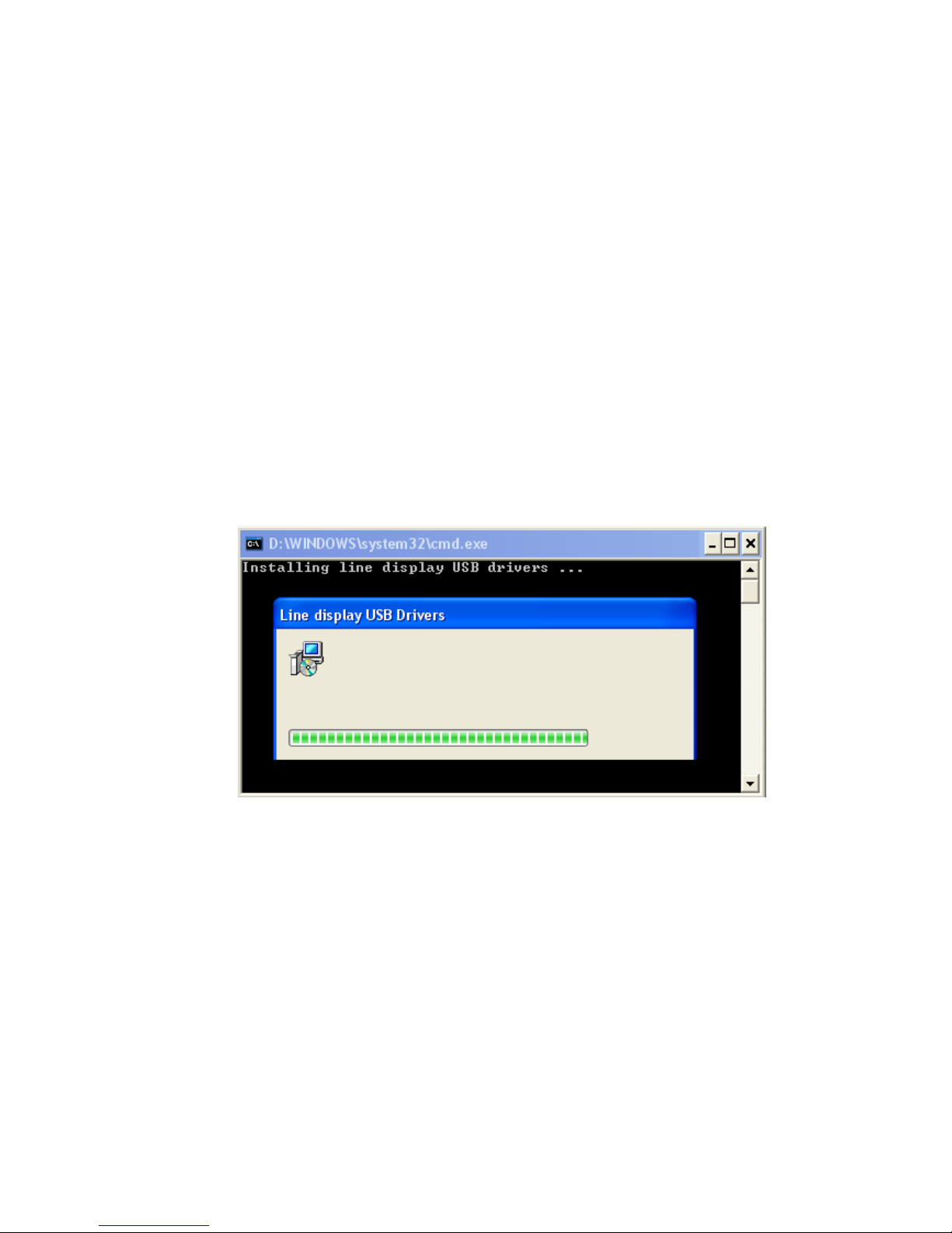
2. Run “install.bat” batch program in this driver package:
3. Plug the device in USB port and wait for the hardware wizard message box to
display:

7
4. Click <Next> button to continue installation automatically. When finished, click
<Finish> button to end installation (this can delay some seconds):
5. Invoke Device Manager to check COM port number or the device driver's
name. The driver is installed under "Ports (COM & LPT)":
8
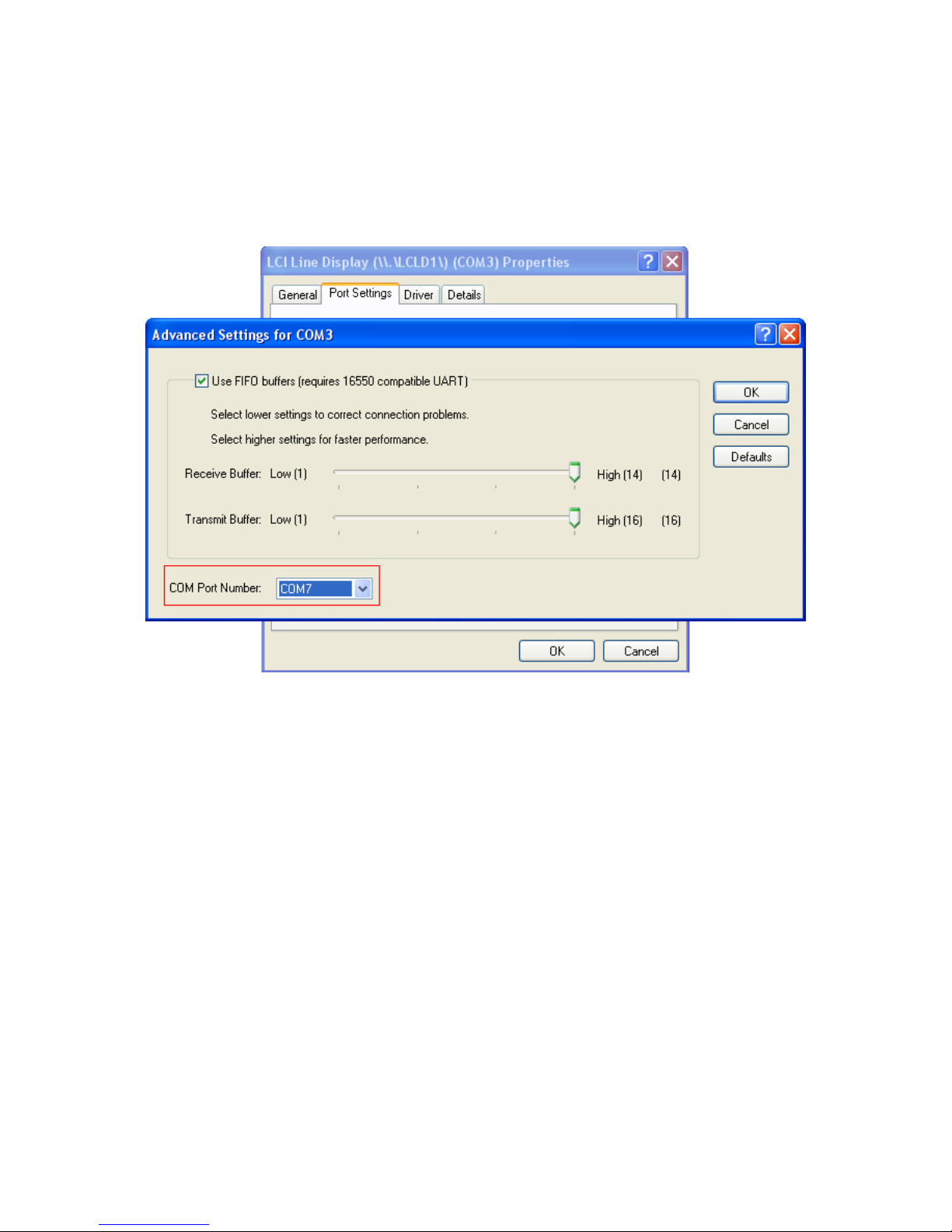
6. To change the assigned COM port number, double click "LCI Line Display
(\\.\LCLD9\) (COMx)" to display the Properties dialog box and select <Port
Settings> tab. Then click <Advanced...> button
7. Click on COM port number box to select from the list of unused port number
and click <OK> to accept new settings (example COM7):
8. Unplug the device and plug the device again to check COM7.
NOTE:
It’s better to set the virtusl COM port number x between 1 – 8.

9
4.2 MAC OS X 10.6.6, 10.6.6 X64, 10.5.8 INTEL, 10.5.8 PPC
Latest USB drivers are available on our web site at www.bematechus.com.
Please download and unzip the driver files before installation.
1. DO NOT plug the line display in USB port
2. Download the zip file into “Documents” folder. Unzip the zip file.
3. Double-click “Install_lcpdDll” to Install LCI pole display API library.
4. Plug the pole display to Mac PC USB socket. And wait until a logo message
displayed on the screen of the device.
5. Run the testing program by double clicking “QcPdUsb” to test the API.
Note1:
If error message box pop out:
1. "QcPdUsb cannot be opened because of a problem" - the driver was not
installed properly.
2. "No LCPD devices found" - check the connection of the USB line display with
Mac PC.
3. "... tty ..." - do the followings:
Open the terminal in the “Applications -> Utilities”.
Run “cd usr”.
Run “cd local”.
Run “sudo rmdir lib” to remove the folder.
Run “cd ..” to return to "usr" folder.
Run “sudo rmdir local” to remove the folder.
Run “cd ..” to return to current user folder.
Run “sudo rmdir usr” to remove the folder.
Note2:
To run the testing program in a terminal:
1. Open a terminal window.
2. Navigate to the testing program folder with “cd” command.
3. Run “chmod 755 example” in the terminal window.
4. Run “./example”.

10
4.3 LINUX KERNEL 2.6.XX
1. Login as root user.
2. Copy "setup" folder to Linux.
3. Modify the permissions of "install.sh" and "testlcpd" by the following
command:
chmod 777 install.sh
chmod 777 testlcpd
4. Modify install.sh according to your Linux distribution.
Type "vi install.sh"
Find the line of "AUTO_FILE=/etc/rc.d/rc.local",
If you use Redhat/Fedora, keep it as it's.
If you use Suse, modify it to "AUTO_FILE=/etc/rc.d/boot.local"
If you use Ubuntu/Xubuntu, modify it to "AUTO_FILE=/etc/rc.local"
5. Install driver:
Type "./install.sh".
6. Enter the auto-run shell script as step 4, add the following line right
after "mknod /dev/usb/lcpd c 180 128" line.
chmod 777 /dev/usb/lcpd
7. In the script as step 4 (for example, rc.local or boot.local), if "exit 0"
line exists, please move it to the LAST line!
8. Type "lsmod" to check if "usblcpd" has been loaded into system.
lsmod | grep usblcpd
9. Connect PD to USB Port.
10. Test PD.
After installed driver, enter "setup" folder and type "./testlcpd" to
see if data on PD.
11. If you want to change USB port in which PD's plugged, please
follow the steps below.
Unplug the USB cable of PD.
Run "rmmod usblcpd" and "rm /dev/usb/lcpd" commands.
Replug in USB cable of PD to another USB port.
Run "./install.sh" again under setup folder.

11
Note:
Tested under Fedora 5 (Kernel:2.6.15-1.2054_FC5smp), Suse 10
(2.6.16.60-0.21-smp), and Xubuntu 8.10 (Kernel:2.6.27-7-generic)
PRE-REQUERIMENTS:
Linux Kernel source files installed on the system
Ex:
for debian/ubuntu, type
"sudo apt-get install linux-source¨.
To development tools installed (gcc).
12
5 COMMAND SETS AND CONFIGURATION
5.1 DOWNLOAD COMMAND SETS
The PDX3000/LDX9000/LDX1000 family of pole displays is controlled by command codes
and data from the computer. The pole display is able to emulate different popular command
sets to meet requirements of different POS software. Please download the required command
set to the display according to requirement of the POS software with the provided download
utility software.
The tool for download and the files containing the set of commands are available on our web
site at www.logiccontrols.com. Please download and unzip the files before installation.
See the description of the set of commands in < COMMAND SETS DESCRIPTION> section
to select one command set in “Select One of Command Sets” box for downloading:
EMAX – Emax command emulation
FIRICH = Firich command emulation
IEE – Iee command emulation
LCIGP – Logic Controls command set group
PTC – PartnerTech CD7220/5220 command emulation
The utility program must be in the same folder as all command files.
1. If the pole display is connected in USB socket, disconnect and connect again in USB
socket. Don't send any command to pole display until to transfer the new set
command.
2. Run the software utility existent in the package.
Or, a USB device name interface selected in <Port Name>.

13
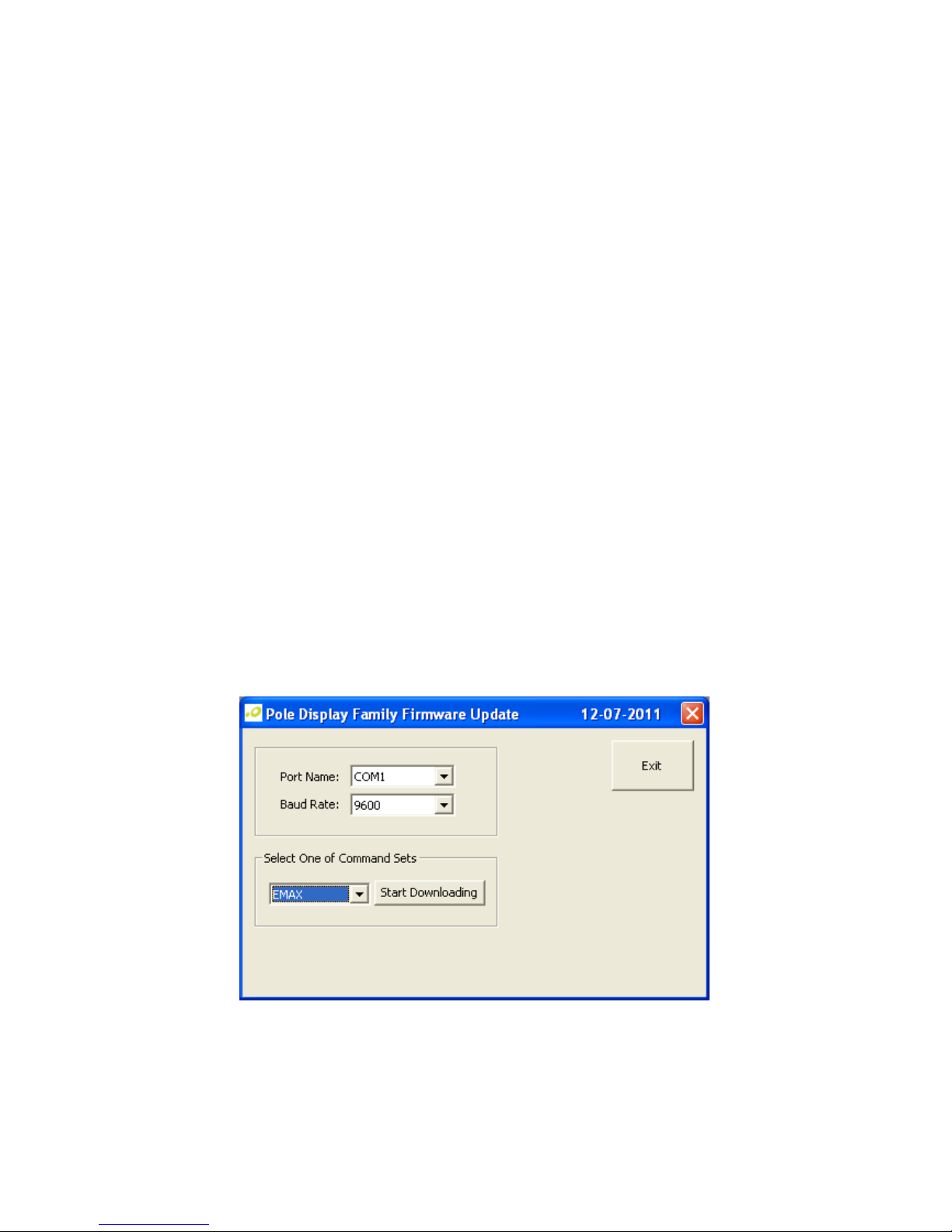
3. Select the <Port Name>, and baud rate if USB device name interface is NOT selected.
Select the set command and click <Start Downloading> button (example below for
Emax set commands):
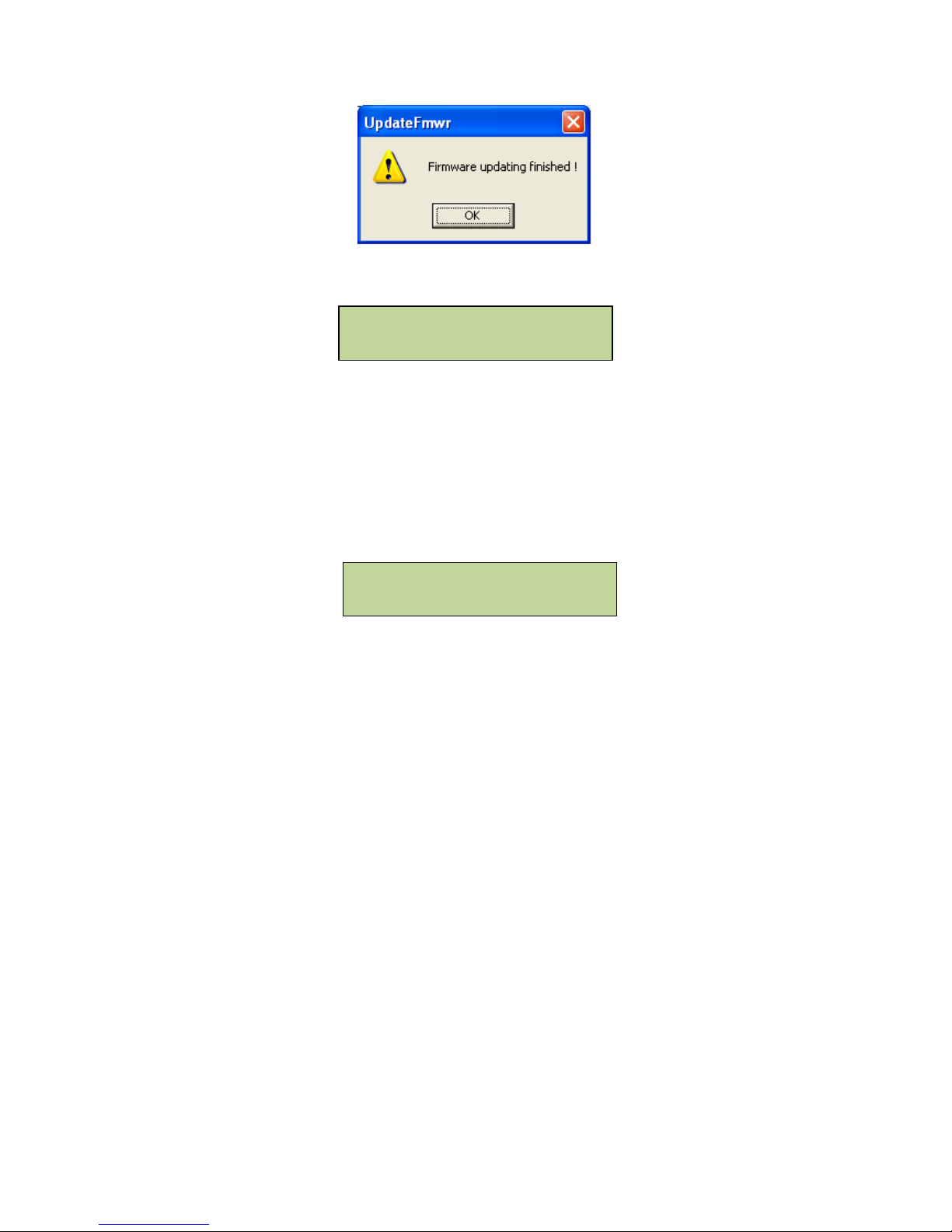
4. The pole display will show:
5. Wait for the final message (below success):
LOGIC CONTROLS
DOWNLOADING CODE
14
The pole display will show:
xxxxx = Name of command set.
Example: <LCI> for Logic Controls
Vyy.yy = Firmware version of the pole display.
zzzzz = Serial port baud rate if NOT USB interface
NOTE:
If the pole display shows:
The command set downloading is NOT successful. Do the steps 1 – 5 again. The baud rate
must be 9600 if a serial interface used.
xxxxx Vyy.yy
zzzzz
DOWNLOADING FAILURE
Boot Vyy.yy

15
5.2 Serial Port Configuration
The pole displays with serial interface were factory configured for serial RS232C
interface using the following protocol:
· Baud Rate: 9600
· Data Bits: 8
· Stop Bit: 1
· Parity: None
The baud rate is programmable with the software utility.
Configuration options are as follows:
2400
4800
9800
19200
1. Select the port name and the baud rate in the “Communication Port” group
box. The baud rate must match the baud rate data shown on the pole display.
2. Select the baud rate in the “Configure Port” group box.
3. Click “Save to Pine Display” to save the configuration into the display.
Then the pole display will be reset automatically, and show the new baud rate saved.

16
5.3 SELECT COMMAND SET
A software utility can be used to select one of the command sets when LCIGP is
downloaded in flash ROM. This is default firmware downloaded in the pole display.
Run the software utility.
Command set options are as follows:
LCI – Logic Controls command set with OPOS command codes
AEDEX – Aedex command emulation
NORITAKE – Noritake command emulation
LCI3400 – Logic Controls PD3400 model command emulation
UTC1100(SD) – Ultimate1100 command emulation with initial stand mode
UTC1100(EN) – Ultimate1100 command emulation with initial enhanced mode
UTC220XLT – Ultimate220XLT command emulation
EPSON110-D202 – Epson 110-D202 command emulation
1. Select the port name and the baud rate in the “Communication Port” group
box. The baud rate must match the baud rate data shown on the pole display.
2. Select the command set.
3. Click “Save to Pole Display” to save the command into the display.
Then the pole display will be reset automatically, and show the new command set
saved.
 Loading...