

Page 1
Page 2

KC-4112 Service´s Manual
P/N: 6705 . Rev.1.0
December 2005
(First edition)
Copyright by Bematech S.A. Curitiba, Brazil.
All rights reserved.
No part of this publication may be copied, reproduced, adapted or translated without the prior written
permission of Bematech S.A., except when allowed by patent rights.
Information in this publication is purely informative, subjected to change without notice and no liability is assumed
with respect to the use of this. However, as product improvements become available, Bematech S.A. will make
every effort to provide updated information for the products described in this publication. The latest version of this
manual can be obtained through Bematech website:
www.bematech.com
Notwithstanding the other exceptions contained in this Manual, the consequences and responsibility are
assumed by the Purchaser of this product or third parties as a result of: (a) intentional use for any improper,
unintended or unauthorized applications of this product, including any particular purpose; (b) unauthorized
modifications, repairs, or alterations to this product; (c) use of the product without complying with Bematech
S.A. Corporation’s operating and maintenance instructions; (d) use of the product as component in systems or
other applications in which the failure of this could create a situation where personal injury or material
damages may occur. In the events described above, Bematech S.A. and its officers, administrators, employees,
subsidiaries, affiliates and dealers shall not be held responsible or respond by any claim, costs, damages,
losses, expenses and any other direct or indirect injury, as well as claims which alleges that Bematech S.A.
was negligent regarding the design or manufacture of the product.
Bematech S.A. shall not be liable against any damages or problems arising from the use of any options or any
consumable products other than those designated as original Bematech products or approved products by
Bematech S.A.
Any product names or its logotypes mentioned in this publication may be trademarks of its respective owners
and shall be here recognized.
Product warranties are only the ones expressly mentioned in the User’s Manual. Bematech S.A. disclaims any
and all implied warranties for the product, including but not limited to implied warranties of merchantability or
fitness for a particular purpose. In addition, Bematech S.A. shall not be responsible or liable for any special,
incidental or consequential damages or lost profits or savings arising from the use of the product by the
Purchaser, the User or third parties.
2
Page 3

EMC and Safety Standards Applied
Product Name: KC-4112
Model Name: 6200 and 6300 (all)
*EMC is tested using an EPSON PS180 power supply
Europe:
CE marking
Safety: EN60950
North America:
EMI: FCC Class A
Safety: UL recognized
WARNING
The use of non-shielded communication cables as well as unauthorized changes or modifications on the
equipment could void the certifications described in this page. Please contact your dealer for further information.
CE Marking
The printer conforms to the following Directives and Norms:
Directive 89/336/EEC
EN 55022 Class B (Conducted and Radiated emission)
EN 55024
IEC 61000-4-2 ESD
IEC 61000-4-3 Radiated immunity
IEC 61000-4-4 EFTB
IEC 61000-4-5 Surge
IEC 61000-4-6 Conducted immunity
IEC 61000-4-11 Voltage Dips
FCC CLASS A
DECLARATION OF CONFORMITY
This equipment has been tested and found to comply with the limits for a Class A digital service, pursuant to Part
15 of the FCC Rules. These limits are designed to provide reasonable protection against harmful interference when
the equipment is operated in a commercial environment. This equipment generates, use and can radiate radio
frequency energy and, if not installed and used in accordance with the instruction manual, may cause harmful
interference to the radio communications. Operation of this equipment in a residential area is likely to cause
harmful interference in which case the user will be required to correct the interference at his own expense.
3
Page 4

Safety Precautions
This section presents important information intended to ensure safe and effective use of this product. Please
read this section carefully and store it in an accessible location.
Immediately unplug the equipment if it produces smoke, a strange odor, unusual noise or if foreign matter
including water or other liquid falls into the equipment. Continued use may damage it or lead to fire *. Please
contact your dealer or a BEMATECH service center for advice.
Never attempt to repair this product yourself. Improper repair work can be dangerous.
Never disassemble or modify this product. Tampering with this product may result in injury or fire *.
Be sure to use the specified power source. Connection to an improper power source may cause malfunction or
fire *.
CAUTION:
WARNING:
Do not connect cables in ways other than those mentioned in this manual. Different connections may cause
equipment damage and burning *.
Be sure to set this equipment on a firm, stable surface. The product may break or cause injury if it falls.
Do not install this equipment in locations that do not comply with the environmental requirements specified in
this manual.
Do not place heavy objects on top of this product. Never stand or lean on this product. Equipment may fall or
collapse, causing breakage and possible injury.
To ensure safety, unplug this product before leaving it unused for an extended period. In this case, please be sure
to place a piece of paper between the platen and the paper roll, in the thermal mechanism, to avoid damage
when restarting the printer.
* Note that this equipment was developed complying with international safety standards and therefore contains
only limited flammability components.
NOTICE:
If static electricity or electromagnetism causes data transfer to discontinue midway (fail), restart the application
or disconnect and connect the communication cable (USB, etc…) again.
4
Page 5

SummarSummar
Summar
SummarSummar
Chapter 1 - Introduction ................................................................................ 6
Chapter 2 - Getting Started ............................................................................. 7
Chapter 3 - Product Information .................................................................... 9
Chapter 4 - Communication Interfaces ............................................................. 13
Chapter 5 - Technical Specifications ................................................................. 16
Chapter 6 - Dip Switch .................................................................................. 17
Chapter 7 - General Flowchart ........................................................................ 18
Chapter 8 - Blocks Diagram ........................................................................... 20
Chapter 9 - Testing ........................................................................................ 21
Chapter 10 - Troubleshooting ......................................................................... 23
Chapter 11 - Replacing Deffective Parts or Modules ........................................... 27
Chapter 12 - Preventive Maintenance ............................................................... 36
yy
y
yy
Appendix A - Family Codes ............................................................................. 38
Appendix B - Field Replacement Unit (FRU´s) ................................................... 40
Appendix C - Firmware Update ........................................................................ 42
Appendix D - Assemblies ................................................................................ 45
5
Page 6

Chapter 1
IntroductionIntroduction
Introduction
IntroductionIntroduction
How this manual is organized:
• Chapter 2 and 3 refers to product presentation (unpacking, packing, product components, operations and
handling).
• Chapters 4 refers to interfaces and communications.
• Chapters 5 to 8 refers to the technical information of the product. It contains a flowchart, a block diagram
that compose the kiosk printer and its accessories besides the technical specifications.
• Chapters 9 to 12 refers to tests that may be run in order to help diagnosing a faulty product. It shows how
to indentify and replace a deffective part or module and how to avoid future problems.
• Appendix A lists the available product configurations and corresponding part numbers.
• Appendix B lists the Fild Replacement Unit (FRU´s) that may be used to repare the product.
• Appendix C explains the firmware update procedure.
• Appendix D shows all optional assemblies configuration
6
Page 7
Chapter 2
Getting StartedGetting Started
Getting Started
Getting StartedGetting Started
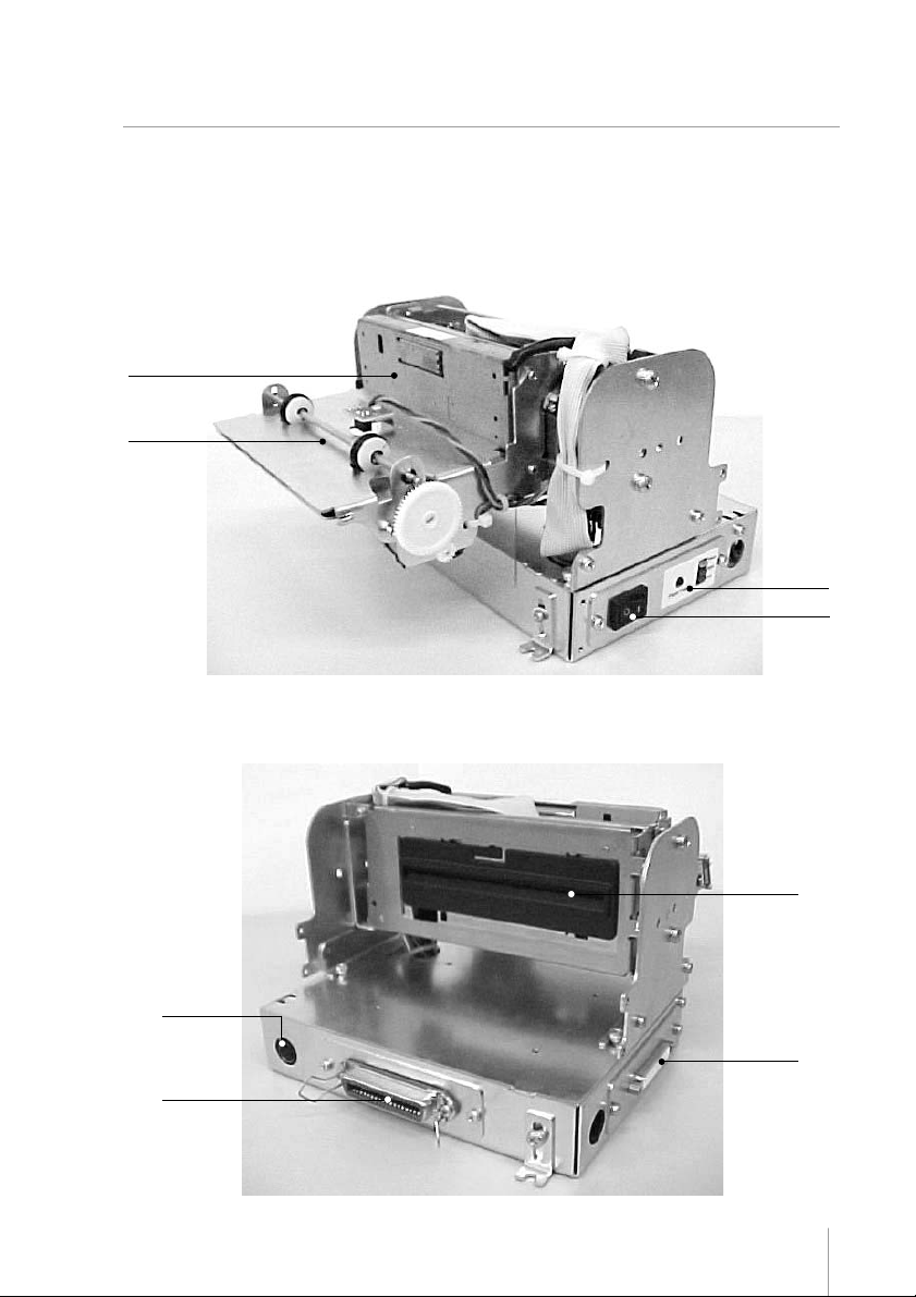
The printer
The communication connectors, DC connector, On/Off switch and key panel can be found in different locations of
the printer, according to the selected assembly.
Cutter
Presenter
Key panel
On/Off switch
Figure 1
DC connector
Parallel
connector
Figure 2
Paper
entrance
Serial
connector
7
Page 8
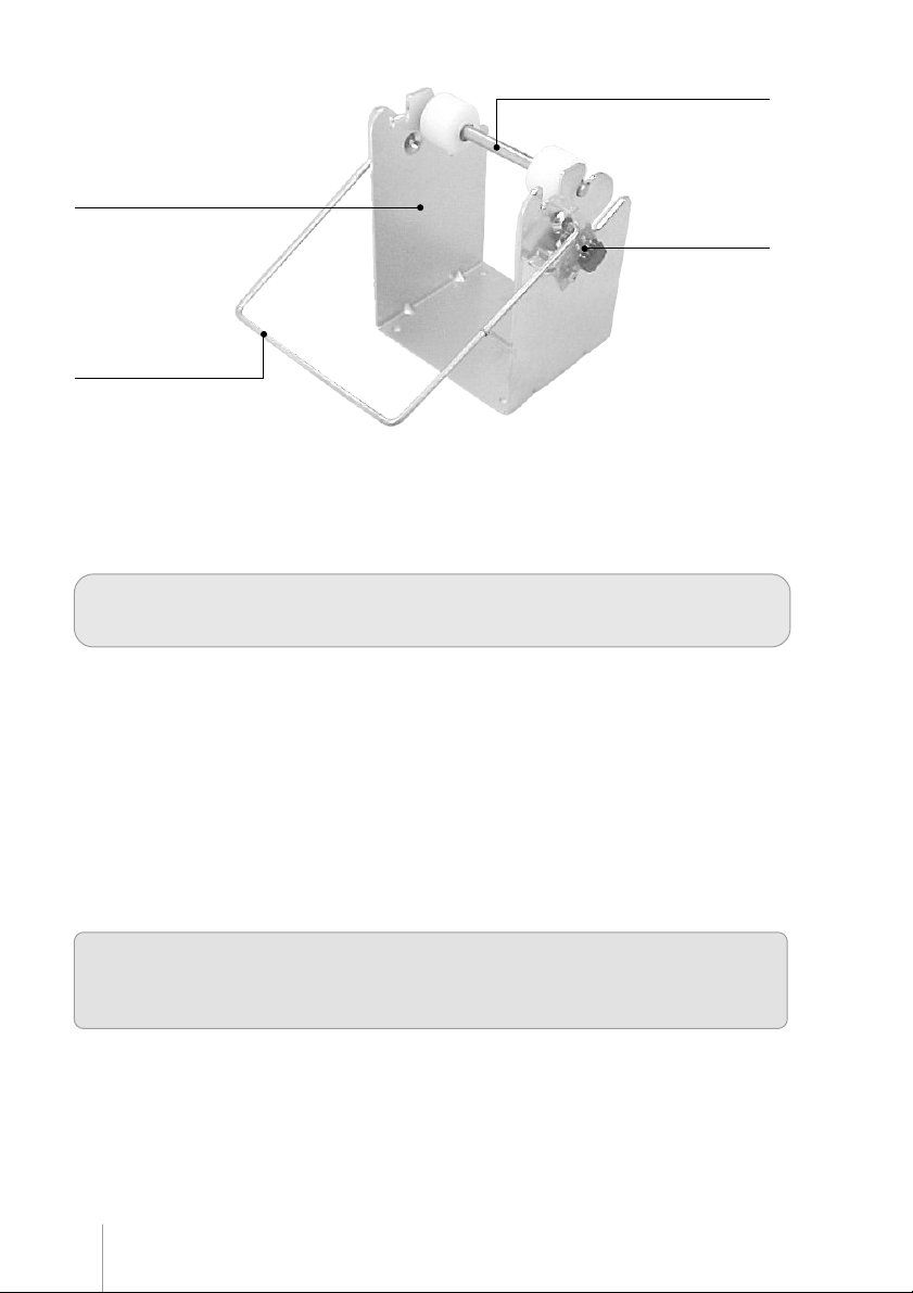
Paper holder
Paper near end sensor
Damping device
Figure 3
Paper roll is not included – the appropriate thermal paper should be used. Refer to the Technical
Specifications section in this manual for paper details.
Spindle
Unpacking
Take the printer out of its box and verify that the following items are included:
• Printer
• User´s Manual
Keep the box and packing materials for future use if necessary.
Paper roll is not included – the appropriate thermal paper should be used. Refer to the Technical
Specifications section in this manual for paper details.
Be sure to follow current laws or regulations before disposing parts or packing materials
8
Page 9
Chapter 3
Product InformationProduct Information
Product Information
Product InformationProduct Information
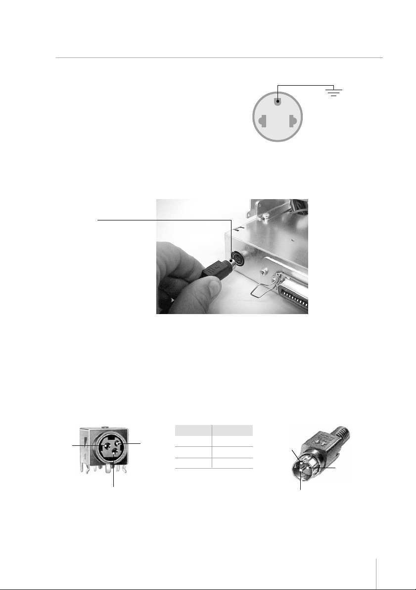
Powering
Make sure that the printer is turned off.
Connect the power cord to the power supply‘s
AC connector and to an electrical outlet. This
outlet must have its ground pin connected as
shown on the right:
Figure 4
Connect the DC cable of the power supply in the printer as shown below – note that the arrow in the connector must
be facing up:
DC
connector
Figure 5
GROUND
Turn on the printer using the on / off switch located on the printer. Check, also in the panel, if the Power LED is lit.
If no paper is present, the Paper LED will also be lit.
DC Cable Specification:
Connector
A
C
B
Figure 6
Specification
24VDC
A
B
C
GND
N.C.
C
A
B
Figure 7
9
Page 10

Paper handling
Loading Paper
To insert a new paper roll, please do as follows:
The end of the paper roll must
be cut evenly, as shown on the
right.
Be sure that the presenter is in
the locked position.
Place the spindle in the paper
roll’s core and then place the roll
and spindle in the paper holder
as shown.
Note that the paper must go
under the damping device.
Gently push the paper into the
paper entrance. The printer will
automatically pull the paper, and
turn off the Paper LED.
Figure 8
Figure 9
10
Figure 10
Page 11
Removing Jammed Paper
Note: If the cutter remains blocked due to a paper jam, unplug the printer and use the manual lever to
move the cutter blade prior to perform the steps below.
If a paper jam occurs, follow the steps below:
• Cut the paper at the paper entrance.
• Unlock the presenter mechanism using the presenter lock.
• Unlock the head up switch raising the print head.
• Gently pull the paper out of the mechanism.
• Lock the head up switch back to initial position.
• Lock the presenter.
Key Panel
The key panel gives visual printer status and manual control to the operator.
These functions are accomplished using one switch and LEDs, described below:
• POWER LED: This green LED will be on whenever power is applied to the printer and the power switch is on.
• PAPER LED: This red LED will be on when the printer is without paper. If the print head is up, this red LED
will blink.
• ERROR LED: This red LED will blink in error conditions. See ERROR TABLE on page 25.
• PAPER FEED BUTTON: Use to feed paper line by line with fast button touches or feed paper continuously, by
pressing and holding down the button.
11
Page 12

Presenter operation
The presenter mechanism is responsible for the ejection of the receipts printed by the kiosk printer. It is designed
so that paper jam is minimized, especially while in operation. However, due to paper feed conditions (wrong paper
feeding, paper wrinkles etc.) paper jam may occur, especially when replacing paper. We may, then, consider the
following:
• When a paper jam occurs in the presenter entrance, the paper will not reach the presenter sensor (located in
the presenter cover) – in this case, the kiosk printer goes into error condition, thus requiring manual intervention.
After removing the jammed paper, the printer must be turned off and on again, in order for the printer to come back
on line.
• When the paper jam occurs in the presenter paper exit, the kiosk printer will try to force the paper out for 8
seconds. If that does not happen, the printer will wait for 10 seconds, after which it will try a new paper presenting
sequence. If the second try is not effective, the printer will go permanently in error condition, thus requiring a
manual intervention to remove the paper. This paper jam may occur while replacing paper or if there is vandalizing
of the paper exit. However, to prevent that, the presenter has a clutch device that prevents paper jamming if
paper exit is blocked.
Retractable Function
It is possible to set by command the retractable function in the presenter. If this feature is enabled, after a full
cut command the presenter will push the paper and return it to its sensor. As a default, if the paper remains above
the sensor during 10 seconds, the presenter will pull the paper automatically. The retractable time can also be
programmed by command. To enable the retractable function or change the retractable time, please refer section
COMMAND TABLE (Operation). The printer is prepared mechanically to pull the paper without any receipt jam.
Reliability of presenter operation without the recommended paper is not guaranteed.
Operation Modes
The printer can be operated in the following modes:
Normal (Remote mode)
In this state, the printer is being controlled by the host through the serial or parallel communication interfaces.
Dump mode
In this mode advanced users and programmers can identify communication problems between the host and the
printer or check if a certain programmed data is correctly being sent to the printer, thus being a debugging tool. To
start the hexadecimal dumping, turn on the printer while pressing the paper feed switch. A message will be printed
on the paper asking you to press once more the paper feed switch if Dump mode is desired, as shown:
- Press PAPER switch once for DUMP MODE
Self-testing
To run a self-test, turn the printer off. Press and hold the Paper Feed switch and turn it on. When the printer starts
printing, the paper feed button can be released. A message will be printed asking you to wait the self-test. In the
self-test you will find the printer firmware version, among other information.
12
Page 13

Chapter 4
Communication InterfacesCommunication Interfaces
Communication Interfaces
Communication InterfacesCommunication Interfaces
Communication between a host and the printer can be performed in two communication protocols: Parallel or Serial
RS-232, according to the printer model.
Communication cables are not supplied with the printer
Serial Interface
The RS232 serial interface uses a female DB-25 connector. The serial port can operate using the DTR/DSR
mode, with 7 or 8 data bits, with or without parity, even or odd parity, one start bit and one or more stop bits. In
the RS232 standard, the logic low level corresponds to a +12V voltage level and a logic high level corresponds
to a –12V voltage level.
DTR / DSR mode
In this mode, the printer’s DTR line controls the flow of data sent from the host’s TX line and received by the
printer’s RX pin. In this case, when the printer’s DTR signal is low (+12V) the printer requests the host to send
data. When the DTR signal is high (-12V) the printer tells the host to stop sending data.
DB-25 Serial connector
01
.................13.................12.................11.................10.................09.................08.................07.................06.................05.................04.................03.................02.................
.............24.............23.............22.............21.............20.............19.............18.............17.............16.............15.............14.............
25
Figure 14
The serial cable needed for the DTR / DSR mode is shown below:
Printer Side (DB-25) Host Side (DB-9)
2 (TD) 2 (RD)
3 (RD) 3 (TD)
6 (DSR) 4 (DTR)
7 (GND) 5 (GND)
20 (DTR) 6 (DSR)
1-7-8 (jumper)
13
Page 14

Printer Side (DB-25) Host Side (DB-25)
2 (TD) 3 (RD)
3 (RD) 2 (TD)
6 (DSR) 20 (DTR)
7 (GND) 7 (GND)
20 (DTR) 6 (DSR)
Parallel Interface
The unidirectional parallel interface has the following specifications:
• Synchronization: Externally supplied Strobe signal
• Handshaking: Ack and Busy signal
• Signal levels: TTL compatible
• Data transmission: 8-bit parallel
Parallel Interface Pin Assignments
.................17.................16.................13.................12.................11.................10.................09.................08.................07.................06.................05.................04.................03.................02.................
4-5-8 (jumper)
01
Signal pin
14
.............35.............33.............32.............31.............30.............29.............28.............27.............26.............25.............24.............23.............22.............21.............20.............19.............
36
Figura 15
Associated
return pin
Signal
Direction
Description
1
19
2
3
4
5
6
7
8
9
20
21
22
23
24
25
26
27
/STROBE
Data 1
Data 2
Data 3
Data 4
Data 5
Data 6
Data 7
Data 8
IN
Strobe pulse for data reading. The pulse’s width
must be larger than 0.5 us.
Data in signals (LSB is Data 1). The signal high
IN
level corresponds to bit 1 and the low level
corresponds to 0.
Page 15

Signal pin
10
11
12
13
14,15,18,36
16
17
19-30
31
32
33
34
35
Associated
return pin
28
29
30
Signal
/ACK
BUSY
PE
OL OUT
NC
GND
Frame
GND
/INIT
/ERROR
GND
NC
PULLUP
Direction
OUT
OUT
OUT
OUT
IN
OUT
OUT
Description
This pulse is active low and indicates that data
sent to the printer has been received. The pulse
width must be larger that 10us.
When high, indicates that the printer cannot
receive data.
Becomes high in case of:
1 – Paper end.
0 – Near paper end.
On line Out. When high, indicates operation in
remote mode. When low, indicates operation in
local mode.
Not connected.
Circuit ground.
Frame ground.
Circuit ground.
When low initializes the printer. It may be larger
than 50us.
Paper absence.
Circuit ground.
Not connected.
“Pulled Up” to +5V
15
Page 16

Chapter 5
Technical Specifications KC-4112
Characteristics Specifications
Printing
Method: Thermal Line Printing
Dot Density: 8 dots/mm (203 dpi x 203 dpi)
Print Width: 104 mm (4.1”) (832 dot-positions)
Print Speed: 80 mm/s (3.15”/s) (text mode)
Characters per line: 34, 46, 69 and 92
Character Set: Alphanumeric CP850 and CP437
Features
Modular design.
Automatic cutter (full and partial cut).
Presenter with retractable function: 450 mm/s (17.7”/s).
High reliability.
Low paper sensor (paper near end).
Automatic paper loading.
Bar code type: UPC-A, UPC -E, EAN13, EAN8, CODE 39, ITF, CODABAR,
CODE 93, CODE 128, ISBN, MSI, PLESSEY, PDF-417.
Communication Buffer Capacity: 31 Kbytes
Interface: Parallel (Unidirectional) and Serial(RS-232)
Serial interface specification:
• Baud rate: configurable 9600 or 19200
• Start bit: 1 bit
• Data bits: configurable 7 or 8 bits
• Parity bit: odd / even or no parity
• Stop bit: one bit or two bits
Power requirements
Environment
Reliability
Voltage: 24 Vdc ± 10%
Current: 2 A nominal (4A load, 1s max.)
Operating temperature: 5 to +40ºC (+41 to +104°F)
Storage temperature:
Operating humidity: 35 to 80% RH, non condensing
Storage humidity:
Print head service life: 100 Km, hundred million pulses
Cutter lifetime: 500,000 cuts
-20 to +60ºC (-4 to +140°F) (except for paper)
10 to 90% RH, non condensing (except for paper)
Media Type: Single-ply thermal paper roll
Thickness: 67 ± 5 um
Width: 111.0~112.0 mm (4.37~ 4.41”)
Roll diameter: External 8” (maximum) with internal
1” core.
Please contact your dealer for more
details.
* thermal side is on the outside of the roll.
Recommended paper brand:
•
TF50KS-E made by NIPPON SEISHI or equivalent
• AF50KS-E made by JUJOTHERMAL
• KF50 made by KANZAN
• P350 made by KSP
16
Page 17

Chapter 6
Dip SwitchDip Switch
Dip Switch
Dip SwitchDip Switch
One set of dip switches is mounted in the control board of the KC-4112. To access these dip switches, please do
as follows:
• Turn off the printer
• Remove the paper from the mechanism
• Remove the screws that hold the cover of the control board
• Using the tables below, change the configuration of the dip switches
• Mount the cover of the control board and fasten the screws back
Dip Switch Function
1 Reserved Must be in off position
2 PNE ** On: activated
Off: not activated
3 Baud Rate On: 115200 bps
4 Stop Bits On: 1 stop bit *
5 Character leght On: 7 bits
6 Parity Select On: Odd
7 Parity On: not used *
8 Presenter On: activated ***
* Default
*** Default for printers with presenter
**** Default for printers without presenter
** ON - Default or :
After Esc m: PNE sensor is returned in status bit (serial) or PE line (Parallel)
After Esc l: Presenter sensor is returned in status bit (serial) or PE line (Parallel)
OFF - Default or after Esc m: always return paper ok
After Esc l: always return paper ok
Off: 9600 bps *
Off: 2 stop bits
Off: 8 bits *
Off: Even *
Off: used
Off: not activated ****
17
Page 18

Chapter 7
General FlowchartGeneral Flowchart
General Flowchart
General FlowchartGeneral Flowchart
Blink Led Error 8
Times
Blink Led Error 11
Times
Blink Led Error 15
Times
Print head
YES
cools?
NO
Blink Led Error 12
Times
Blink Led Error 16
Times
YES
YES
YES
YES
YES
YES
YES
RESET
INIT PRINTER
Error
Mechanism?
NO
Error Cuter?
NO
Verify Panel Key
Paper Feed
Pressed?
NO
Error
Mechanism?
NO
Error Power ?
NO
Error Head
Temperature?
NO
Error Cutter ?
NO
Error Presenter
Jam?
NO
Verify Panel Key
YES
Print Message
Verify Panel Key
Paper Feed
Pressed?
NO
Print Self Test
Blink Led Error
and Led Paper 2
Times
Paper Feed
pressed once?
NO
Paper Feed
pressed twice?
NO
YES
DUMP MODE
Print RUN IN
YES
TEST
YES
18
Paper Feed
Pressed?
YES
Advance Paper
NO
Running Schedule
Page 19

General Flowchart Description
Initialization
After a hardware reset, the following steps are performed:
- The system verifies if there is a mechanism error or an auto-cutter error
- The panel key is verified
- Final error verification
Self Test, Dump Mode & Run-In
If the paper feed key is kept pressed during the printer startup, a message is printed asking the user to
wait for self-test or choose dump mode.
If the paper feed key is pressed once the printer enters Dump-Mode. If the paper feed key is pressed
twice the printer will begin a run-in test. If the paper-feed key isn’t pressed after startup state the printer
will print a self-test. After a Run-In or Self-Test the error and paper LEDs will blink two times. If the key isn’t
pressed after startup the system will run idle mode and is ready for printing.
Error Detection
- In case of mechanism error, the error led will blink 8 times
- In case of cutter error, the error led will blink 12 times
- In case of power error, the error led will blink 11 times
- In case of head temperature error, the error led will blink 15 times*
- In case of Presenter Jam error, the error led will blink 16 times
*The system will recover from this error condition, if the temperature falls into the specified operating
range
19
Page 20

Chapter 8
Block DiagramBlock Diagram
Block Diagram
Block DiagramBlock Diagram
(Accessory)
Paper Holder
Paper Near
End Sensor
Oscillator
25.00 MHz
+24V
DC - DC
Sensor
+5V
Converter
Autocutter
(Paper &
DC motor
- µcontroller
- memories
Centronics
Sensors
- logic
RS232
Thermal
Temperature)
Sensors
Thermal
Mechanism
Head
Motor
Stepper
Thermal
Mechanism
Driver
&
Keyboard
DC motor
Motors
LEDs
(optional)
Presenter
KC-4112
Sensor
Drivers
Control Board
Interfaces
20
Service
(External)
24VDC / 2A
Power Supply
Application
drivers)
(DLL or
Spooler
Field
person
Page 21

Chapter 9
TT
estingesting
T
esting
TT
estingesting
This section describes tests that are implemented in the kiosk printer microcode (firmware) as well as SWs that
may be run in order to help diagnosing issues.
Hexadecimal Dump Mode: This feature allows experienced users and programmers to see exactly what data is
being sent to the printer. It can be useful in finding software problems. When you turn on the hex dump mode,
the system prints all commands and other data in hexadecimal format along with a guide section to help you
find specific commands.
To use the hex dump mode, follow these steps:
1. Make sure that the printer is off.
2. Hold down the PAPER FEED button while you turn on the kiosk printer
3. Release the PAPER FEED button while the system prints a menu asking you to selecting the mode.
4. Press once more the PAPER FEED button.
5. Run any software program that sends data to the kiosk printer. The system prints the message “Data
Dump Mode” and then all the codes it receives in a three-column format. The first column contains the
bytes number, the second column contains the hexadecimal codes and the third column gives the ASCII
characters that correspond to the codes.
#
0000
0008
0016
6. Turn off the printer or reset it to turn of the hex dump mode.
• In the ASCII column a dot (.) is printed for each code that has no ASCII equivalent.
Self-Test: The self-test lets you know if your printer is operating properly, in stand-alone mode, with no communication.
This test may be run to help diagnosing problems that are not related to communication. (Ex.: mechanism, cutter,
etc).
To run a self-test, follow these steps:
1. Make sure that the printer is turned off.
2. While holding down the PAPER FEED button, turn on the printer.
3. When the printer starts printing, the PAPER FEED button can be released.
4. A message will be printed asking you waiting for the self-test. In the self-test you will find the
printer firmware version.
5. After printed the LEDS (led error and led paper) will blinking two times. To start a new self-test
press PAPER FEED button once.
Run-In: Run this test after a service procedure that includes parts replacement, specially in the presenter
module.
To run Run-In, follow these steps:
1. Make sure that the printer is off.
2. Hold down the PAPER FEED button while you turn on the kiosk printer
3. Set free the PAPER FEED button while the kiosk printer prints on the paper asking you to selecting
the mode.
4. Press twice more the PAPER FEED button.
Hex Codes
1D 6B 49 0A 31 32 33 34
35 36 37 38 39 30 1D 6B
49 0A 31 32 33 34 35 36
ASCII
KI.1234
567890.k
I.123456
21
Page 22

Keyboard and LED´s: The control panel LED provide information on printer conditions:
- POWER (green)
- PAPER (red)
- ERROR (red)
The POWER LED is on when the printer power is on.
The ERROR LED is on blinking under the following conditions:
The PAPER LED is on blinking under the following conditions:
Condition Number Of Blinks
Head-Up Unlocked Continuously
Without Paper Is On
With Paper and Head-Up Locked Is Off
Note: For more information on error conditions, see Chapter 10 “Troubleshooting”.
Test Application: This SW is included in the driver package available at www.bematech.com/support. Once
installed, it is located at “DISK:\Program Files\Bematech Printer Installer\TestApp.exe”. Please refer to the
included documentation (PDF) for further details.
22
Page 23

Chapter 10
TT
rr
oubleshootingoubleshooting
T
r
oubleshooting
TT
rr
oubleshootingoubleshooting
This Chapter shows possible solutions to some of the more usual printer problems.
Diagnostic failure methods
Use one of the following methods to diagnose the areas where failures occurred.
• Refer to General problems for diagnosing failures that are not reported by the ERROR LED
• Refer to ERROR LED coded problems for diagnosing failures reported by the ERROR LED
In case of defective parts, refer to chapter 9 and select the right FRU to order.
General problems
Table 1
The printer does not turn on; the LEDs on the control panel do not come on
Possible Cause
There is no power in the electric outlet
Power cord disconnected or open
A problem with DC board
Power supply is not working
The PAPER LED is blinking, and nothing is printed
Possible Cause
Head up is unlocked
Possible Solution
Check if there is a central switch for the room / outlets.
Turn off the printer, check the power cord’s continuity
and the connection between the printer and the electric
outlet
Replace DC board (refer to Chapter 12)
Replace power supply
Possible Solution
Lock the head up lever
The printer makes a noise, but nothing is printed
Possible Cause
The control board may be damaged
The thermal mechanism may be damaged
The printout is faint
Possible Cause
The control board may be damaged
A column of dots is missing in printout
Possible Cause
The thermal mechanism may be dirty
The control board may be damaged
The Thermal mechanism may be damaged
Possible Solution
Replace the control board
Replace the mechanism
Possible Solution
Replace the control board
Possible Solution
Clean the thermal head
Replace the control board
Replace the thermal mechanism
23
Page 24

Parallel communication is faulty
Possible Cause
The parallel cable has one or more lines with faulty
connections / broken wires
The pin layout does not follow the Centronics standard
The parallel interface is not set to normal
(unidirectional) at the host side (PC)
Command or parameters incorrect(s)
Paper near end cable is not correctly connected to the
paper
Serial communication is faulty
Possible Cause
The serial cable has one or more lines with faulty
connections / broken wires
The pin layout does not meet the specification
The baud rate is incorrectly set
Command or parameters incorrect(s)
Possible Solution
Check for a good connection between the printer and
the host or change the parallel cable
Check the correct pin layout in this manual
Check in your computer bios if parallel port is set to
NORMAL (SPP and EPP are not supported)
Turn on the printer in Dump mode to see exactly what
data is being sent to the printer
Connect the paper near end cable correctly
Possible Solution
Check for a good connection between the printer and
the host or change the serial cable
Check if the pin layout used complies with the protocol
being used for data transmisson. Remenber that the
printer uses the DTR/DSR protocol. For more information
on serial pin layout, see Chapter - 4
If the baud rate set on the printer is different from the
baud rate of the host, the printer will print random
characters or not print at all. Check carefully the host’s
serial baud rate configuration as well as the printer’s
Dipswitch settings
Turn on the printer in Dump mode to see exactly what
data is being sent to the printer
24
Page 25

self-test
Wait for 1st
to be printed
YES
Continue
self-test ?
NO
YES
RESET
switch held
Turn printer on
with Paper F eed
NO
Self test
started ?
NO
mode ?
Start dump
YES
15 blinks 16 blinks
Run in test
switch twice for
Press Paper Feed
switch once
Press Paper Feed
printer
key panel led
Count blinks on the
ERRO LED coded problems
Diagnosing general failures by cheking the Error LED on the printer key panel
12 blinks11 blinks8 blinks
See Error table for
error possible cause
25
Page 26

Table 2
The ERROR LED is blinking 8 times
Possible Cause
Thermal Head flat cable is disconnected or damaged
Thermal Head flat flexible cable is disconnected or
damage
Thermal Head is damaged
The ERROR LED is blinking 11 times
Possible Cause
Power supply voltage below 20V
Control board is damaged
The ERROR LED is blinking 12 times
Possible Cause
Cutter can not cut the paper or initialize
Cutter is obstructing paper path
The ERROR LED is blinking 15 times
Possible Cause
Print Head overheated
Error Table
Possible Solution
Check for a good connection between the control board
and the extension board
Check for a good connection between the control board
and flat flexible cable from mechanism
Change mechanism
Possible Solution
Check if the power supply voltage is between 21.6
and 26.4 V
Change control board
Possible Solution
Check if the cutter cable is disconnected or damaged
Replace the cutter if necessary
Check if the cutter cable is disconnected or damaged
Replace the cutter if necessary
Possible Solution
The system blocks printing until the head cools and
then resumes printing
Error
Mechanism
Power Supply
Cutter
Printe Head
Temperature
Entrance Presenter jam
Exit Presenter jam
* It is possible to clear the error “Exit Presenter Jam” by removing the paper inside the presenter
26
Number
of Blinks
8
11
12
15
16
16
Type
Non-recoverable
Non-recoverable
Non-recoverable
Recoverable
Non-recoverable
Recoverable (*)
Possible cause
Thermal Head is damaged or Thermal Head
cable is disconnected
Power supply is voltage below 20V
Can´t perform a paper cut
Depending on environmental temperature,
length and density of graphics the printer
might pause until the print head cools down.
Printing will resume after this.
Paper did not enter in the presenter
Presenter is unable to eject the paper
Page 27

Chapter 11
RR
eplacing Defective Peplacing Defective P
R
eplacing Defective P
RR
eplacing Defective Peplacing Defective P
1. FRU90022 - FRU KC4112 PRESENTER FULL
1.1 Open the mechanism module (3 screws).
1.2 Disconnect the cables.
arts or Modulesarts or Modules
arts or Modules
arts or Modulesarts or Modules
1.3 Release the mechanism module by loosening the screws (4x).
27
Page 28

1.4 Take off the cables from the opening in the control board box.
1.5 Cut to liberate the cables and remove the side screws.
28
Page 29

1.6 Cut the fastener and remove the side screws.
FRU90022 - FRU KC4112 PRESENTER FULL
29
Page 30

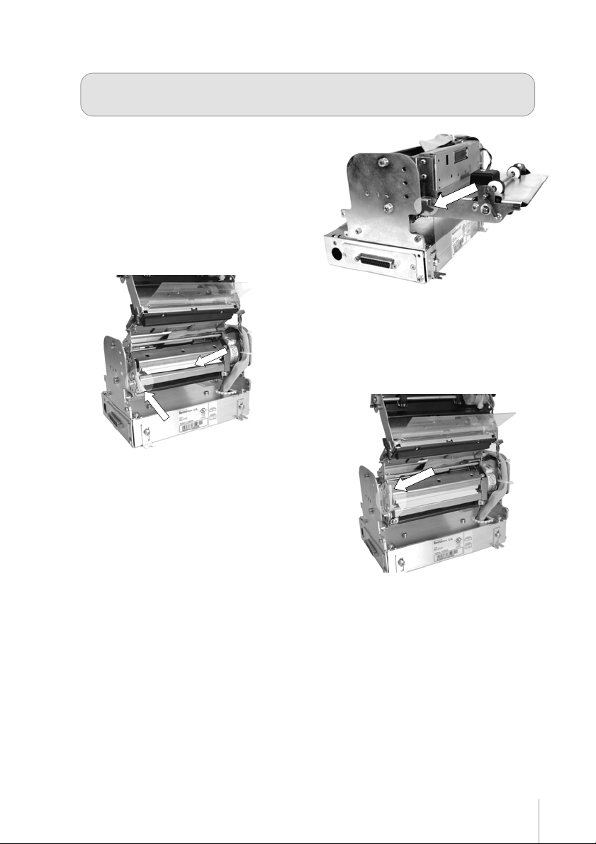
2. FRU90023 - FRU KC4112 PRES KIT
2.1 Remove the screws. (2x).
2.2 Pull in the sense of the arrows to remove. 2.3 Remove the screws. (2x).
30
FRU90023 - FRU KC4112 PRES KIT
Page 31

3. FRU90024 - FRU KC4112 TH MECH KIT
3.1 Cut to liberate the cables.
3.2 Remove the screws. (7x).
3.3 Remove the e-ring (1x).
FRU90024 - FRU KC4112 TH MECH KIT
31
Page 32

4. FRU90025 - FRU KC4112 CUTTER KIT
4.1 The process to loosen the cutter is the same of the presenter. (1.0 up to 1.6)
32
FRU90025 - FRU KC4112 CUTTER KIT
Page 33

5. FRU90026 - FRU KC4112 CTR BOARD DUAL
5.1 disconnect the cables
5.2 Remove the screws. (x4).
FRU90026 - FRU KC4112 CTR BOARD DUAL
33
Page 34

6. FRU90027 - FRU KC4112 CABLE KIT
6.1 Remove the screws to liberate the panel
of the parallel interface.
6.2 To set up the screws in the following
order
6.3 Remove the screws to liberate the panel
of the keyboard and key on/off.
34
Page 35

6.2 To set up the screws in the following order
6.2 To set up the screws in the following order
FRU90027 - FRU KC4112 CABLE KIT
35
Page 36

Chapter 12
Preventive MaintenancePreventive Maintenance
Preventive Maintenance
Preventive MaintenancePreventive Maintenance
Cleaning the Presenter:
Remove debris and paper dust from the presenter by using a vacuum cleaner, or by blowing or by using a dry soft
brush. Perform this operation when replacing paper roll.
Printer head cleaning procedure
Adhesion of dusts of paper and foreign materials may deteriorate the print quality and the lifetime of the head and
platen. When they adhere, clean the head according to the following procedures:
1. Take measures against static electricity such as a disposable wrist strap for the work.
2. Cleaning should be done with the presenter or the cutter (depends on your configuration) lifted up and
the platen part separated from the head (use the head-up lever).
Note: do not hit the thermal head surface with anything hard!
3. Wipe off the heating element part of the head surface lightly with cotton swabs to which Ethyl-alcohol
is applied. Be sure to clean the platen roll as well.
4. After Ethyl-alcohol has completely been dried, set the platen and perform the action check (print a self
test ticket and check the printing quality).
Note: do not use anything that may destroy the heating element, such as sandpaper. Do not apply
any unnecessary force to the thermal head.
Tests revealed that this procedure becomes necessary more often as the printer head gets used.
Lubrication:
Lubricate the presenter axle and bearings once a year, at least.
Clean axle and bearings, removing deposits of paper dust, aply the lubricant and remove any excess of oil.
Attention:
- Do not lubricate gears
- Use a high viscosity lubrificant. Low viscosity lubrificants are very likelly to be removed by force of axle
rotation
36
Page 37

See details on the lubrication points in figures below.
Parts to be cleaned and lubricated:
37
Page 38

Appendix A
FF
amily Codesamily Codes
F
amily Codes
FF
amily Codesamily Codes
KC-4112 is available with two options:
- With presenter and cut . (6200 - PB20 DRL1PR33 STACKED)
- Without presenter, with cut . (6300 - PB20 DRL1FC33 STACKED)
Custumers are not allowed to change the original configuration. This operation voids warranty terms, may
void the EMC and SAFETY certifications and may cause malfunction or injury. For further information, please
contact your dealer.
Identifying the kiosk printer model:
Check the four digits at the beggining of the serial number. They correspond to the printer model.
Ex.: SN 6200050612345 corresponds to:
• model 6200 (KC-4112, with presenter)
• Year (of manufacturing): 05 (2005)
• Month (of manufacturing): 06 (June)
• Sequencial: 12345
38
Page 39

Physical
Configuration *
Printer with presenter
(stacked version)
Dual
Height: 128.9 mm (5.03"")
Width: 184.4 mm (7.24"")
Depth: 230.8 mm (9.50"")
Weigth: 2.41 Kg (4.40 lbs)
Printer without
presenter (Stacked
Version)
Printer with presenter
(Low Profile)
Printer without
presenter
(Low Profile)
Printer with presenter
(Side Mount)
Printer without
presenter
(Side Mount)
Printer without
presenter
(Cut & Drop)
Paper Holder 6”/8”
Height: 128.9 mm (5.03"")
Width: 184.4 mm (7.24"")
Depth: 157.3 mm (6.18"")
Weigth: 2.13 Kg (4.40 lbs)
Height: 93 mm (3.66"")
Width: 184.4 mm (7.24"")
Depth: 315.8 mm (12.4"")
Weigth: 2.41 Kg (4.40 lbs)
Height: 93 mm (3.66"")
Width: 184.4 mm (7.24"")
Depth: 232.3 mm (9.13"")
Weigth: 2.13 Kg (4.40 lbs)
Height: 186 mm (7.32"")
Width: 244.3 mm (9.6"")
Depth: 223.7 mm (8.77"")
Weigth: 2.41 Kg (4.40 lbs)
Height: 186.0 mm (7.32"")
Width: 232.3 mm (9.13"")
Depth: 145.0 mm (5.7"")
Weigth: 2.13 Kg (4.40 lbs)
Height: 93 mm (3.66"")
Width: 184.4 mm (7.24"")
Depth: 216.7 mm (8.5"")
Weigth: 2.13 Kg (4.40 lbs)
Height: 123 mm (4.8”)
Width: 114,7 mm (4.5”)
Depth: 78 mm (3.1”)
Weight: 0.30 Kg (0.6 lbs)
* You are not authorized to change the printer configuration. This may void the EMC and Safety
certifications and may cause malfunction or injury. For further information, please contact your dealer.
39
Page 40

Appendix B
Field Replacement UnitField Replacement Unit
Field Replacement Unit
Field Replacement UnitField Replacement Unit
1. FRU90022 - FRU KC4112 PRESENTER FULL
2. FRU90023 - FRU KC4112 PRES KIT
3. FRU90024 - FRU KC4112 TH MECH KIT
40
Page 41

4. FRU90025 - FRU KC4112 CUTTER KIT
6. FRU90027 - FRU KC4112 CABLE KIT
5. FRU90026 - FRU KC4112 CTR BOARD DUAL
41
Page 42

Appendix C
Firmware UpdateFirmware Update
Firmware Update
Firmware UpdateFirmware Update
The kiosk printer has the capability to receive firmware updates from PC using ther RS-232 (COM1 or COM2) port.
This section explains the SW used to download FW to the kiosk printer.
Get the latest version of this SW at www.bematech.com/support
- Make sure that the printer is on and the cable (RS232) is correctly connected.
- Launch WinTest.exe
Printer Test
Boot Loader
Interfaces
File Name
C:\WinTesteMP\partial.bin
Output Window
Start Cancel
Clear Output Window
- Select the binary file (microcode) to download.
Open
Figure 59
42
Page 43

- The default interface is COM1 and baud-rate 115.200 bps.
Output Window
Clear Output Window
Boot Loader
Interfaces
Interfaces
USB
COM1
COM2
115200
Printer Test
- To choose other interface, select the interfaces TAB and changes interface.
Figure 60
- Select the boot loader TAB and click start button.
Printer Test
Boot Loader
Interfaces
File Name
C:\WinTesteMP\partial.bin
Output Window
Open
Start Cancel
Clear Output Window
Figure 61
43
Page 44

- The ERROR and PAPER LEDs on the kiosk printer start blinking.
- Use the Output Window to follow the update progress.
Printer Test
Boot Loader
Interfaces
File Name
C:\WinTesteMP\partial.bin
Start Cancel
57%
Open
Output Window
Clear Output Window
Figure 62
- The flash update will take a few seconds. Do not power off the printer or computer after the update has
started.
WinTestMP
Upgrade OK!
OK
Figure 63
- After the firmware update is complete the printer will be reset automatically.
44
Page 45

Appendix D
Assemblies
Control Board Box
45
Page 46

Printer Mechanism Module
46
Page 47

Presenter
47
Page 48

Stacked without Presenter
48
Page 49

Stacked with Presenter
49
Page 50

Low Profile with Presenter
50
Page 51

Low Profile without Presenter
51
Page 52

Side Mount with Presenter
Side Mount without Presenter
52
Page 53

Cut and drop
53
Page 54

Page 55

Page 56

 Loading...