

Page 1

Page 2

User’s Manual
KC-1800 User´s Manual
P/N: 6264 . Rev.1.1
August 2005
(First edition: July 2004)
Copyright© by Bematech S.A. Curitiba-PR, Brazil.
All rights reserved.
No part of this publication may be copied, reproduced, adapted or translated without the prior written permission
of Bematech S.A., except when allowed by patent rights.
Information in this publication is purely informative, subjected to change without notice and no liability is assumed
with respect to the use of this. However, as product improvements become available, Bematech S.A. will make
every effort to provide updated information for the products described in this publication. The latest version of this
manual can be obtained through Bematech website:
www.bematech.com
Notwithstanding the other exceptions contained in this Manual, the consequences and responsibility are assumed
by the Purchaser of this product or third parties as a result of: (a) intentional use for any improper, unintended or
unauthorized applications of this product, including any particular purpose; (b) unauthorized modifications, repairs,
or alterations to this product; (c) use of the product without complying with Bematech S.A. Corporation’s operating
and maintenance instructions; (d) use of the product as component in systems or other applications in which the
failure of this could create a situation where personal injury or material damages may occur. In the events
described above, Bematech S.A. and its officers, administrators, employees, subsidiaries, affiliates and dealers
shall not be held responsible or respond by any claim, costs, damages, losses, expenses and any other direct or
indirect injury, as well as claims which alleges that Bematech S.A. was negligent regarding the design or manufacture
of the product.
Bematech S.A. shall not be liable against any damages or problems arising from the use of any options or any
consumable products other than those designated as original Bematech products or approved products by
Bematech S.A.
Any product names or its logotypes mentioned in this publication may be trademarks of its respective owners and
shall be here recognized.
Product warranties are only the ones expressly mentioned in the User’s Manual. Bematech S.A. disclaims any
and all implied warranties for the product, including but not limited to implied warranties of merchantability or
fitness for a particular purpose. In addition, Bematech S.A. shall not be responsible or liable for any special,
incidental or consequential damages or lost profits or savings arising from the use of the product by the Purchaser,
the User or third parties.
2
Page 3

KC-1800 · Revision 1.1
EMC and Safety Standards Applied
Product Name: KC-1800
Model Name: 10000-XX (all)
*EMC is tested using an EPSON PS180 power supply
Europe:
CE marking
Safety: EN60950
North America:
EMI: FCC Class A
The use of non-shielded communication cables as well as unauthorized changes or modifications on the
equipment could void the certifications described in this page. Please contact your dealer for further information.
WARNING
CE Marking
The printer conforms to the following Directives and Norms:
Directive 89/336/EEC
EN 55022 Class B (Conducted and Radiated emission)
EN 55024
IEC 61000-4-2 ESD
IEC 61000-4-3 Radiated immunity
IEC 61000-4-4 EFTB
IEC 61000-4-5 Surge
IEC 61000-4-6 Conducted immunity
IEC 61000-4-11 Voltage Dips
FCC CLASS A
DECLARATION OF CONFORMITY
This equipment has been tested and found to comply with the limits for a Class A digital service,
pursuant to Part 15 of the FCC Rules. These limits are designed to provide reasonable protection against
harmful interference when the equipment is operated in a commercial environment. This equipment
generates, use and can radiate radio frequency energy and, if not installed and used in accordance with
the instruction manual, may cause harmful interference to the radio communications. Operation of this
equipment in a residential area is likely to cause harmful interference in which case the user will be
required to correct the interference at his own expense.
3
Page 4

User’s Manual
Safety Precautions
This section presents important information intended to ensure safe and effective use of this product. Please read
this section carefully and store it in an accessible location.
English
WARNING:
Immediately unplug the equipment if it produces smoke, a strange odor, unusual noise or if foreign matter including
water or other liquid falls into the equipment. Continued use may damage it or lead to fire *. Please contact your
dealer or a BEMATECH service center for advice.
Never attempt to repair this product yourself. Improper repair work can be dangerous.
Never disassemble or modify this product. Tampering with this product may result in injury or fire *.
Be sure to use the specified power source. Connection to an improper power source may cause malfunction or fire *.
CAUTION:
Do not connect cables in ways other than those mentioned in this manual. Different connections may cause
equipment damage and burning *.
Be sure to set this equipment on a firm, stable surface. The product may break or cause injury if it falls.
Do not install this equipment in locations that do not comply with the environmental requirements specified in this
manual.
Do not place heavy objects on top of this product. Never stand or lean on this product. Equipment may fall or
collapse, causing breakage and possible injury.
To ensure safety, unplug this product before leaving it unused for an extended period. In this case, please be sure
to place a piece of paper between the platen and the paper roll, in the thermal mechanism, to avoid damage when
restarting the printer.
* Note that this equipment was developed complying with international safety standards and therefore contains
only limited flammability components.
4
Page 5

KC-1800 · Revision 1.1
SummarSummar
Summar
SummarSummar
yy
y
yy
Chapter 1 - Foreword .................................................................................... 6
Chapter 2 - Technical Specifications KC-1800 ................................................... 7
Chapter 3 - Getting Started ............................................................................. 9
The Printer .............................................................................................................................. 9
Unpacking ............................................................................................................................... 10
Powering ................................................................................................................................. 11
Paper Handling ....................................................................................................................... 12
Key Panel .............................................................................................................................. 13
Error Table .............................................................................................................................. 14
Presenter Operation ................................................................................................................ 14
Operation Modes .................................................................................................................... 15
Chapter 4 - Communication Interfaces ............................................................. 16
Serial Interface ....................................................................................................................... 16
Parallel Interface ..................................................................................................................... 17
USB Interface ......................................................................................................................... 18
Chapter 5 - Dip Switch .................................................................................. 19
Chapter 6 - Troubleshooting ........................................................................... 20
Chapter 7 - Preventive Maintenance ................................................................. 21
5
Page 6

User’s Manual
Chapter 1
ForewordForeword
Foreword
ForewordForeword
The objective of this manual is to give to users all necessary information to properly operate the KC-1800 Printer
For further information refer to the documentation below available in our website:
www.bematech.com
Programmer´s Manual - Contains all necessary information to properly program and integrate the kiosk printer into
a system.
Outline drawings – Contains dimensions and assemblies.
6
Page 7

KC-1800 · Revision 1.1
Chapter 2
Technical Specifications KC-1800Technical Specifications KC-1800
Technical Specifications KC-1800
Technical Specifications KC-1800Technical Specifications KC-1800
Characteristics
Printing
Features
Communication
Power Requirements
Environment
Reliability
Media
Specifications
Method: Thermal Line Printing
Dot Density: 8 dots/mm (203 dpi x 203 dpi)
Print Width: 72 mm (2.83”) (576 dot-positions)
Print Speed: 80 mm/s (3.15”/s) (text mode)
Characters per line: 24, 32, 48 and 64
Character Set: Alphanumeric Code Page 850, Code Page 858, Code
Page 860 and Code Page 437
Modular, flexible and lightweight design
Automatic cutter (full and partial cut)
Presenter with retractable function
High reliability
Low paper sensor (paper near end)
Automatic paper loading
Downloadable firmware – update your printer software on site
Supported Barcodes: UPC-A, UPC-E, EAN13, EAN8, CODE 39, ITF, CODABAR,
CODE 93, CODE 128, ISBN, MSI, PLESSEY, PDF-417
Buffer Capacity: 32K Bytes
Interfaces: Parallel (Unidirectional) and Serial(RS-232) or USB (1.1)
Serial interface specification:
Baud rate: 9600 or 115200
Start bit: 1 bit
Data bits: 7 or 8 bits
Parity bit: odd / even or no parity
Stop bit: one or two bits
Voltage: 24 VDC ± 10%
Current: 2 A (4 A load, 1s max)
Operating temperature: 0 to +45ºC (+32 to +113°F)
Storage temperature: -20 to +60ºC (-4 to +140°F) (except for paper)
Operating humidity: 35 to 80% RH, non condensing
Storage humidity: 10 to 90% RH, non condensing (except for paper)
Print head ser vice life: 100 km, one hundred million pulses
Cutter lifetime: 500,000 cuts
Type: Single-ply thermal paper roll
Thickness: 67±5 um
Width: 79.0~80.0 mm (3.11~ 3.15”)
Roll diameter: External 8” (maximum) with internal 1” core. Please contact
your dealer for more details.
* Thermal side is on the outside of the roll
Recommended • TF50KS-E made by NIPPON SEISHI or equivalent
paper brand: • AF50KS-E made by JUJOTHERMAL
• KF50 made by KANZAN
• P350 made by KSP
7
Page 8
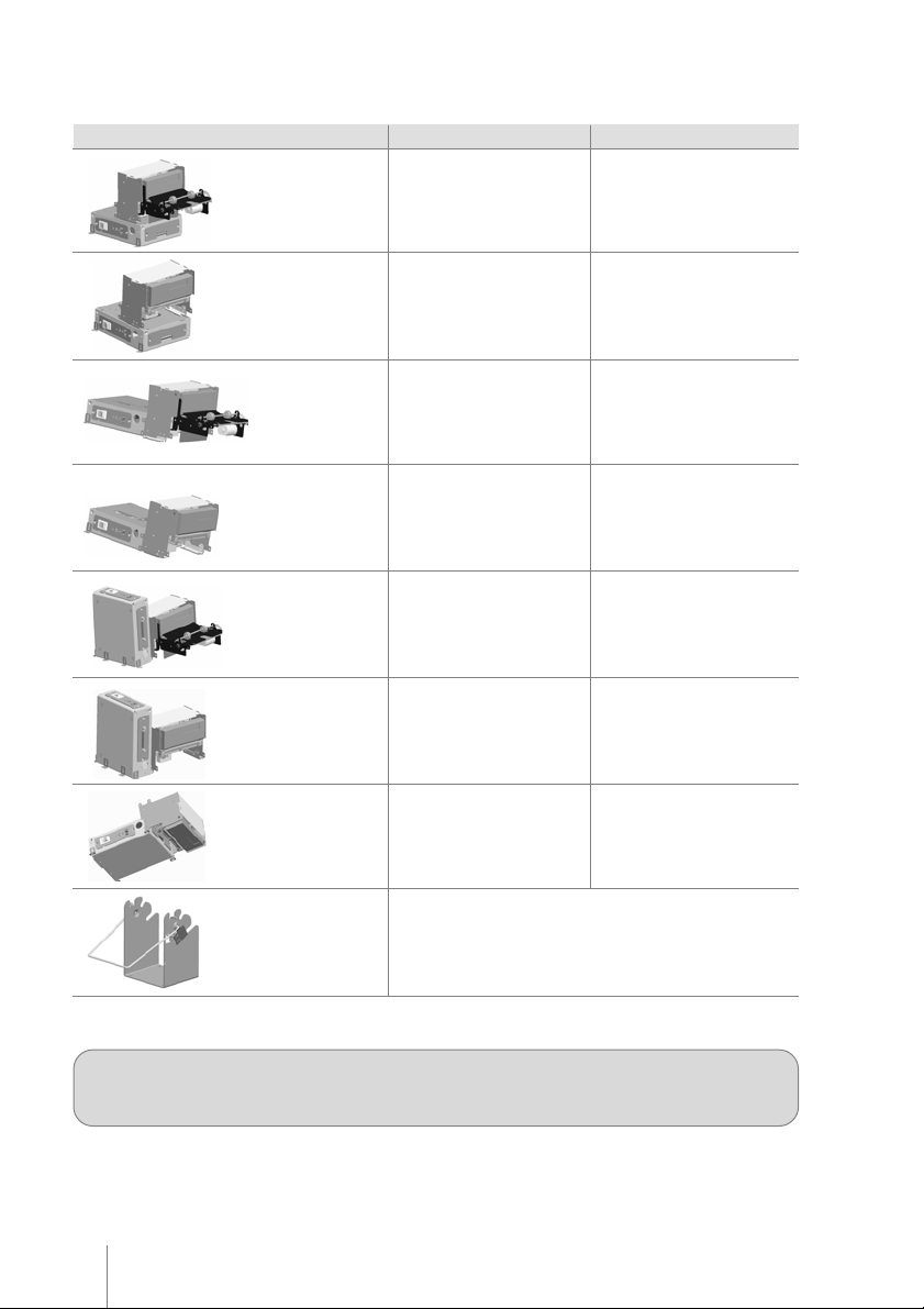
Physical
Configuration *
Printer with presenter
(stacked version)
Dual USB
Height: 138.1 mm (5.43"")
Width: 131 mm (5.15"")
Depth: 241.8 mm (9.51"")
Weigth: 1.78 Kg (3.92 lbs)
User’s Manual
Height: 138.1mm (5.43"")
Width: 131 mm (5.15"")
Depth: 232.8mm (9.16"")
Weigth: 1.78 Kg (3.92 lbs)
Printer without
presenter (Stacked
Version)
Printer with presenter
(Low Profile)
Printer without
presenter
(Low Profile)
Printer with presenter
(Side Mount)
Printer without
presenter
(Side Mount)
Printer without
presenter
(Cut & Drop)
Paper Holder 6”/8”
Height: 138.1 mm (5.43"")
Width: 130 mm (5.11"")
Depth: 161.8 mm (6.37"")
Weigth: 1.55 Kg (3.41 lbs)
Height: 96 mm (3.77"")
Width: 136.3 mm (5.36"")
Depth: 305.2 mm (12.01"")
Weigth: 1.75 Kg (3.85 lbs)
Height: 96 mm (3.77"")
Width: 136.3 mm (5.36"")
Depth: 225.3 mm (8.87"")
Weigth: 1.50 Kg (3.30 lbs)
Height: 147 mm (5.78"")
Width: 187.9 mm (7.39"")
Depth: 223 mm (8.77"")
Weigth: 1.78 Kg (3.92 lbs)
Height: 147 mm (5.78"")
Width: 187.9 mm (7.39"")
Depth: 143 mm (5.62"")
Weigth: 1.55 Kg (3.41 lbs)
Height: 85.5 mm (3.36"")
Width: 130 mm (5.11"")
Depth: 226.3 mm (8.9"")
Weigth: 1.55 Kg (3.41 lbs)
Height: 123 mm (4.8”)
Width: 114,7 mm (4.5”)
Depth: 78 mm (3.1”)
Weight: 0.30 Kg (0.6 lbs)
Height: 138.1mm (5.43"")
Width: 130mm (5.11"")
Depth: 152.8mm (6.01"")
Weigth: 1.55 Kg (3.41 lbs)
Height: 96mm (3.77"")
Width: 136.3mm (5.36"")
Depth: 296.2mm (11.66"")
Weigth: 1.75 Kg (3.85 lbs)
Height: 96mm (3.77"")
Width: 136.3mm (5.36"")
Depth: 216.3mm (8.51"")
Weigth: 1.50 Kg (3.30 lbs)
Height: 147mm (5.78"")
Width: 187.9mm (7.39"")
Depth: 214mm (8.42"")
Weigth: 1.78 Kg (3.92 lbs)
Height: 147mm (5.78"")
Width: 187.9mm (7.39"")
Depth: 134mm (5.27"")
Weigth: 1.55 Kg (3.41 lbs)
Height: 85.5mm (3.36"")
Width: 130mm (5.11"")
Depth: 217.3mm (8.55"")
Weigth: 1.55 Kg (3.41 lbs)
* You are not authorized to change the printer configuration. This may void the EMC and Safety certifications
and may cause malfunction or injury. For further information, please contact your dealer.
8
Page 9

KC-1800 · Revision 1.1
Chapter 3
Getting StartedGetting Started
Getting Started
Getting StartedGetting Started
The Printer
The communication connectors, DC connector, On/Off switch and key panel can be found in different locations of
the printer, according to the selected assembly.
Cutter
Presenter
Paper entrance
Parallel Port connector
Figure 1
PNE sensor cable
DC connector
Serial connector
DC connector
(optional)
Key panel
On/Off switch
Figure 2
9
Page 10

Paper holder
Damping device
Figure 3
Unpacking
Take the printer out of its box and verify that the following items are included:
• Printer
• User´s Manual
Keep the box and packing materials for future use if necessary.
User’s Manual
Spindle
Paper near end sensor
Paper roll is not included – the appropriate thermal paper should be used. Refer to the Technical
Specifications section in this manual for paper details.
10
Page 11

KC-1800 · Revision 1.1
Powering
Make sure that the printer is turned off. Connect the power cord to the power supply‘s AC connector and to an
electrical outlet. This outlet must have its ground pin connected as shown on the right:
GROUND
Figure 4
Connect the DC cable of the power supply in the printer as shown below – note that the arrow in the connector must
be facing down:
DC
connector
Figure 5 Figure 6
Turn on the printer using the on / off switch located on the printer. Check, also in the panel, if the Power LED is lit.
If no paper is present, the Paper LED will also be lit.
DC Cable Specification:
Connector
A
C
B
Figure 7
Specification
A
24VDC
B
C
GND
N.C.
C
A
B
Figure 8
11
Page 12

Paper Handling
Loading Paper
To insert a new paper roll, please do as follows:
The end of the paper roll must be
cut evenly, as shown on the right.
Be sure that the presenter is in the
locked position.
Place the spindle in the paper roll’s
core and then place the roll and
spindle in the paper holder as shown
in figure 10.
Note that the paper must go under
the damping device.
User’s Manual
Figure 9
Gently push the paper into the paper
entrance. The printer will
automatically pull the paper,
perform a paper cut, and turn off the
Paper LED.
12
Figure 10
Figure 11
Page 13

KC-1800 · Revision 1.1
Removing Jammed Paper
Note: If the cutter remains blocked due to a paper jam, unplug the printer and use the manual lever to move
the cutter blade prior to perform the steps below.
If a paper jam occurs, follow the steps below:
1. Cut the paper at the paper entrance.
Presenter Lock
Figure 12
2. Push down the Presenter lock (Figure 12)
and gently move the Presenter as indicated
(Figure 13).
Figure 13
3. Unlock the head up switch raising the print head
(Figure 14).
4. Gently pull the paper out of the mechanism.
Figure 14
5. Lock the head up switch and bring the Presenter back to the inicial position. Lock the Presenter.
Key Panel
The key panel gives visual printer status and manual control to the operator.
These functions are accomplished using one switch and LEDs, described below:
• POWER LED: This green LED will be on whenever power is applied to the printer and the power switch is on.
• PAPER LED: This red LED will be on when the printer is without paper. If the print head is up, this red LED
will blink.
• ERROR LED: This red LED will blink in error conditions. See ERROR TABLE on next page.
• PAPER FEED BUTTON: Use to feed paper line by line with fast button touches or feed paper continuously, by
pressing and holding down the button.
13
Page 14

Error Table
User’s Manual
Error
Mechanism
Power Supply
Cutter
Printer Head
Temperature
Entrance Presenter jam
Exit Presenter jam
Number
of Blinks
8
11
12
15
16
16
Type
Non-recoverable
Non-recoverable
Non-recoverable
Recoverable
Non-recoverable
Non-Recoverable
Possible cause
Thermal Head is damage or Thermal Head
cable is disconnected
Power supply voltage below 20V
Cutter can not cut the paper
When printing long or too dark graphics
Paper did not enter in the presenter
Presenter can not eject the paper
Presenter Operation
The presenter mechanism is responsible for the ejection of the receipts printed by the kiosk printer. It is designed
so that paper jam probability is minimized. However, due to paper feed conditions (wrong paper feeding, paper
wrinkles etc.) paper jam may occur, especially when replacing paper. We may, then, consider the following:
• When a paper jam occurs in the presenter entrance, the paper will not reach the presenter sensor (located in
the presenter cover) – in this case, the kiosk printer goes into error condition, thus requiring manual intervention.
After removing the jammed paper (see “Removing Jammed Paper” on page 13), the printer must be turned off
and on again, in order to the printer to come back on line.
• When the paper jam occurs in the presenter paper exit, the kiosk printer will try to force the paper out for 8
seconds. If that does not happen, the printer will wait for 10 seconds, after which it will try a new paper
presenting sequence. If the second try is not effective, the printer will go permanently in error condition, thus
requiring a manual intervention to remove the paper. Note that this paper jam may occur while replacing paper
or if there is vandalizing of the paper exit. In addition, and in order to prevent that, the presenter has a clutch
device that prevents paper jamming if paper exit is blocked.
Retractable Function
It is possible to set the retractable function by command. If this feature is enabled, after a full cut command the
presenter will push the paper and return it to its sensor. By default, if the paper remains below the sensor during
10 seconds, the presenter will pull the paper automatically. The retractable delay can also be programmed by
command. The printer is prepared mechanically to pull the paper avoiding receipt jam.
Reliability of presenter operation without the recommended paper is not guaranteed.
14
Page 15

KC-1800 · Revision 1.1
Operation Modes
The printer can be operated in the following modes:
Normal (Remote mode)
In this state, the printer is being controlled by the host through the serial, parallel or USB interfaces.
Dump mode
In this mode advanced users and programmers can identify communication problems between the host and the
printer or check if a certain programmed data is correctly being sent to the printer, thus being a debugging tool. To
start the hexadecimal dumping, turn on the printer while pressing the paper feed switch. A message will be
printed on the paper asking you to press once more the paper feed switch if Dump mode is desired, as shown:
- Press PAPER switch once for DUMP MODE
Self-testing
To run a self-test, turn the printer off. Press and hold the Paper Feed switch and turn it on. When the printer starts
printing, the paper feed button can be released. A message will be printed asking you to wait the self-test. In the selftest you will find the printer firmware version, among other information.
15
Page 16

User’s Manual
Chapter 4
Communication InterfacesCommunication Interfaces
Communication Interfaces
Communication InterfacesCommunication Interfaces
Communication between a host and the printer can be performed in three communication protocols: USB, Parallel
or Serial RS-232, according to the printer model.
Communication cables are not supplied with the printer
Serial Interface
The RS232 serial interface uses a female DB-25 connector. The serial port can operate using the DTR/DSR mode,
with 7 or 8 data bits, with or without parity, even or odd parity, one start bit and one or more stop bits. In the
RS232 standard, the logic low level corresponds to a +12V voltage level and a logic high level corresponds to -12V.
DTR / DSR mode
In this mode, the printer’s DTR line controls the flow of data sent from the host’s TX line and received by the
printer’s RX pin. In this case, when the printer’s DTR signal is low (+12V) the printer requests the host to send
data. When the DTR signal is high (-12V) the printer tells the host to stop sending data.
DB-25 Serial connector
03
.................13.................12.................11.................10.................09.................08.................07.................06.................05.................04.................
.............24.............23.............22.............21.............20.............19.............18.............17.............16.............
25
Figure 15
The serial cable needed for the DTR / DSR mode is shown below:
Printer Side (DB-25) Host Side (DB-9)
2 (TD) 2 (RD)
3 (RD) 3 (TD)
6 (DSR) 4 (DTR)
7 (GND) 5 (GND)
20 (DTR) 6 (DSR)
Printer Side (DB-25) Host Side (DB-25)
2 (TD) 3 (RD)
3 (RD) 2 (TD)
6 (DSR) 20 (DTR)
7 (GND) 7 (GND)
20 (DTR) 6 (DSR)
16
1-7-8 (jumper)
4-5-8 (jumper)
Page 17

KC-1800 · Revision 1.1
Parallel Interface
The unidirectional parallel interface has the following specifications:
• Synchronization: Externally supplied Strobe signal
• Handshaking: Ack and Busy signal
• Signal levels: TTL compatible
• Data transmission: 8-bit parallel
Parallel Interface Pin Assignments
.................17.................16.................13.................12.................11.................10.................09.................08.................07.................06.................05.................04.................03.................02.................
.............35.............33.............32.............31.............30.............29.............28.............27.............26.............25.............24.............23.............22.............21.............20.............19.............
36
Figura 16
01
Signal pin
1
2
3
4
5
6
7
8
9
Associated
return pin
19
20
21
22
23
24
25
26
27
Signal
/STROBE
Data 1
Data 2
Data 3
Data 4
Data 5
Data 6
Data 7
Data 8
Direction
IN
IN
Description
Strobe pulse for data reading. The pulse’s width
must be larger than 0.5 us.
Data in signals (LSB is Data 1). The signal high
level corresponds to bit 1 and the low level
corresponds to 0.
17
Page 18

User’s Manual
Signal pin
10
11
12
13
14,15,18,36
16
17
19-30
31
32
33
34
35
Associated
return pin
28
29
30
Signal
/ACK
BUSY
PE
OL OUT
NC
GND
Frame
GND
/INIT
/ERROR
GND
NC
PULLUP
Direction
OUT
OUT
OUT
OUT
IN
OUT
OUT
Description
This pulse is active low and indicates that data
sent to the printer has been received. The pulse
width must be larger that 10us.
When high, indicates that the printer cannot
receive data.
Becomes high in case of:
1 – Paper end.
0 – Near paper end.
On line Out. When high, indicates operation in
remote mode. When low, indicates operation in
local mode.
Not connected.
Circuit ground.
Frame ground.
Circuit ground.
When low initializes the printer. It may be larger
than 50us.
Paper absence.
Circuit ground.
Not connected.
“Pulled Up” to +5V
USB Interface
The USB interface is compatible with the Universal Serial Bus Specification 1.1. It is a 12 Mbps serial channel using
the Bulk mode with a “B” receptacle as show below. The USB cable must have in one side an “A” plug to connect
in the host, and in the other side an “B” plug to connect in the printer. The printer is self-powered and does not draw
power from the standard type B USB interface cable.
Type “B” Receptacle
2 1
3 4
Figure 17
Using the USB interface, the printer can be connected to the host even if both parts are powered. The first time you
connect the printer to the host, the operation system will ask for the printer driver. Please download the latest printer
driver from our website (www.bematech.com). For more details please contact your dealer.
18
Signal pin Signal
1NC
2DATA+
3DATA -
4 GND
Page 19

KC-1800 · Revision 1.1
Chapter 5
Dip SwitchDip Switch
Dip Switch
Dip SwitchDip Switch
One set of dip switches is mounted in the control board of the KC-1800. To access these dip switches, please do
as follows:
• Turn off the printer
• Remove the paper from the mechanism
• Remove the screws that hold the cover of the control board
• Using the tables below, change the configuration of the dip switches
• Mount the cover of the control board and fasten the screws back
Dip Switch Function
1 Baud Rate On: 115200 bps
2 PNE** On: activated
3 Reserved Must be in off position
4 Stop Bits On: 1 stop bit *
5 Character leght On: 7 bits
6 Parity Select On: Odd
7 Parity On: not used *
8 Presenter On: activated ***
* Default
*** Default for printers with presenter
**** Default for printers without presenter
** ON - Default or :
After Esc m: PNE sensor is returned in status bit (serial or USB) or PE line (Parallel)
After Esc l: Presenter sensor is returned in status bit (serial or USB) or PE line (Parallel)
OFF - Default or after Esc m: always return paper ok
After Esc l: always return paper ok
Off: 9600 bps *
Off: not activated
Off: 2 stop bits
Off: 8 bits *
Off: Even *
Off: used
Off: not activated ****
19
Page 20

User’s Manual
Chapter 6
TT
rr
oubleshootingoubleshooting
T
r
oubleshooting
TT
rr
oubleshootingoubleshooting
The following table described some of the problems that might occur while using the printer. For ever y problem
there is a possible cause described here and a suggested procedure to solve the problem.
Problem
The printer does not turn on.
The printer does not respond
to the commands sent.
Parallel communication is
faulty.
Serial communication is faulty.
Possible Cause
There is no power in the electric
outlet.
A problem with the power cord – it
may be broken or not well
connected to the printer and / or
outlet.
The parallel / serial / USB cable has
one or more lines with faulty
connections / broken wires.
Wrong programming sequences.
The parallel cable has one or more
lines with faulty connections /
broken wires.
The pin layout does not follow the
Centronics standard.
The serial cable has one or more
lines with faulty connections /
broken wires.
The pin layout does not follow the
correct protocol.
The baud rate is incorrectly set.
Possible Cause
Check if there is a central switch for
the room / outlets. Connect some
other equipment to the outlet to
check its operation.
Turn off the printer, check the power
cord’s continuity and a perfect
connection between the printer and
the electric outlet.
Check for a good connection
between the printer and the host or
change the cable.
The programming sequences can be
checked in the dump mode. Put the
printer in dump mode and run your
application again. The printer will
show the hexadecimal and ASCII
codes of all bytes being received
from the host.
Check for a good connection
between the printer and the host or
change the parallel cable.
Check the correct pin layout in this
manual.
Check for a good connection
between the printer and the host or
change the serial cable.
Check if the pin layout used
complies with the protocol being
used for data transmission.
Remember that the printer uses the
DTR/DSR protocol.
If the baud rate set on the printer is
different from the baud rate of the
host, the printer will print random
characters or not print at all. Check
carefully the host’s serial baud rate
configuration as well as the printer’s
DIP switch settings.
20
Page 21

KC-1800 · Revision 1.1
Chapter 7
Preventive MaintenancePreventive Maintenance
Preventive Maintenance
Preventive MaintenancePreventive Maintenance
Cleaning the Presenter:
Remove debris and paper dust from the presenter by using a vacuum cleaner, or by blowing or by using a dry soft
brush. Perform this operation when replacing paper roll.
Printer head cleaning procedure:
Adhesion of dusts of paper and foreign materials may deteriorate the print quality and the lifetime of the head and
platen. When they adhere, clean the head according to the following procedures:
1. Take measures against static electricity such as a disposable wrist strap for the work.
2. Cleaning should be done with the presenter or the cutter (depends on your configuration) lifted up and
the platen part separated from the head (use the head-up lever).
Note: do not hit the thermal head surface with anything hard!
3. Wipe off the heating element part of the head surface lightly with cotton swabs to which Ethyl-alcohol
is applied. Be sure to clean the platen roll as well.
4. After Ethyl-alcohol has completely been dried, set the platen and perform the action check (print a self
test ticket and check the printing quality).
Note: do not use anything that may destroy the heating element, such as sandpaper. Do not apply
any unnecessary force to the thermal head.
Tests revealed that this procedure becomes necessary more often as the printer head gets used.
21
Page 22

Page 23

Page 24

 Loading...