

Beltronics Express 795 Owner's Manual
Express
795
795
BELTRONICS INCORPORATED
5442 West Chester Road
West Chester Ohio
45069 USA
USA 800-341-2288
www.beltronics.com
©2005 Beltronics
Designed and Manufactured in Canada
Features and specifications are prices subject to change without notice.
Other Patents Pending.
Model: E795
RADAR•LASER DETECTOR
Owner’s Manual
fo
r p
o
sitio
n
o
n
ly
121E795-0
17262_795_Manual 1/24/05 9:14 PM Page 1
32
CONGRATULATIONS!
The BEL Express 795 is a value-priced radar and laser
detector, with all the performance you’d expect from
BELTRONICS - the technology leader.
The Express 795 includes outstanding performance
against all X, K, SuperWide Ka, radar and laser guns,
Digital Signal Processing (DSP) for increased range and
reduced false alarms, and is packed with these userfriendly features:
•Digital Power On/Off
• Power-On Indicator
•City Mode Indicator
•Separate X/K/Ka LED band indicators
• 4-LED Signal Strength Meter
• Unique audible tones for each band
•Digital Brightness Control
• Auto and Manual Mute
• Modular Power Cord
In order to get the most out of your Express 795, please
read the entire owner’s manual. Please drive safely.
TABLE OF CONTENTS
Listing of Features ➤ page 4
Operation
Start-Up Sequence ➤ page 6
Memory Retention for Preferred Settings ➤ page 7
Setting the Audio Level ➤ page 7
Mute and AutoMute Modes ➤ page 8
Confirming Volume Level ➤ page 8
Audio Alerts ➤ page 8
“Instant On” Audio/Visual Alerts ➤ page 9
Brightness Control ➤ page 9
City Button ➤ page 9
Installation
Important Information ➤ page 10
Windshield Mount ➤ page 10
Care of Your Detector ➤ page 12
Power Connection ➤ page 12
Troubleshooting Guide ➤ page 13
Service Procedure ➤ page 13
Modifications not expressly approved by the manufacturer
could void the user’s FCC granted authority to operate the
equipment.
17262_795_Manual 1/24/05 9:14 PM Page 2
4 5
ADVANCED FEATURES
• Super Wideband Ka-band detection: Digital sweep
circuits cover the entire bandwidth- 33.4 to 36.0 GHz.
• VG-2 Guard
®
: Alerts to the presence of the RDD (Radar
Detector Detector). Note: Express 795 is factory shipped
with this feature OFF.
➣ To activate VG-2 Guard®, press CITY and BRT
buttons when the unit is ON. The Ka indicator
will illuminate coupled with the flashing of the
first red signal strength LED.
➣ Press the VOLUME/MUTE button to engage/
disengage the VG-2 Guard®feature.
➣ Press the PWR button to exit this mode, and
Express 795 will be ON.
➣ An encounter with the Interceptor VG-2 will
trigger a unique audio tone, and the illumination
of the first red signal strength LED followed by
the fourth red signal strength LED. This type
of audio/visual alert confirms traffic is being
monitored. Your Express 795 will not be detecting
radar or laser during this alert pattern. When the
alert is over, your unit resumes scanning for radar
and laser.
Note: Activate VG-2 Guard only when Interceptor VG-2 is
known to be in use.
• Total Tracking Laser™ (TTL™): Multiple laser sensors
provide optimum performance and the widest “field-ofview”.
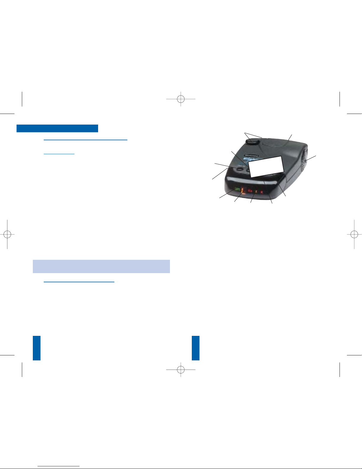
1. PWR Button: Press this button to turn the detector on/off
(see page 7).
2. Power-on Indicator: A single green LED illuminates to
indicate the detector is receiving power.
3. CITY Button: Press this button to activate City Mode.
Press it a second time to deactivate it. (See page 0).
4. City Mode Indicator: A single green LED illuminates
when the City Mode filter mode is activated. (See page 0)
5. BRT Button: Press this button once to dim the Band
Indicator, Power-On, City, and Signal Strength LEDs.
Dark Mode is accessed by pressing it a second time. In
Dark Mode, the Band Indicator, City and Signal Strength
LEDs will be off. The Power-On indicator will be changed
to a very dim state. Audio alerts are not affected (see
page 0).
6. X/K/Ka Visual Indicators: There are separate visual
indicators (LEDs) for X, K and Ka band radar.
7. Radar Signal Strength: Relative signal strength for all
radar signals is displayed by four red LEDs. These red
LEDs ramp left to right as you get closer to the radar
source.
8. Laser Alert: When a Laser signal is detected, all of the
radar LED indicators (X/K/Ka) will illuminate, in conjunction with the flashing of the 4 red signal strength LEDs in
an alternating pattern (outer two LEDs followed by the
inner two LEDs).
5
9
8
10
7
6
4
3
11
2
1
F. P. O .
17262_795_Manual 1/24/05 9:14 PM Page 4
 Loading...