

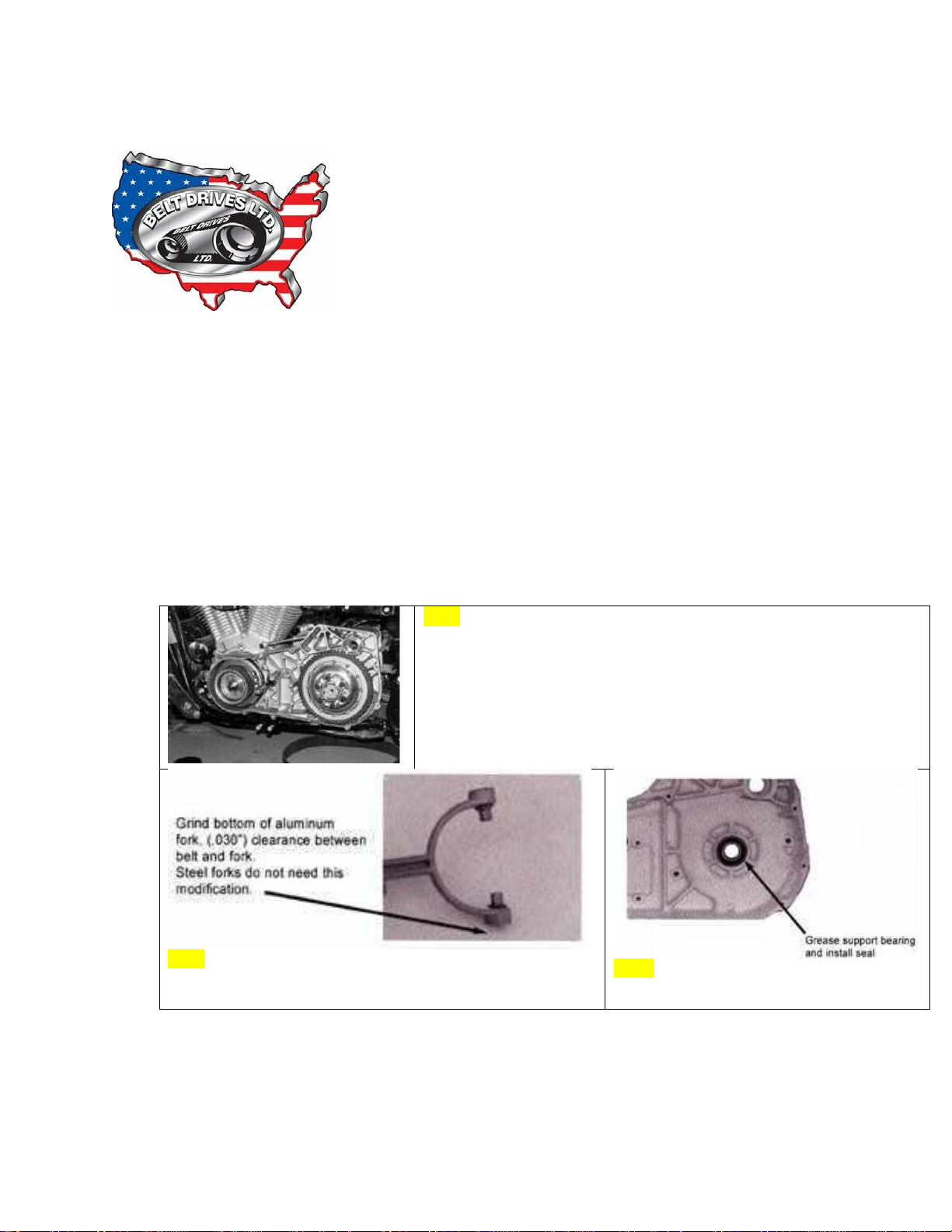
Fig.1- Install pulleys and check for fit; some clearance may be
INSTALLATION FOR BOLT IN BELT DRIVES (1986-UP MODELS)
(Kit Numbers: EVB-1T, EVB-1S, EVB-1SL, EVB-2T, EVB-2S)
Be sure to read the Warranty, Introduction, belt tracking and starter gear problems, alignment procedure
and disconnect battery.
1. Remove springs, shoulder bolts and clutch plates from clutch basket. This makes installation
easier.
2. Install front and rear pulleys and check for clearance. At this time you should determine if the
front pulley will need shimming or not depending on how the pulleys align with each other.
Remove pulleys and make any modifications if necessary. (Fig.1)
3. Grease the support bearing and install seal included with kit OR remove inner primary and install
sealed inner primary bearing (see Fig. 4) also s
E: You must remove the mainshaft inner bearing race from the transmission mainshaft. This
NOT
is a sleeve type race that is pressed onto the mainshaft.
upplied with kit. (See note below)
necessary. Also, check for alignment to determine if shimming may
be necessary behind front pulley.
Fig.2- On early FXR’s, you may have to grind bottom of
starter fork, alumin u m fork only.
Fig. 3
1
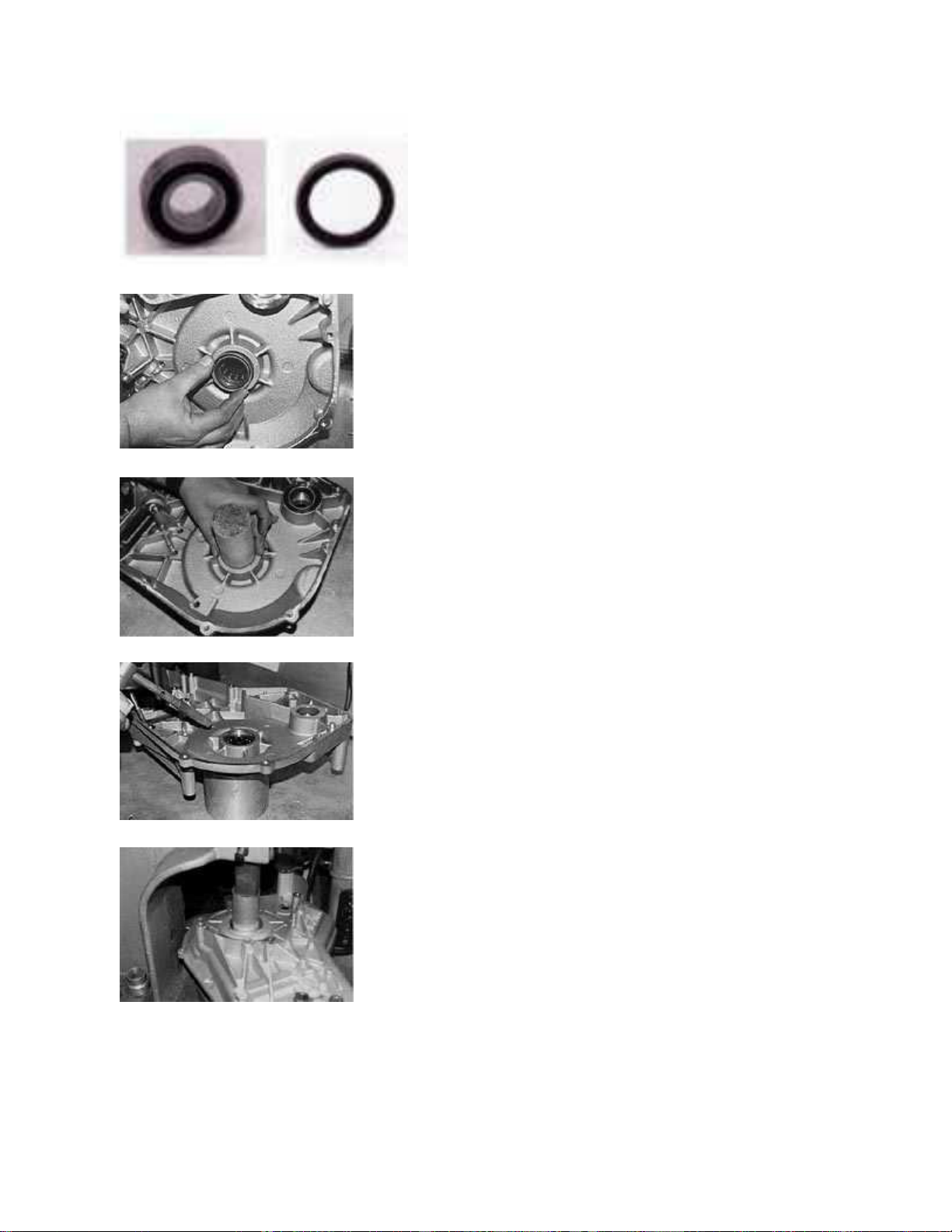
Fig. 4 BDL includes a sealed primary bearing to replace stock support bearing.
If you are using the stock bearing, then install enclosed seal, flat side facing in.
Grease bearing and install seal. It may be easier to use a solid bar to press seal into
place. It may be necessary to re-pack bearing and replace seal during yearly
maintenance.
If you are going to remove the stock bearing and use the sealed bearing , then remove
primary, remove retaining rings and heat area around bearing for removal.
Press stock bearing out of the primary.
2

Freeze sealed bearing and re-heat area around bearing housing, the bearing should fall
into place without a problem. Replace retaining ring.
4. Make sure motor & transmission shafts are square with each other. (Refer to section on Alignment procedure)
Clean mainshaft spline area so that there is no oil residue to interfere with the Loctite® bonding.
5. For spline mainshaft models, 1990-up, apply red Loctite® into the back side of our hub inside of the spline and
let the Loctite® flow onto the mainshaft when sliding the rear basket assembly on. (Fig. 5)
Fig. 5 Apply red Loctite® to spline hub before installing it onto mainshaft. This is for
1990-up models only.
This procedure is necessary so that the hub and mainshaft will fit together properly and will not let the mainshaft
spin inside of our hub. (This procedure is not necessary on taper shaft models 1986-89)
Failure to Loctite® the splined hub properly will cause the splines to wash out.
6. If front pulley shimming was necessary be sure that the shims are in place, now install rear pulley, belt and
front pulley at the same time. (Fig. 6)
Fig. 6 Install both pulleys and belt at the same time.
Engine shaft spline should not protrude from pulley. (Fig. 7)
Fig. 7 If engine shaft spline protrudes as pictured, a washer is needed to compensate for protrusion
of spline before washer and nut is installed.
3

7. Rotate the motor by hand using a socket wrench, the belt should track straight and away from motor but not
off of the front pulley. Be sure to red loctite front engine nut and torque to HD specifications. (Electric impact is
preferred). (Fig. 8)
Fig. 8
8. Apply Loctite® to and install and tighten to HD specifications, mainshaft hub nut. We supply a special hub nut
with seal for all spline shaft models 1990 and later.
9. Install sealed mainshaft nut supplied with 1990-up kits only. For 1986-89 you must use stock hub nut and the
seal kit enclosed with kit. For Shovelhead you must use the stock hub nut with seal. Apply Loctite® to nut
before installation. (Fig. 9)
Fig. 9 Install sealed mainshaft nut supplied with 1990-up kits only. For
1986-89 you must use stock hub nut and the seal kit enclosed with kit.
For Shovelhead you must use the stock hub nut with seal. Apply Loctite®
to nut before installation.
Pictured here is the seal kit installation which is supplied
with all 1986-89 belt drives only. A sealed hub nut is
supplied with all kits 1990- up. A stock HD hub
nut with seal must be used with all 1983 and earlier kits.
10. Install clutch pack, refer to schematic (below) spline steel first, 1/2 sided friction plate with fiber facing out,
then alternate steel and two sided fiber plates ending with the other 1/2 sided friction plate with fiber facing in. If
4

your kit contains the new Quiet clutch then refer to the lower diagram below. Install pressure plate, springs and
shoulder bolts.
To install shoulder bolts apply red Loctite® to a bolt and install it one turn, go on to the next bolt with same
procedure until all 6 bolts are in place, then tighten them all the way down until they bottom out. There is no
adjustment to the spring pressure, this is all pre-determined with the length of the shoulder bolt and exact
dimensions of our pressure plate. (Fig. 10)
11. Clutch screw adjustment should be approximately 1/4 turn loose from lightly seated. (Note when clutch is
hot the adjustment screw should not be seated). Tighten rod nut when adjustment is complete. (We supply a
clutch adjusting rod and nut for all models 1990-up only). (Fig. 11. 11a)
Fig.11 Install clutch adjusting rod supplied with kit 1986-up. and adjust clutch.
Fig. 11a Finished installation. Be sure to check clearance of outer cover to drive.
5

12. Install outer primary cover with gasket and check for clearance between drive and cover. Tighten all bolts to
HD specifications. (Fig. 12)
Fig. 12 Install outer primary cover with gasket
Note: We do not supply a sealed hub nut or adjusting screw and nut on 1986-89 models. You must use the stock
adjusting screw and nut and stock hub nut with ESK-1 seal kit provided in the kit.
6
 Loading...