

Page 1

Thermoglaze
TG 25
Operator’s Manual
Belshaw Bros., Inc.
814 44th Street NW, Suite 103
Auburn, WA 98001 USA
Phone: (206) 322-5474 • Fax: (206) 322-5425
Email: service@belshaw.com • http://www.belshaw.com
Page 2

Page 3

Congratulations on buying a new
Thermoglaze from Belshaw Bros., Inc. Please
inspect the unit carefully for damage or
missing pieces immediately after receiving
your system. Belshaw cannot pay for shipping
damage, because the freight company has
accepted the machine from Belshaw in good
condition, and is responsible for its safe delivery.
For your protection, each crate should be
inspected before signing the Bill of Lading to
report any visible damage caused by the
trucker in transit, and account for the number
of crates.
EQUIPMENT RECORD
Please provide the information below when you correspond with us about your machine.
Purchased by _____________________________________________________________________
Installed by ______________________________________________________________________
Date of Installation ________________________________________________________________
Model number ___________________________________________________________________
Serial number
011108
MN-1727EN
Belshaw Bros., Inc.
814 44th Street NW, Suite 103
Auburn, WA 98001 USA
Phone: (206) 322-5474 • Fax: (206) 322-5425
Email: service@belshaw.com • http://www.belshaw.com
Page 4

Page 5

Contents
1 Operation 1
Operating the Thermolizer 2
Thermoglaze 25 Symbol Key 3
6 Cleaning 4
Daily TG Cleaning Instructions 4
Thermolizer Cleaning Instructions 11
Belshaw Bros., Inc. • www.belshaw.com • Phone 206-322-5474 • Fax 206-322-5425
Thermoglaze 25 OM MN-1727EN iii
Page 6

Preface
The operator of the Thermoglaze is expected to
behave safely, read this manual before operation,
and follow its instructions and warnings.
Study the instructions and warnings in this
manual carefully before operating the equipment.
A thorough understanding of how to install,
maintain, and safely operate the Thermoglaze
will prevent production delays and injuries. Prior
operation of the equipment before reading and
understanding the instructions in the manual will
void the warranties of the equipment.
To use the Thermoglaze safely, heed the
following warnings and all other warnings that
appear in this manual:
• To avoid damaging the Thermoglaze,
never use force to assemble,
disassemble, operate, clean, or maintain
it.
Belshaw Bros., Inc. • www.belshaw.com • Phone 206-322-5474 • Fax 206-322-5425
iv MN-1727EN Thermoglaze 25 OM
Page 7

Operation 1
• Turn on main power switch and allow to heat
to operating temperature. (Note: Heat light
will go out when oven reaches
temperature.)
• Turn on the Thermoglaze and heat for 30
minutes to allow it to reach operating
temperature.
• Load glaze reservoir with 20 pounds (one
small bucket) of glaze and turn on the glaze
pump.
WARNING
Use proper lifting technique when lifting
glaze buckets to avoid back injury.
WARNING
Do not operate glazer without glaze or water
in the pump. Doing so can cause permanent
damage to the pump.
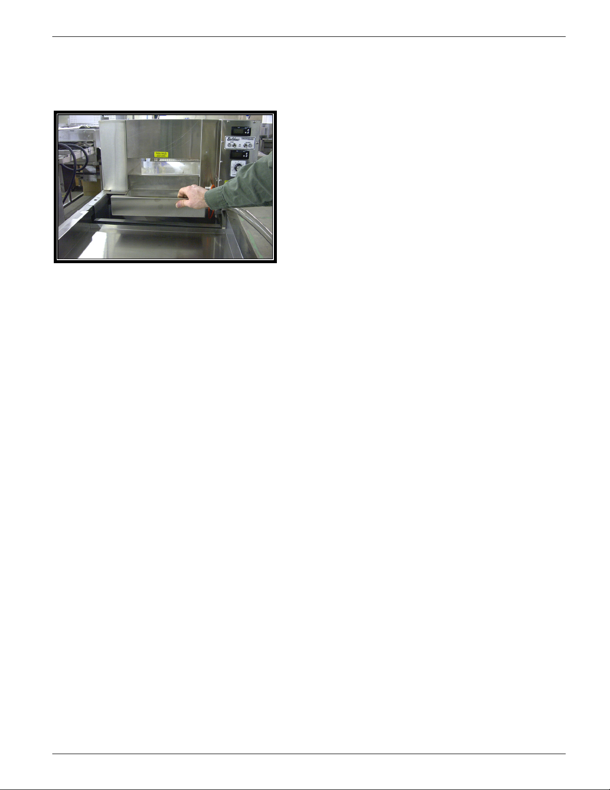
• Lift off water reservoir cover and fill
water reservoir (see Figure 1-1). If
necessary, open the lower door(s) and
remove screen(s) or tray(s) to access the
water reservoir. Do not fill beyond ½” of
the top edge. When finished, replace the
cover and doors. If equipped with the
autofill unit, turn on the water and the
filler unit will stop at the correct water
level.
Note: Do not pull the control box out to gain
access to the water reservoir because water
may be spilled when moving the control box.
• Turn on control box power switch.
• Wait 25 minutes for the Thermolizer to
reach operating temperature.
• After the donuts have been in the
Thermolizer for at least 30 minutes (60
minutes for filled product), turn on glazer
using the on switch located on the main
control panel.
• After the donuts are thawed, place a screen of
CAUTION
If water is spilled while filling the water pan,
thoroughly dry all surfaces including the
floor. Spilled water may cause serious injury,
loss of life, or damage to equipment. Water
may continue to drip. To prevent the floor
from becoming wet and slippery, use a pan to
collect dripping water. Do not move the
Thermolizer when water is in the reservoir.
Note: Use only distilled or purified water in
the Thermolizer to avoid build-up in the
water box of minerals and deposits normally
found in tap water.
Belshaw Bros., Inc. • www.belshaw.com • Phone 206-322-5474 • Fax 206-322-5425
Thermoglaze 25 OM MN-1727EN 1
donuts from Thermolizer box to the infeed
end of the Thermoglaze conveyor and allow
the screen to travel through the oven and
glazer. This takes approximately 2 minutes.
• When the screen of donuts is through the
glazer and stopped forward travel, place the
glazed product on a rack for cooling using
the 2 delrin tray grips provided with the unit.
WARNING
To avoid burning yourself, never touch the
Thermoglaze unit, conveyor, or interior of the
oven while the machine is in use.
Page 8
WARNING
Thoroughly clean and dry the floor if water or
other materials are spilled. Materials spilled
on the floor may cause serious injury and loss
of life.
WARNING
Conveyor will automatically start when
Thermoglaze power switch is turned on.
Water reservoir
cover
CAUTION!
Donut screens are hot after coming out of the
glazer and will burn you if you grab them
without the handles.
Operating the Thermolizer
CAUTION
Do not permit water pan to run out of water.
Check often. Use only soft or distilled water
in the operation of this proofer.
Water Box
access cover
Figure 1-1. Water Reservoir.
Belshaw Bros., Inc. • www.belshaw.com • Phone 206-322-5474 • Fax 206-322-5425
2 MN-1727EN Thermoglaze 25 OM
Page 9
Thermoglaze 25 Symbol Key
Belshaw Bros., Inc. • www.belshaw.com • Phone 206-322-5474 • Fax 206-322-5425
Thermoglaze 25 OM MN-1727EN 3
Page 10
Cleaning 6
Daily TG Cleaning
Instructions
TG 25 Daily Cleaning instructions.
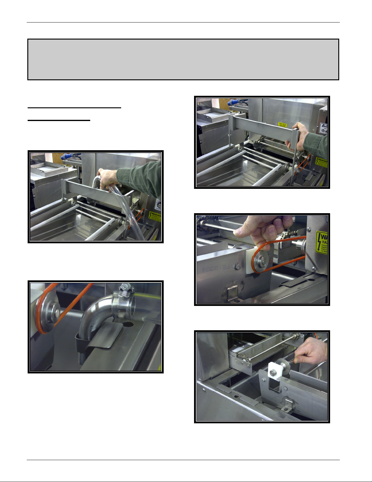
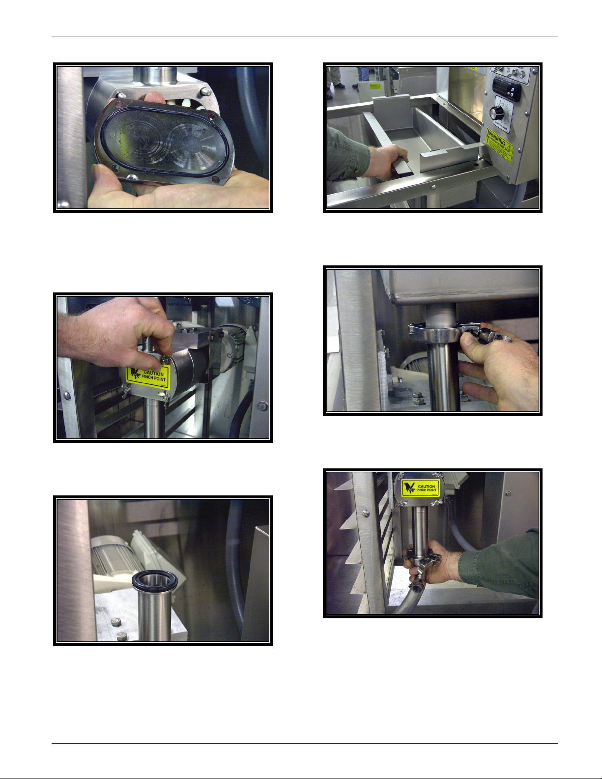
Disassembly:
1. Remove glaze hose from glaze trough
and pump unused glaze into a clean
storage container.
2. Disconnect main power cord.
4. Remove glaze trough.
5. Remove transfer shaft drive belt.
3. Return glaze tube to the holder in the
glaze kettle.
6. Remove the transfer drive shaft.
Belshaw Bros., Inc. • www.belshaw.com • Phone 206-322-5474 • Fax 206-322-5425
4 MN-1727EN Thermoglaze 25 OM
Page 11

7. Remove the drain tray assembly.
8. Remove the outfeed crumb tray.
10. Remove the glaze kettle.
11. Remove the lower hose clamp, hose and
hose gasket.
9. Removed the hose clamp from the glaze
tank drain.
Belshaw Bros., Inc. • www.belshaw.com • Phone 206-322-5474 • Fax 206-322-5425
12. Remove the 4 wing nuts from the glaze
pump cover.
Thermoglaze 25 OM MN-1727EN 5
Page 12
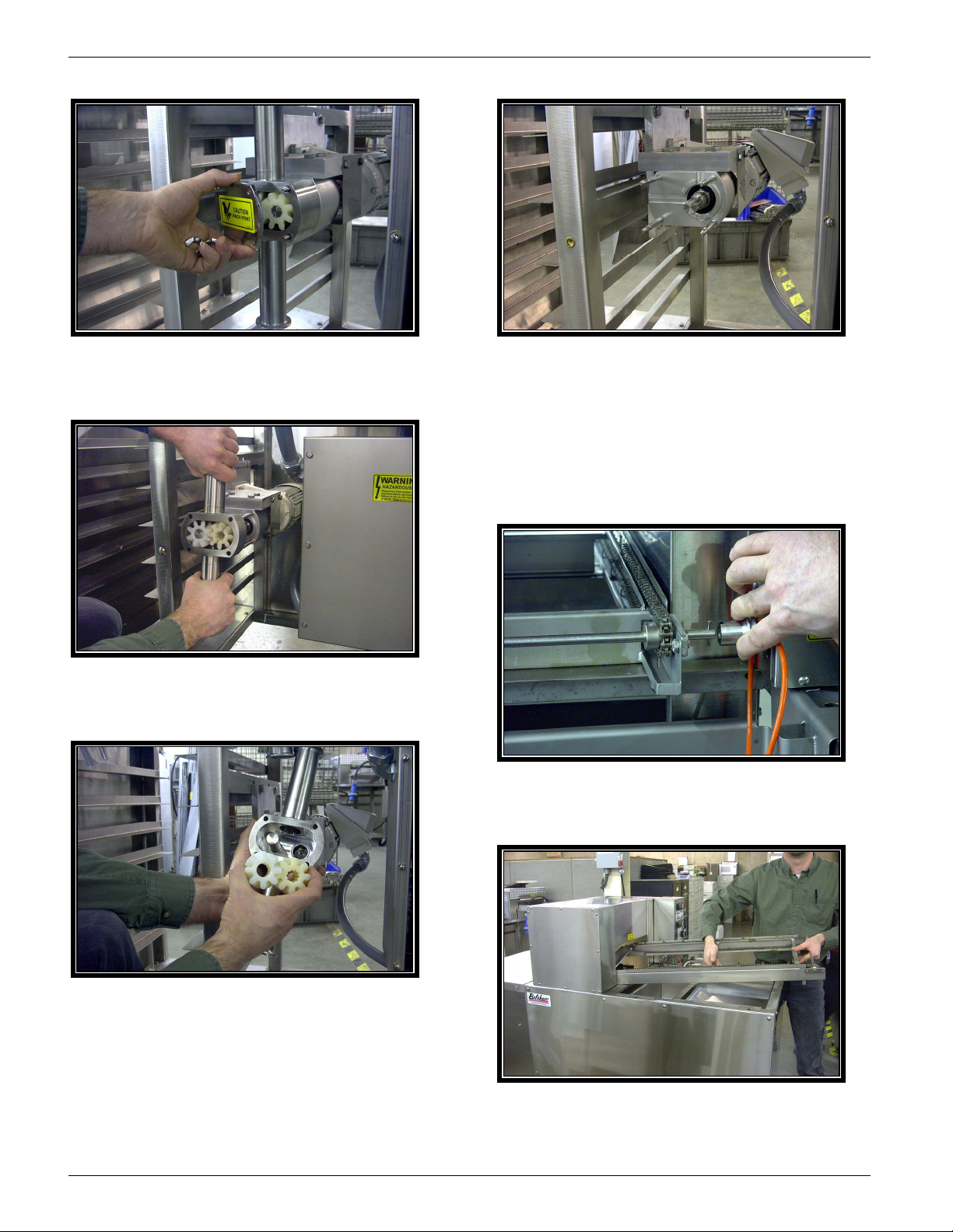
13. Remove the glaze pump cover and
gasket.
14. Remove the pump body and gear
impellers.
16. Clean the pump shaft splines thoroughly
to prevent the gear from sticking onto the
shaft during assembly.
Note: Allow the oven to cool below 130 deg F.
before disassembling the oven or conveyor.
17. Pull the conveyor drive coupling back to
release the conveyor.
15. Remove the gear impellers from the
pump body.
Belshaw Bros., Inc. • www.belshaw.com • Phone 206-322-5474 • Fax 206-322-5425
6 MN-1727EN Thermoglaze 25 OM
Page 13
18. Remove the conveyor assembly trough
the outfeed end of the oven.
19. Remove the oven crumb tray.
20. Hand wash all parts in hot soapy water,
rinse and sanitize.
21. Allow to dry before assembling.
Belshaw Bros., Inc. • www.belshaw.com • Phone 206-322-5474 • Fax 206-322-5425
Thermoglaze 25 OM MN-1727EN 7
Page 14

Assembly:
1. Install the crumb tray.
2. Install the conveyor into the oven and line
up the locating pins at the outfeed end of
the oven.
Note: lubricate the pump shaft “O” ring and
gear impellers with food grade mineral oil
before installation.
3. Install the glaze pump body.
4. Install the drive gear onto the splined
shaft.
CAUTION
Failure to properly clean or lubricate the glaze
pump could cause damage to the pump gear
impellers.
5. Install the lay gear onto the smooth shaft.
Belshaw Bros., Inc. • www.belshaw.com • Phone 206-322-5474 • Fax 206-322-5425
8 MN-1727EN Thermoglaze 25 OM
Page 15
6. Install the glaze pump cover “O” ring into
the cover and install the cover onto the
pump. Make sure the “O” ring stays in
the groove during installation.
7. Install the wing nuts onto the pump, do
not over tighten them.
9. Install the glaze kettle; make sure the
gasket is properly seated.
10. Install the hose clamp. Finger tighten
only, do not use tools.
11. Install the glaze hose, gasket and clamp.
8. Install a hose gasket on the top of the
Finger tighten clamp only.
pump.
Belshaw Bros., Inc. • www.belshaw.com • Phone 206-322-5474 • Fax 206-322-5425
Thermoglaze 25 OM MN-1727EN 9
Page 16
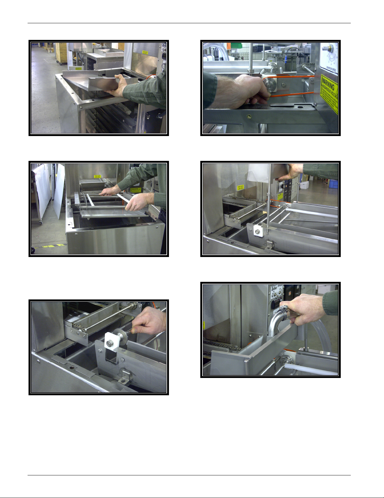
12. Install the outfeed crumb tray.
13. Install the drip tray by lining up the
locating pins at the outfeed end of the
tray.
15. Install the transfer shaft drive belt.
16. Install the glaze trough.
17. Install the glaze hose into the glaze
14. Install the transfer drive shaft assembly.
Belshaw Bros., Inc. • www.belshaw.com • Phone 206-322-5474 • Fax 206-322-5425
trough.
10 MN-1727EN Thermoglaze 25 OM
Page 17

Thermolizer Cleaning
Instructions
Once a week, clean the Thermolizer as follows:
1. Remove and clean Plexiglas doors with
warm water.
2. Disconnect from power and remove control
box from cabinet.
3. Remove and clean the screen rack angles,
angle supports, and air duct.
4. Wipe the cabinet interior clean.
5. Special attention should be given to cleaning
the water box (Item 2 of Control Box Assy.,
parts list drawings). Clean the water box as
follows:
a. Turn off water to the Thermolizer
control box. (Auto-water fill only)
b. Remove water reservoir cover.
c. Empty the water reservoir pan.
d. Remove water box access cover thumb
screw and rotate access cover to open
position. (see Figure 5-1)
e. Use a rubber syringe baster to remove
sediment from the water box. Wipe the
inside of the water box with a rag.
f. Add a small amount of water to the
water reservoir pan. Water should flow
freely into the water box. If not, clean
out the water line between the water box
and the water reservoir pan. Check for
blockage at the water box inlet hole first.
g. Close water box access cover and fasten
with thumbscrew.
h. Replace water reservoir cover.
Belshaw Bros., Inc. • www.belshaw.com • Phone 206-322-5474 • Fax 206-322-5425
Thermoglaze 25 OM MN-1727EN 11
Page 18

Page 19

Thermoglaze
TG 25
Technical Supplement
Belshaw Bros., Inc.
814 44th Street NW, Suite 103
Auburn, WA 98001 USA
Phone: (206) 322-5474 • Fax: (206) 322-5425
Email: service@belshaw.com • http://www.belshaw.com
Page 20

Page 21

Congratulations on buying a new
Thermoglaze from Belshaw Bros., Inc. Please
inspect the unit carefully for damage or
missing pieces immediately after receiving
your system. Belshaw cannot pay for shipping
damage, because the freight company has
accepted the machine from Belshaw in good
condition, and is responsible for its safe delivery.
For your protection, each crate should be
inspected before signing the Bill of Lading to
report any visible damage caused by the
trucker in transit, and account for the number
of crates.
EQUIPMENT RECORD
Please provide the information below when you correspond with us about your machine.
Purchased by _____________________________________________________________________
Installed by ______________________________________________________________________
Date of Installation ________________________________________________________________
Model number ___________________________________________________________________
Serial number
020708
MN-1728EN
Belshaw Bros., Inc.
814 44th Street NW, Suite 103
Auburn, WA 98001
Phone: (206) 322-5474 • Fax: (206) 322-5425
Email: service@belshaw.com • http://www.belshaw.com
Page 22

Page 23

Contents
1 Unloading and Uncrating 1
2 Installation 2
Thermolizer Installation 2
Initial Cleaning 3
3 Assembly 5
Initial Setup Procedure of Thermoglaze Model TG25 7
Initial Setup of Thermolizer 8
4 Maintenance 9
Motor Speed Control Board Adjustment 9
5 Troubleshooting 10
Glazer VFD Status Indicators 10
Troubleshooting the Thermolizer 12
SB-0345 Rev 1 15
SB-0315R3 21
Appendix 27
Parts List Drawing Insert Page Insert
Belshaw Bros., Inc. • www.belshaw.com • Phone 206-322-5474 • Fax 206-322-5425
Thermoglaze 25 TS MN-1728EN iii
Page 24

Preface
The operator of the Thermoglaze is expected to
behave safely, read this manual before operation,
and follow its instructions and warnings.
Study the instructions and warnings in this
manual carefully before operating the equipment.
A thorough understanding of how to install,
maintain, and safely operate the Thermoglaze
will prevent production delays and injuries. Prior
operation of the equipment before reading and
understanding the instructions in the manual will
void the warranties of the equipment.
To use the Thermoglaze safely, heed the
following warnings and all other warnings that
appear in this manual:
• To avoid damaging the Thermoglaze,
never use force to assemble,
disassemble, operate, clean, or maintain
it.
Belshaw Bros., Inc. • www.belshaw.com • Phone 206-322-5474 • Fax 206-322-5425
iv MN-1728EN Thermoglaze 25 TS
Page 25

1 Unloading and Uncrating
DO NOT LIFT EXCESSIVE
WEIGHT
Once the crate has been delivered,
immediately take the covers off the crate and
inspect for hidden damage. If damage is
found, please see the above information to
make a damage claim to the shipping
company. After inspection, cut the banding
and remove any other restraints from the
Thermoglaze unit. Remove the banding and
other packing material from the Thermolizer
unit. Roll the Thermolizer, carefully, off the
skid first and move it near the area where it
will be assembled.
Do not connect the Thermoglaze or the
Thermolizer to electrical power before
completing the assembly and placement of
the products.
The cartons under the Thermoglaze contain the
glaze trough and oven guard. See Section 3 to
assemble the unit. The carton in the Thermolizer
contains the doors and other interior parts. See
Thermolizer manual for assembly instructions.
The Thermoglaze system has been designed for
quick assembly and installation. Within a few
minutes of receiving the system, the installer can
have the Thermoglaze ready to make donuts if
the electrical connections are properly installed
and inspected by the prevailing local authorities.
Belshaw Bros., Inc. • www.belshaw.com • Phone 206-322-5474 • Fax 206-322-5425
Thermoglaze 25 TS MN-1728EN 1
Page 26

2 Installation
Venting:
WARNING
To avoid electrocuting yourself or damaging
the Thermoglaze, never allow water, steam,
cleaning solution, or other liquid to enter the
electrical panels or connections
Electrical:
Model Dimensions Power Requirements
60"L x 31W x
TG25
52"H
See data tag
Local codes prevail. The authorities having
jurisdiction are stated in NFPA 96-1994
regarding requirements for the Thermoglaze.
Building Layouts:
Specification sheets and AutoCAD drawings for
use in developing architectural drawings can be
provided by request. Please call your Belshaw
Bros., Inc. representative for help in defining
your requirements.
Make sure that the power requirements of the
Thermoglaze, shown on the data plate, match
your power source.
Only plug in to power source that matches the
required voltage and current for the
Thermoglaze. (The Thermoglaze unit TG25
comes standard with a Hubbel 360P6W plug that
needs a 360C6W socket or equivalent for
electrical current.
Thermoglaze must be electrically grounded and
connected in compliance with the National
Electrical Code, ANSI-NFPA 70, and applicable
municipal building codes.
Do not apply electrical power to the system until
the assembly has been completed. See Section 4
for the assembly of the Thermoglaze.
WARNING
When handling Thermolizer Control Box,
keep hands and feet clear as injury may occur
if box is dropped.
Thermolizer Installation
Unpacking and Assembling the
Thermolizer
Use a forklift to transport the shipping crate to
the workstation.
1. Break down the shipping crate.
2. Remove the packing materials from the
thermolizer, including foam, tape, brown
paper, plastic, and white protective coating.
Do not remove the plastic from the
Plexiglas doors at this time.
3. Cut the bands holding the control box in
place and remove the control box from the
cabinet.
4. Remove and discard the plywood that the
control box was resting on.
5. Inspect the machine to see that no parts are
bent, scratched, or otherwise damaged. If
any damage has occurred in shipping, file a
freight claim with the shipping company
immediately.
Belshaw Bros., Inc. • www.belshaw.com • Phone 206-322-5474 • Fax 206-322-5425
2 MN-1728EN Thermoglaze 25 TS
6. Clean the humidifier water box and attach to
filtered water per plumbing codes in your
Page 27

area. Refer to Section 2 of the Operator’s
Manual for cleaning instructions. (With
optional auto-water fill only)
WARNING
If water is spilled while cleaning the
thermolizer, be sure to dry the floor
thoroughly.
7. Install screen rack angles onto angle
supports by tilting the angles up and sliding
the flange into the notches of the supports.
See Figure 2-1.
the right of the control panel, and close the
cord opening cover plate.
10. Remove the protective covering from the
Plexiglas doors. Clean the doors with warm
water.
11. Insert the hinge pin on the right side of the
door into place, and then slip the left side
hinge pin into the slot.
WARNING
Pull down and away when opening door on
Thermolizer as not to dislodge door from
hinges. Loose door may cause injury.
Note: due to vibration in shipping, the door
handles might get out of adjustment. To
adjust door handles: loosen the screws which
fasten the handle to the Plexiglas door, adjust
position of the handle so it just clears the
bottom of the door above when both are
closed, and tighten the screws. If more than
one door handle requires adjustment, start
with the one nearest the top of the proofer and
work down.
Figure 2-1
8. If not already done, remove the packing
material from the control box and the put
water reservoir cover in place over the water
reservoir.
9. Place the control box into the cabinet, push
the cord through the hole in the bottom to
12. Turn the control box power switch to the off
position (see Operation Instructions)
13. Connect Thermolizer cord to power source
provided from the ThermoGlaze main power
box.
14. Keep this manual for future reference. Put it
where you know you can find it.
Initial Cleaning
Remove all the packing materials. Wipe the
Thermolizer with a soft, damp cloth. Dry these
areas completely.
Belshaw Bros., Inc. • www.belshaw.com • Phone 206-322-5474 • Fax 206-322-5425
Thermoglaze 25 TS MN-1728EN 3
Page 28

WARNING
To avoid electrocution or other injury, turn off
the machine’s main power before attempting
any cleaning, disassembly, adjustment, or
repair.
Belshaw Bros., Inc. • www.belshaw.com • Phone 206-322-5474 • Fax 206-322-5425
4 MN-1728EN Thermoglaze 25 TS
Page 29

3 Assembly
Clean all parts with mild soap and water and
let dry before assembly and applying
electrical power to the equipment.
The Thermoglaze unit is design for ease of
assembly and use. The system is crated in a
manner so there are few pieces to put together
once the Thermoglaze is in place for production.
To help familiarize you with your Thermoglaze,
please study the following photographs:
Figure 3-1 Front view:
Belshaw Bros., Inc. • www.belshaw.com • Phone 206-322-5474 • Fax 206-322-5425
Thermoglaze 25 TS MN-1728EN 5
Page 30

Figure 3-2 Infeed view.
Figure 3-3 Outfeed View:
Belshaw Bros., Inc. • www.belshaw.com • Phone 206-322-5474 • Fax 206-322-5425
6 MN-1728EN Thermoglaze 25 TS
Page 31

Convection
Heat
Adjustment
Speed
Control
Adjustment
Glaze Speed Adjustment
Figure 3-4. Control Panel View.
The Thermoglaze system consists of a
Thermoglaze unit and the Thermolizer. They are
placed in unison in the area located for the
production of donuts.
Radiant Heat Adjustment
Figure 3-6. Electrical Panel.
Initial Setup Procedure of
Thermoglaze Model TG25
TG-25 Factory Settings
1. Convection Heat: 400°F Digital Controller,
see Figure 3-4
2. Radiant Heat: 6.0 Infinite Controller See
Figure 3-5
3. Conveyor: 7.5 at 90 seconds
4. Glazer: 60% This adjustment needs to be
made according to the thickness of your
glaze. See Figure 3-6
Convection Heat Adjustment
Push the button on the digital controller,
“SP1” will light up. This is the set point. Push
the up and down arrows to adjust the convection
heat set point. See Figure 3-4. Push “R” button
to return to operational mode.
Radiant Heat Adjustment
Disconnect the TG25 from power before
Figure 3-5. Control Box.
Belshaw Bros., Inc. • www.belshaw.com • Phone 206-322-5474 • Fax 206-322-5425
Thermoglaze 25 TS MN-1728EN 7
removing any access covers. This procedure
should be performed only by a qualified service
Page 32

technician. Remove the electrical box cover on
the oven to access the radiant temperature
controller. See Figure 3-5.
Speed Control/Cook Time
Adjustment:
Turn on the oven and allow it to come up to
temperature. This will take about 30 minutes.
Put a glaze screen on the conveyor chains that
run through the oven. With the oven in operation,
time the leading edge of the screen as it enters
the oven until the leading edge just leaves the
exit end of the oven. Turn the converyor speed
adjustment knob until the desired time/speed is
found. To decrease the cook time, turn the knob
clockwise. To increase the cook time, turn the
knob counterclockwise.
Glazer Speed Control
Turn off the power to the TG 25 before opening
electrical control box.
WARNING
Do not operate glazer without glaze or water
in the pump. Doing so can cause permanent
damage to the pump.
Turn the glazer speed control potentiometer
counterclockwise to increase flow of glaze or
clockwise to decrease flow of glaze. See Figure
3-6.
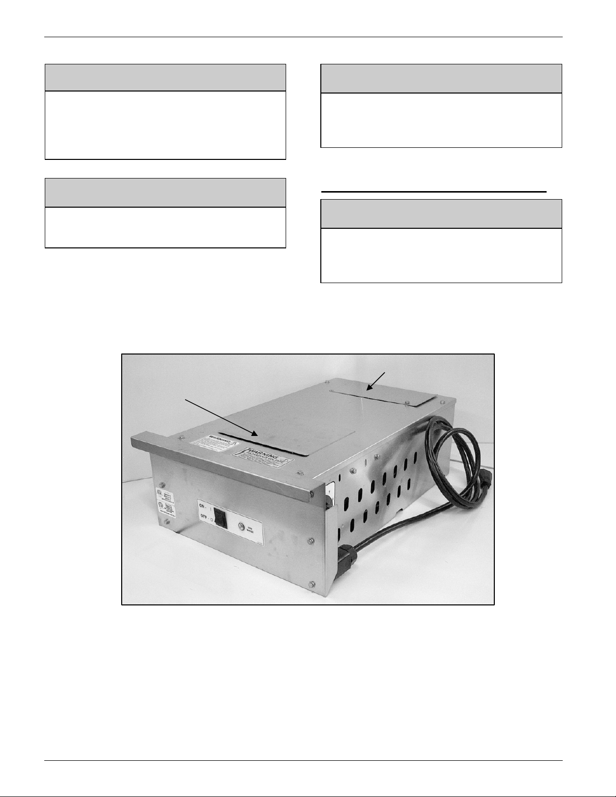
Figure 3-7. Thermolizer Control Box.
Initial Setup of Thermolizer
Humidity Control
This control is located on the left hand side of the
control box behind the front panel. It controls the
water heating element. Set on high, the water
heat element will remain on constantly. Set on
any setting other than high, the control will cycle
on and off. Higher numbered settings create a
longer on-cycle and high humidity. The factory
setting is 5.5 on the dial.
Heat Control
This control is located on the right hand side of
the control box behind the front panel. It controls
the air-heating element. The factory setting is to
place the white dot on the knob at 11:00 to
produce 95° -110°F.
Belshaw Bros., Inc. • www.belshaw.com • Phone 206-322-5474 • Fax 206-322-5425
8 MN-1728EN Thermoglaze 25 TS
Page 33

4 Maintenance
The ThermoGlaze is engineered to need little
maintenance. By keeping the system clean, the
equipment will last for years. The only
maintenance that is required is the following:
When cleaning the donut system, check all
rubber gaskets for wear and replace when
necessary. Check for wear on impellers of the
glaze pump, replace when necessary. .
DO NOT spray machine with water or cleaning
agents to clean. Only wipe main unit off with
damp cloth.
Motor Speed Control Board
Adjustment
1. When installing new motor speed control
board, start by setting the potentiometers as
shown in Figure 4-1.
2. Connect volt meter to “+ arm” and “- arm”
on the board. Set meter to DC Voltage.
3. Turn conveyor speed to maximum
(clockwise).
4. Adjust max pot until the maximum voltage
out is 12 VDC.
Figure 4-1. Motor Speed Pot Adjustment.
Belshaw Bros., Inc. • www.belshaw.com • Phone 206-322-5474 • Fax 206-322-5425
Thermoglaze 25 TS MN-1728EN 9
Page 34

5 Troubleshooting
Call Belshaw Bros. at (206)322-5474, or (800)
578-2547. One of our customer support
representatives will be happy to help you. When
you call, please specify the following:
• The model name of the machine.
• The serial number of the machine.
• The voltage, phase, and hertz (cycle) of
the machine. This information can be
found on the small, rectangular data
tag/plate.
CAUTION
If you perform repairs yourself or have them
performed by anyone other than Belshaw
Bros. or a service technician authorized by
Belshaw Bros., you do so at your own risk.
Following is a troubleshooting chart to help you
identify and solve some basic problems.
WARNING
Disconnect the machine from the power
source before disassembling, repairing, or
wiring.
Glazer VFD Status Indicators
Figure 5-1. KVBF Status Indicators
Belshaw Bros., Inc. • www.belshaw.com • Phone 206-322-5474 • Fax 206-322-5425
10 MN-1728EN Thermoglaze 25 TS
Page 35

CONVEYOR WILL NOT MOVE
Possible Causes What To Do
Conveyor is jammed. Check for obstruction in conveyor and remove.
GLAZER WILL NOT PUMP GLAZE (SEE FIGURE 5-1)
Glazer motor is not running. Check to make sure the motor is running.
(See Pump Motor Will Not Run)
Glazer pump impellers are worn. 1. Disconnect power.
2. Replace impellers.
GLAZE IS MISSING THE DONUTS ON ONE SIDE OF THE GLAZE SCREEN
Glazer or glaze trough is not level. Adjust level of glaze trough by moving set collar.
Glaze pump is running too slow. 1. Disconnect from power.
2. Open Electrical Enclosure.
3. Turn glazer speed control clockwise.
4. Close Electrical Enclosure.
THE PUMP MOTOR WILL NOT RUN
Possible Causes What To Do
The connection of the power cord to the power
source is faulty.
The circuit breaker has been tripped. 1. Disconnect from power.
Make sure the power cord is fully plugged in to a
proper power source.
2. Open electrical enclosure.
3. Reset circuit breaker.
4. Close electrical enclosure.
THE FILL HOSE IS LEAKING
Possible Causes What To Do
Fill hose is leaking at the connection. Hose bracket needs adjusting or tightening.
Fill hose is leaking near the pump. Check for missing or damaged o-ring.
Belshaw Bros., Inc. • www.belshaw.com • Phone 206-322-5474 • Fax 206-322-5425
Thermoglaze 25 TS MN-1728EN 11
Page 36

Troubleshooting the
Thermolizer
If you have problems with your Thermolizer, call
your dealer or another qualified technician.
If your dealer cannot help you, please call
Belshaw. To do so, first dial the appropriate
international access code, then 1-206-322-5474
(United States). When you call, please specify
the following:
• The model name of the machine.
• The serial number of the machine.
• The voltages, phase, and cycle of the
machine.
WARNING
If you perform repairs yourself or have them
performed by anyone other than a service
technician authorized by Belshaw Bros., you
do so at your own risk.
WARNING
Disconnect the machine from the power
source before disassembling, repairing, or
wiring.
Belshaw Bros., Inc. • www.belshaw.com • Phone 206-322-5474 • Fax 206-322-5425
12 MN-1728EN Thermoglaze 25 TS
Page 37

THERMOLIZER WILL NOT TURN ON
Possible Causes What To Do
Power cord is not plugged in Plug power cord into the TG control box
Fuse is blown. Replace the 20 Amp fuse
Circuit breaker is off in the TG control
box.
• Disconnect TG from power.
• Open TG control box.
• Turn on Circuit breaker.
• Close control box.
• Reconnect to power.
THERMOLIZER WILL NOT HEAT UP
Possible Causes What To Do
Control box power switch is not “on.” Flip switch to “on” position.
Defective heat control. Replace the heat control.
Loose wire or bad connection. Repair the wire.
Defective heat element. Replace the heat element.
Defective control box power switch. Replace power switch.
Belshaw Bros., Inc. • www.belshaw.com • Phone 206-322-5474 • Fax 206-322-5425
Thermoglaze 25 TS MN-1728EN 13
Page 38

LACK OF HUMIDITY OR UNEVEN HUMIDITY
Possible Causes What To Do
Low water. Refill water reservoir/Check water is on.
Defective humidity control. Replace the humidity control.
Defective water heat element. Replace the water heat element.
Restriction or sediment in the water line or
the water heat box inlet hole.
Loose wire or bad connection in humidity
circuit.
Blower is not running. See “Blower Will Not Run” section
Doors out of alignment. Align doors.
Clean out water line.
Repair loose wire or connection in
humidity circuit.
BLOWER WILL NOT RUN
Possible Causes What To Do
Control box power switch is not “on.” Flip switch to “on” position.
Defective blower motor. Replace blower motor.
Defective control box power switch. Replace control box power switch.
Loose wire or bad connection in blower
control circuit.
Repair loose wire or bad connection.
Belshaw Bros., Inc. • www.belshaw.com • Phone 206-322-5474 • Fax 206-322-5425
14 MN-1728EN Thermoglaze 25 TS
Page 39

SB-0345 Rev 1
AFFECTS: TG-50
PURPOSE: PROGRAMMING THE OGDEN ETR-9000 TEMPERATURE CONTROLLER
Operator Interface:
The operator interface on the Ogden ETR-9000, Temperature Controller, consists of the following:
• A scroll key
• Up
• A reset key used to return to normal operation mode.
and down arrow keys are used to increase or decrease the selected parameter.
used to select a parameter to be viewed or adjusted.
Figure 1.2 – Operator Interface Description
Menu Overview:
There are three main menus that contain parameters that require programming; they are User Menu,
Setup Menu, and Calibration Mode. The figure below (Figure 2) shows the sequence of operations
necessary to access the programming parameters in each menu.
Belshaw Bros., Inc. • www.belshaw.com • Phone 206-322-5474 • Fax 206-322-5425
Thermoglaze 25 TS MN-1728EN 15
Page 40

Figure 1.3 - Menu Flow Chart
Belshaw Bros., Inc. • www.belshaw.com • Phone 206-322-5474 • Fax 206-322-5425
16 MN-1728EN Thermoglaze 25 TS
Page 41

TG Parameter Settings
Tables 1, 2 and 3 below list of the temperature controller default settings and the Belshaw Factory
settings. When installing a new controller 3 of the default setting must be changed to the Belshaw
Factory settings.
• Push and hold the scroll key
• Push the scroll key
• Push the Up
• Push the scroll key
change the settings listed in the Belshaw “Factory” column. (see tables 1, 2 and 3)
When finished setting parameters.
• Continue pushing the scroll key
• Push the Up
• Push the reset key
or down arrow keys to change “LocK” to “nonE”.
or down arrow keys to set “LocK” to “uSEr”.
once to access the “LocK” parameter.
to page through the settings and the Up or down arrow keys to
to return normal operation.
for 3 seconds, this will take you to the “SEt” menu.
until you are back to “LocK”.
Default Settings:
In the event that parameters have been modified without recording the modifications, change each
parameter to match those listed in Tables 1, 2 and 3 listed below (controller parameter default settings).
Then adjust SP1H, PB, OUT2 and the LocK parameters as listed in Belshaw “Factory” below. Then set
SP1 to 420ºF.
Belshaw Bros., Inc. • www.belshaw.com • Phone 206-322-5474 • Fax 206-322-5425
Thermoglaze 25 TS MN-1728EN 17
Page 42

Table 1 - Parameter Descriptions
Factory
420ºF
set to
“uSEr”
after
setup
450ºF
-40ºF
0ºF
0ºF
Belshaw Bros., Inc. • www.belshaw.com • Phone 206-322-5474 • Fax 206-322-5425
18 MN-1728EN Thermoglaze 25 TS
Page 43

Table 2 - Parameter Descriptions
Set to
“nonE”
Belshaw Bros., Inc. • www.belshaw.com • Phone 206-322-5474 • Fax 206-322-5425
Thermoglaze 25 TS MN-1728EN 19
Page 44

Table 3 - Parameter Descriptions
Set to
Belshaw Bros., Inc. • www.belshaw.com • Phone 206-322-5474 • Fax 206-322-5425
20 MN-1728EN Thermoglaze 25 TS
Page 45

SB-0315R3
AFFECTS: TG-50, TG-25 REVISED: 5/10/2006 JD
PURPOSE: VFD-0017-3 PROGRAMMING INSTRUCTIONS
DISPLAY
ENTER BUTTON
Figure 1
ESC
SCROLL UP/SCROLL
DOWN
Figure 2
Belshaw Bros., Inc. • www.belshaw.com • Phone 206-322-5474 • Fax 206-322-5425
Thermoglaze 25 TS MN-1728EN 21
Page 46

General:
Figure 1, above, shows the location of programming/navigating buttons on the face of the Altivar 11
(Belshaw P/N: VFD-0017). Figure 2 shows the navigation paths to various programming parameters.
The following has been adapted from the ATV11 Technical Manual which can be found at
http://ecatalog.squared.com/pubs/Motor%20Control/AC%20Drives/Altivar%2011/VVDED302026US.pdf
Programming:
Using Figures 1, and 2 navigate to the following programming parameters and set them as shown below
in Table 1. Items listed as default are set at the factory and should be verified.
The parameters in unshaded boxes can only be modified when the controller is stopped.
Remove jumper wire from terminal 15 to stop drive.
The parameters in shaded boxes can be modified with the controller operating or stopped.
MENU PARAMETER SECONDARY
1st Level ACC Acceleration ramp time
dEC Deceleration ramp time
LSP Low Speed (hz) 0 (default)
HSP High Speed (hz) 50/60 (default) based on motor
ItH Motor thermal current
Alt Configuration of Analog
drC UnS Motor voltage (volts) 230
FrS Motor frequency (hz) 60
nCr Motor current (amps) 2.1
COS Motor power factor .80
FUn tCC ACt 2-wire control 2c (default)
tCt Type of 2-wire control LEL
rrS Reverse operation nO
PS2 L1A Assignment of L1A nO
L1b Assignment of L1B nO
PI PIF Assignment of PI
rSF Fault reset nO (default)
bFr Motor Frequency (hz) 60 for domestic machines
FUNCTION SETTING
PARAMETER
3 (default)
(sec.)
3 (default)
(sec.)
Hz
2.1
(amps)
Input
function feedback
(Set to motor nameplate amps)
5U (default)
(Set to motor nameplate
voltage)
(Set to motor nameplate
frequency)
(Set to motor nameplate
current)
(Set to motor nameplate power
factor (sometimes labeled ‘pf’))
nO (default)
(default).
50 for AS/NZ, and CE
machines;
Belshaw Bros., Inc. • www.belshaw.com • Phone 206-322-5474 • Fax 206-322-5425
22 MN-1728EN Thermoglaze 25 TS
Page 47

Returning VFD to factory default settings:
Sometimes the easiest way to ensure that the VFD has the correct operating parameters is to
return the configuration parameters to factory default and re-enter the few parameters changed
for use with the TG-25 and the TG-50s. There are currently over 50 adjustable parameters
available with this VFD of which 11 need to be changed from factory default
To reset the VFD to operate on the TGs, reset the parameters to the factory default as shown
below and re-enter and/or verify the parameters in the programming section above.
MENU PARAMETER SECONDARY
PARAMETER
FUn FCS Reset
FUNCTION SETTING
Lnl (Must hold ENT
configuration to
factory default
key for 2 sec)
ONLY USE THIS
PARAMETER TO
RETURN VFD TO
FACTOR DEFAULT
CONFIGURATION.
IF
Note The drive must be stopped to modify this parameter. Remove jumper wire from terminal 15 to
stop drive
FAULTS – CAUSES – REMEDIES
Clearing the fault:
Cut the power supply to the drive in the event of a non-resettable fault.
Wait for the display to go off completely.
Find the cause of the fault in order to correct it.
Restore the power supply – this clears the fault if it has disappeared.
Drive does not start, no fault displayed:
Check that the run command input has been jumpered (Jumper is required between terminals
LI1 and +15V).
When the drive is switched on, or at a manual fault reset, or after a stop command, the motor
can only be supplied with power once the ”forward” commands have been reset. Otherwise, the
drive will display “rdy” or “nSt” but will not start.
Belshaw Bros., Inc. • www.belshaw.com • Phone 206-322-5474 • Fax 206-322-5425
Thermoglaze 25 TS MN-1728EN 23
Page 48

Drive does not start, display off:
Check that line voltage is present at the drive terminals
Unplug all the connections on the drive U, V, W terminals and check that there is no short circuit
between the phase and earth in the motor wiring or in the motor.
Faults which cannot be reset automatically:
The cause of the fault must be removed before resetting by switching power off and on again.
FAULT PROBABLE CAUSE REMEDY
CFF
Configuration fault
CrF
Capacitor charging
circuit
InF
Internal fault
OCF
Overcurrent
SCF
Motor short-circuit
SOF
Overspeed
• The current
configuration is
inconsistent
• Load relay control fault
or charging resistor
damaged
• Internal fault • Check the environment
• Ramp to short
• Inertia or load too high
• Mechanical locking
• Insulation fault or short-
circuit at the drive
output
• Instability or driving load
too high
• Return to factory settings and re-enter
parameters
• Replace the drive
(electromagnetic compatibility)
• Replace drive
• Check the settings
• Check the size of the motor/drive/load
• Check the state of the mechanism
• Check the cables connecting the drive
to the motor, and the motor insulation
• Check the motor, gain and stability
parameters
• Add a breaking resistor and module
• Check the size of the motor/drive/load
Belshaw Bros., Inc. • www.belshaw.com • Phone 206-322-5474 • Fax 206-322-5425
24 MN-1728EN Thermoglaze 25 TS
Page 49

Faults which can be reset with automatic restart function, after the cause of the fault disappeared:
These faults can also be reset by switching the drive off and on again.
FAULT PROBABLE CAUSE REMEDY
ObF
Overvoltage during
deceleration
OHF
Drive over
temperature
OLF
Motor overload
OSF
Overvoltage
PHF
Line phase failure
• Braking too sudden or
driving load
• Drive temperature too
high
• Trigger by motor current
too high
• Line voltage too high
• Disturbed line supply
• Dive incorrectly
supplied of blown circuit
protection
• Failure of one phase
• Increase the deceleration time
• Install a braking module and a braking
• Activate the brA function if it is
• Sheck the motor load, the drive
• Check the setting of the motor thermal
• Check the line voltage. The
• Check the power connections and the
• Reset
Faults which can be reset as soon as its cause disappears:
resistor if necessary
compatible with the application
ventilation and the environment. Wait
for the drive to cool down before
restarting
protection, check the motor load. Wait
for the motor to cool down before
restarting
overvoltage threshold is 415VDC on
the DC bus
circuit protection
FAULT PROBABLE CAUSE REMEDY
USF
Undervoltage
• Line supply too low
• Transient voltage dip
• Damaged load resistor
• Check the voltage and the voltage
parameter. The undervoltage
threshold is 230vDC on the DC bus
• Replace the drive
Belshaw Bros., Inc. • www.belshaw.com • Phone 206-322-5474 • Fax 206-322-5425
Thermoglaze 25 TS MN-1728EN 25
Page 50

Page 51

6 Appendix
See Parts List Drawing Insert Page.
Belshaw Bros., Inc. • www.belshaw.com • Phone 206-322-5474 • Fax 206-322-5425
Thermoglaze 25 TS MN-1728EN 27
 Loading...