

Page 1

Belshaw Bros., Inc • 814 44th Street NW, Suite 103 • Auburn, WA 98001 • USA
Tel: 206-322-5474 • Fax: 206-322-5425 • www.belshaw.com
INFORMATION FOR CUSTOMERS
AND APPROVAL AUTHORITIES
INSIDER
DONUT FRYING SYSTEM
COMMERCIAL ELECTRIC COOKING APPLIANCE
WITH INTEGRAL RECIRCULATING SYSTEM
INSTALLATION REQUIREMENTS
• INSIDER FLYER
• SPECIFICATION SHEET
• FIRE SUPPRESSION DESCRIPTION
• INSTALLATION INFORMATION
• STANDARDS & LISTINGS – ETL/UL/NFPA
• ETL/UL LABELS
• PYRO-CHEM DATA SHEET
COMPLETE INSTALLATION PROCEDURES ARE LISTED IN THE
INSIDER INSTALLATION, OPERATORS AND MAINTENANCE MANUAL
Page 2

Page 3

Belshaw Bros., Inc • 814 44th Street NW, Suite 103 • Auburn, WA 98001 • USA
Tel: 206-322-5474 • Fax: 206-322-5425 • www.belshaw.com
Insider™
The Belshaw’s Insider™ (Donut Frying System) comprehensively addresses all fire
prevention, clean air, sanitation and electrical requirements and the self-contained unit
meets or exceeds local standards. The Insider houses one of the following Donut Robot
Fryers; MKII, MKV or MKIX and is UL197 Listed under ETL #68183.
• Tested to UL197 standards for Commercial Electric Cooking Appliances with
Recirculating Systems and Listed under ETL #68183.
• Intended for installation and use to NFPA-96 Standard For Ventilation Control
and Fire Protection of Commercial Cooking Operations.
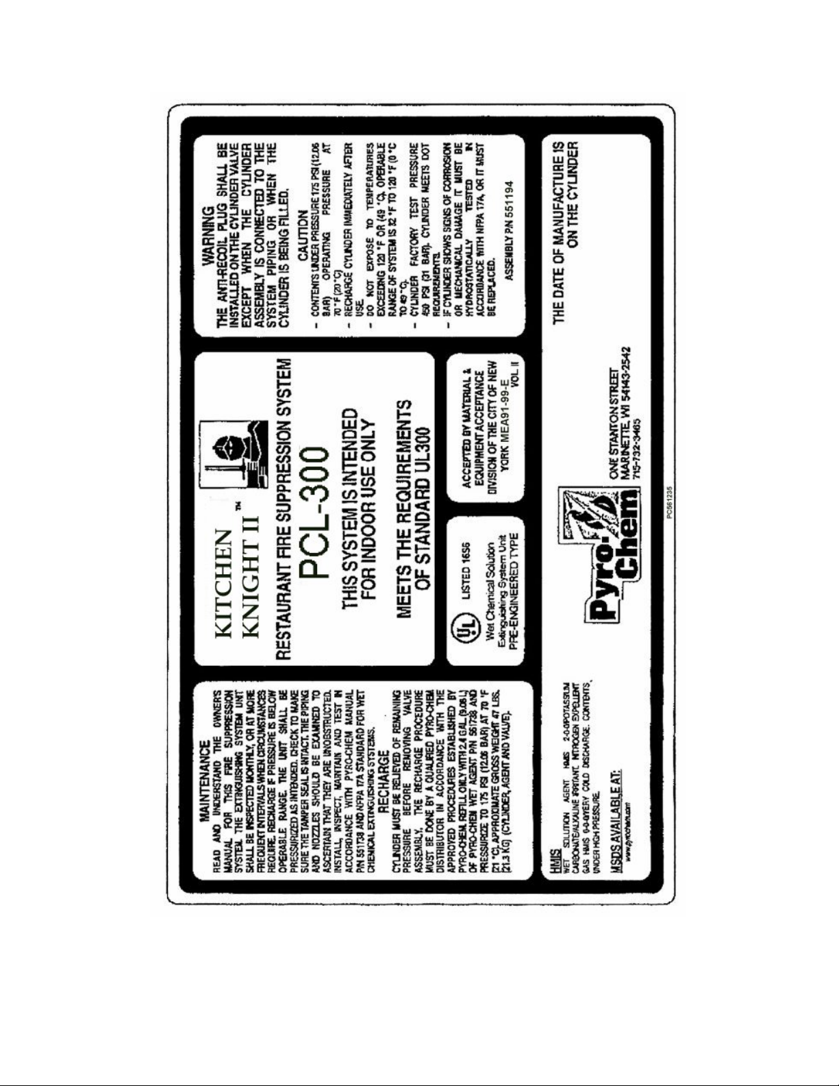
Fire Prevention/ Suppression System
The Insider™ uses the Pyro-Chem Restaurant Fire Suppression System. It is a preengineered type as defined by NFPA-17A Standard for Wet Chemical Extinguishing
Systems and is designed to provide fire protection for restaurant cooking appliances,
hoods, and ducts.
The Pyro-Chem System (PLC-240/300 KITCHEN KNIGHT II) utilizes a wet chemical
agent specifically designed to suppress restaurant-cooking fires. The system
provides automatic actuation and can be manually actuated through a remote
mechanical pull station. Upon actuation, the system discharges a pre-determined
amount of agent to the duct, plenum, and cooking appliances. The agent acts to
suppress fires in 3 ways:
• Both the agent itself and the resulting steam formation interrupt the chemical
chain reaction causing combustion.
• The agent cools the fire bringing it below auto-ignition temperature.
• The agent reacts with hot grease forming a soap-like layer (saponification)
that helps prevent the escape of combustible vapors, thus preventing reignition.
The Pyro-Chem Restaurant Fire Suppression System has been tested to the UL
Standard for Fire Extinguishing Systems For Protection of Restaurant Cooking
Areas, UL300 and Pyro-Chem listed by Underwriters Laboratories, Inc. under
ULC/ORD-C1254.6-1995 listing meets Underwriters Laboratories of Canada’s
standards.
Page 4

Clean Air- Ozone and Emissions
The Insider™ meets the emission requirements of 5.0mg/m3 as measured at the
exhaust outlet of the system per the requirements of the U.S. Environmental Protection
Agency (EPA) Test Method 202, Determination of Condensable Particulate Emissions
from Stationary Sources, which is referenced in NFPA-96 (Test results 1.81 mg/m3) UL
File E213302.
Underwriters Laboratories also tested it at well below the maximum ozone levels
permitted of 0.1ppm time-weighted average with a maximum peak concentration of
0.3ppm (Test results less than 0.015 ppm).
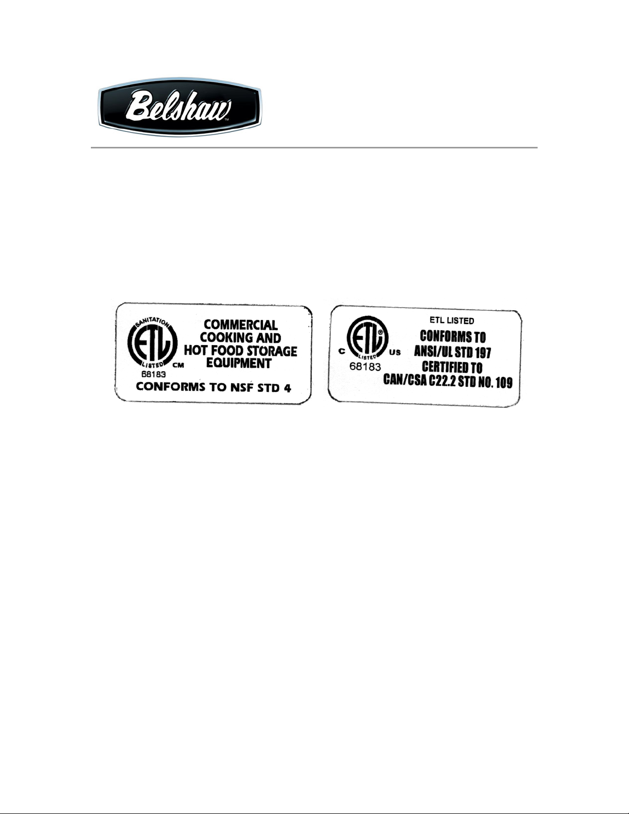
Sanitation
The Insider™ is built in accordance with NSF International Standard No. 4, for
commercial cooking and hot food storage equipment and conforms to ANSI/NSF STD 4
(ETL Listing #68183).
The fryer portion, Donut Robot Mark II, Mark V, or the Mark IX, is separately ETL
Classified in accordance with NSF International Standard No. 4. One of the above
models is used in each Insider™:
Materials employed have been found to be able to withstand normal wear, penetration of
vermin, corrosive action of foods, cleaning products, and other elements in the end use
environment. The materials do not impart an odor, color, taste, or toxic material to food
products.
Electrical
The Insider™ and the Mark Donut Robots are also listed as Commercial Cooking
Appliances, in accordance with UL 197, and they are in compliance with electrical code
ANSI/NFPA 70 the Standard for Commercial Electric Cooking Appliances and conforms
to ANSI/UL STD 197 Certified to CAN/CSA C22.2 STD No. 109 (ETL Listing #68183).
Page 5

Belshaw Bros., Inc • 814 44th Street NW, Suite 103 • Auburn, WA 98001 • USA
Tel: 206-322-5474 • Fax: 206-322-5425 • www.belshaw.com
Insider Installation Requirements
INSTALLATION must be done by certified personnel acceptable to the authority
having jurisdiction and they shall inspect and test the Insider. A test of the safety
interlocks, control head and manual pull station may be performed and a trip test and
dry pressure test may also be required at installation.
The charging and setup of the Pyro-Chem PLC-240/300 Fire Suppression System must
be done by certified personnel and the use and maintenance of the Insider is to be in
accordance with NFPA-96.
The manufacturer’s instructions for “System Checkout after Installation” is on page 17
of the Insider Installation, Operators and Maintenance Manual.
After testing, the Fire Suppression System will need to be activated by screwing the
carbon dioxide pilot cartridge into the actuator, removing the control head safety pull pin,
replacing the control head cover and removing the Fire Damper Safety Pin.
A signed and dated log of installation and maintenance must be kept on premises for use
by authority having jurisdiction.
ETL/UL/NFPA - STANDARDS AND LISTINGS
• UL197SB/UL710B (KNKG7) - Standard for Commercial Electrical Cooking
Appliances with Integral Recirculating Systems and Listed under ETL #68183,
Conforms to ANSI/UL STD 197, certified to CAN/CSA C22.2 STD No. 109
• NSF 4 –Commercial Cooking, Rethermalization and Powered Hot Food Holding
and Transport Equipment and Listed under ETL #68183, conforms to
ANSI/NSF4-2002e.
• NFPA-96 - used in accordance with Standard For Ventilation Control and Fire
Protection of Commercial Cooking Operations.
• NFPA-17A - the Insider uses the pre-engineered Pyro-Chem Restaurant Fire
Suppression System (PLC-240/300 Kitchen Knight II).
Page 6

ETL/UL/NFPA cont.
• UL300 - Standard For Fire Extinguishing Systems For Protection of Restaurant
Cooking Areas and Pyro-Chem Listed under ULC/ORD-C1254.6-1995.
• ANSI/NFPA 70 - Electrical Code – used in accordance with Standard for
Commercial Electric Cooking Appliances.
LOCAL PERMITS and approval by the Fire Marshal may be required. The Insider is a
UL Listed portable plug in appliance (single) and is not a fixture. It is a portable
appliance for use in noncombustible surroundings.
MODIFICATIONS AND CHANGES will invalidate the ETL Listing of this appliance.
The Insider has been fire tested by UL/ETL, as a stand-alone appliance, and is not subject
to change. The ETL Listing does not allow it to be hardwired or permanently attached to
the building structure. The Remote Manual Pull Station must remain on the Insider as
UL/ETL Listed and Tested. The Fire Suppression System shuts down all electrical
circuits during a fire. An auxiliary circuit or permanent connection to the building alarm
system is not a part of this ETL Listing.
Page 7
Belshaw Bros., Inc • 814 44th Street NW, Suite 103 • Auburn, WA 98001 • USA
Tel: 206-322-5474 • Fax: 206-322-5425 • www.belshaw.com
Insider Certification Labels
Page 8
Page 9

Insider
With Air Filtration Hood and Fire
Extinguishing System
Operator's Manual
Belshaw Bros., Inc.
814 44th Street NW, Suite 103
Auburn, WA 98001 USA
Phone: (206) 322-5474 • Fax: (206) 322-5425
E-mail: service@belshaw.com • http://www.belshaw.com
Page 10

Page 11

If you accept the machine from the shipping
company, you are, in effect, saying that the
machine is in good condition, and you must
pay for the machine. Belshaw cannot pay for
shipping damage, because the freight company
has accepted the machine from Belshaw in good
condition, and is responsible for its safe delivery.
For your protection, inspect the machine to see
that no parts are bent, scratched, or otherwise
damaged. If any damage has occurred in
shipping, file a freight claim with the shipping
company immediately.
EQUIPMENT RECORD
Please provide the information below when you correspond with us about your machine.
Purchased by _____________________________________________________________________
Installed by ______________________________________________________________________
Date of Installation ________________________________________________________________
Model number ___________________________________________________________________
Serial number
021208
MN-1852EN
Belshaw Bros., Inc.
814 44th Street NW, Suite 103
Auburn, WA 98001 USA
Phone: (206) 322-5474 • Fax: (206) 322-5425
E-mail: service@belshaw.com • http://www.belshaw.com
Page 12

Page 13

Contents
1 Operation 1
Startup/Run 1
Shutdown 1
In Case of Fire 2
2 Cleaning 3
Cleaning 3
Hand Washing Instructions 4
Automatic Dishwasher Instructions 4
Cleaning Windows & Sliding Doors 5
Belshaw Bros., Inc. • www.belshaw.com • Phone 206-322-5474 • Fax 206-322-5425
Insider OM MN-1852EN iii
Page 14

Preface
The Insider is designed to hold and power the
Belshaw Mark II, V, or IX Fryer and is provided
with an air filtration and fire extinguishing
system. It is not designed for any other purpose.
The operator must work safely at all times, read
included manuals, and follow all instructions and
warnings. A thorough understanding of how to
install, maintain, and safely operate the Insider
will prevent production delays and injuries.
To use the Insider safely, heed the following
warnings and all other warnings that appear in
this manual:
WARNING
THE CHARGING & SETUP OF THE PYRO-
CHEM PLC-240/300 FIRE SUPPRESSION
SYSTEM MUST BE DONE BY CERTIFIED
PERSONNEL ON A REGULAR BASIS
AND THE USE AND MAINTAINENCE OF
THE INSIDER IS TO BE IN ACCORDANCE
WITH NFPA-96.
• Be careful never to get shortening, water,
or other materials on the floor. If
anything does get spilled on the floor,
mop it up immediately. Materials on the
floor can cause people to slip or fall,
resulting in serious injury or loss of life.
• To prevent unintentional startup and
possible fire, unplug the machine if there
is a local power outage. When the
power is restored, it is safe to plug the
machine in again.
• To avoid electrocution, make sure that
all electrical cords are not frayed or
cracked and that they do not pass
through any water or shortening.
• Make sure that all electrical cords are
routed so that no one will trip over them.
• The Insider is “Intended for use in
noncombustible surroundings only.”
• To avoid damaging the machine, never
use force to assemble, disassemble,
operate, clean, or maintain it.
Belshaw Bros., Inc. • www.belshaw.com • Phone 206-322-5474 • Fax 206-322-5425
iv MN-1852EN Insider OM
Page 15

1 Operation
Startup/Run
1. Make sure all filters are properly installed
and all doors are closed.
2. Check the fire suppression cylinder gauge
for the proper range of pressure and the red
control box indicator for the set mode.
CAUTION
Do not operate the Insider if gauge
pressure is low or set mode is not
displayed. The fire suppression system
will not operate.
3. Plug the Mark II, V, or IX Fryer power cord
into the receptacle labeled “Fryer” on the
electrical box. The large hole in the counter
top is for the power cord of the fryer.
CAUTION
Do not operate the Insider with
polycarbonate windows or doors
removed or open. Fire suppression
system will cause hot shortening to
splatter causing serious injury and
burns.
4. Turn on the fryer, Insider and auxiliary
circuit breakers.
II, V, or IX Fryer manual for information on
fryer and cutter operation).
8. After charging and setup by certified
personnel, the fire suppression system is
always operational.
9. Note: If manual operation of the fire
suppression system is required, the system
can be actuated by pulling the handle
straight out. The manual actuator is located
to the right of the red fire suppression
cylinder.
Shutdown
1. Pushing the "Stop" button shuts off all
power to the unit, including fryer.
2. Opening the hood doors, removing a filter or
operation of the fire suppression system will
shutdown the Insider.
3. The unit will not restart if the fire
suppression system has been operated.
Recharging and setup by certified personnel
will be required.
4. After shutdown disconnect power and let
shortening cool to 100° F/38° C before
disassembling or cleaning fryer. Refer to
Mark II, V, or IX manual for instructions.
WARNING
5. Plug the Insider main power plug into the
customer supplied power receptacle.
6. Push the green "Start" button to energize the
unit. Hold the “Start” button in for a few
seconds while the proper airflow is attained.
7. The system must be on to provide power to
the air filtration system, overhead lights,
auxiliary outlet, fryer and cutter. (See Mark
Belshaw Bros., Inc. • www.belshaw.com • Phone 206-322-5474 • Fax 206-322-5425
Insider OM MN-1852EN 1
Electrical Shock Hazard. Have power off
and disconnected at source before doing
any cleaning or maintenance.
Page 16

In Case of Fire
Fires can potentially start in the fryer, the hood,
or the duct. In case of fire, it is important that
you fully understand the operation of your fire
suppression system.
1. Evacuate all personnel and customers from
the fire area.
2. If your fire suppression system has not
already automatically activated, you may
activate it manually by pulling the handle on
the silver manual pull station, located at the
back of the Insider to the right of the red fire
suppression cylinder.
3. Call the Fire Department.
4. Personnel trained in the proper operation of
hand portable extinguishers may stand by if
means of easy exit are available.
When the fire has been extinguished, call your
local authorized Pyro-Chem distributor to
recharge the system, after determining the cause
of fire. Under no circumstances should cooking
operations be attempted before qualified
personnel re-instate the integrity of your fire
suppression system.
Belshaw Bros., Inc. • www.belshaw.com • Phone 206-322-5474 • Fax 206-322-5425
2 MN-1852EN Insider OM
Page 17

2 Cleaning
Cleaning
WARNING
Thoroughly clean and dry floor if
shortening, water, or other materials are
spilled. If spillage is not cleaned and
dried there will be danger of serious
injury or loss of life.
WARNING
Do not use flammable solvents or other
flammable cleaning aids for cleaning.
WARNING
Do not apply cleaning chemicals on
fusible links or other detection devices of
the automatic fire suppression system.
Hood, cabinet, counter top, fans, ducts, and other
surfaces should be cleaned to bare metal at
frequent intervals or a minimum of every 3
months, before they become heavily
contaminated with grease or oily sludge. They
should be inspected at least once every month.
If a vent cleaning service is used, a certificate
showing date of inspection or cleaning should be
maintained on the premises.
A certified person acceptable to the authority
having jurisdiction shall inspect the entire
system.
IMPORTANT
A signed and dated log of maintenance
must be kept on premises for use by
authority having jurisdiction.
WARNING
Handle the air cleaner cell carefully to
avoid damage.
The pre-filter, and grease filter should be
cleaned daily. The air cleaner cell should be
washed weekly. The doors on the hood
provide access to the air cleaner cell and prefilter (see Illustration A).
Replacement filters
Qty. Part No. Description
1 H200-002 Primary Grease Filter
1 I-0123 Pre-Filter
1 IN-0526 Air Cleaner Cell
1 I-0181 Air Baffle
2 I-0068 Carbon Filter
Belshaw Bros., Inc. • www.belshaw.com • Phone 206-322-5474 • Fax 206-322-5425
Insider OM MN-1852EN 3
Page 18

Illustration A
Note: See section 3, on page 20 for air
cleaner cell maintenance and washing
instructions.
until the water draining from the cell, prefilter and grease filter no longer feels
slippery.
Automatic Dishwasher
Instructions
1. Put the air cleaner cell on the lower rack of
the dishwasher with the airflow arrow
pointing up. It maybe necessary to remove
the upper rack. Don't block water flow to
the upper arm, if provided on your
dishwasher.
2. If you are washing the pre-filter and grease
filter with the cell, place them where they
won't block the water from the electronic
cell.
Hand Washing Instructions
Note: Always wash the air cleaner cell first,
then the pre-filters. This will help keep heavy
lint on the pre-filter from getting caught in the
cells.
Wash the cell and filters as follows:
1. Use a container large enough to hold the air
cleaner cell, such as a laundry tub or trash
container.
2. Dissolve about 3/4 cup of automatic
dishwasher detergent in enough hot water to
cover the cell. If the detergent doesn't
dissolve readily, or forms a scum on the
water, try another brand, or use softened
water.
3. After the detergent has completely
dissolved, place the cell in the container and
let soak for 15-20 minutes. Agitate up and
down a few times, and remove.
4. Next, wash the pre-filter and grease filter the
same way. Empty and rinse the wash
container.
5. Rinse the cell, pre-filters and grease filter
with a hard spray of very hot water, rinse the
tub clean, and then fill the tub with clean hot
water and soak for 5 to 15 minutes. Rinse
3. Using the detergent that works best for
normal dishwashing, allow the dishwasher to
run through the complete wash and rinse
cycle. Do not use the dry cycle. To avoid
burns, wear protective gloves when
removing the cell, or let it cool first.
Remember that water maybe trapped in the
tubes supporting the collector plates. Tip the
cell so these tubes can drain.
4. Inspect the dishwasher. You may wish to
rerun the wash and/ or rinse cycle with the
dishwasher empty if you see dirt or residue
from washing the cell. If dirt or residue
seems excessive, wash the cell more often or
try a different detergent.
WARNING
Allow the cell to cool or wear protective
gloves to avoid burns. Hot water may
accumulate in the tubes supporting the
collector plates. Tip the cells so these
tubes will drain.
5. Wipe the ionizer wires and red contact board
with a clean cloth.
6. Reinstall the filters and air cleaner cell.
Note: A snapping sound may be heard when the
cell is reinstalled after washing. This is caused
Belshaw Bros., Inc. • 1750 22nd Ave. S. • Seattle, WA 98144 • Phone 206-322-5474 • Fax 206-322-5425
4 MN-1852EN Insider
Page 19

by arcing do to water remaining in the cell. This
will cause no harm and the sound will quit when
the cell has dried
Cleaning Windows &
Sliding Doors
1. Use a mild liquid dishwashing soap and a
soft cloth or sponge.
2. Dry with soft cloth.
WARNING
Polycarbonate will mark easily, be very
careful while handling. DO NOT use any
solvents or cleaning chemicals
Belshaw Bros., Inc. • www.belshaw.com • Phone 206-322-5474 • Fax 206-322-5425
Insider OM MN-1852EN 5
Page 20

Page 21

Insider
With Air Filtration Hood and Fire
Extinguishing System
Technical Supplement
Belshaw Bros., Inc.
814 44th Street NW, Suite 103
Auburn, WA 98001 USA
Phone: (206) 322-5474 • Fax: (206) 322-5425
E-mail: service@belshaw.com • http://www.belshaw.com
Page 22

Page 23

If you accept the machine from the shipping
company, you are, in effect, saying that the
machine is in good condition, and you must
pay for the machine. Belshaw cannot pay for
shipping damage, because the freight company
has accepted the machine from Belshaw in good
condition, and is responsible for its safe delivery.
For your protection, inspect the machine to see
that no parts are bent, scratched, or otherwise
damaged. If any damage has occurred in
To unpack the Insider and transport it to the
workstation:
1. Use a forklift or a pallet jack to move the
shipping crate to the workstation.
2. Remove the machine from the shipping
crate, being careful not to lose or damage
any of the parts.
3. Remove all packing materials from the
machine.
shipping, file a freight claim with the shipping
company immediately.
EQUIPMENT RECORD
Please provide the information below when you correspond with us about your machine.
Purchased by _____________________________________________________________________
Installed by ______________________________________________________________________
Date of Installation ________________________________________________________________
Model number ___________________________________________________________________
Serial number
021208
MN-1853EN
Belshaw Bros., Inc.
814 44th Street NW, Suite 103
Auburn, WA 98001 USA
Phone: (206) 322-5474 • Fax: (206) 322-5425
E-mail: service@belshaw.com • http://www.belshaw.com
Page 24

Page 25

Contents
1 Installation 1
Unpacking the Insider 1
Initial Cleaning 1
Replacement Air 1
Required Placement 1
Insider Assembly 2
Fire Suppression System 4
Fire Damper System 4
Arming the Fire Damper 5
2 Maintenance 6
“Quick Check” Inspections 6
Use and Maintenance 6
Fire Suppression System 6
Fire Damper System 13
Carbon Filters 14
Electronic Air Cleaner 14
3 Troubleshooting 15
Troubleshooting 15
1 Insider will not run 16
2 Insider will not stay running 16
3 Electronic Air Cleaner – Troublechart 18
4 Electronic Air Cleaner Symptoms and Corrections 18
5 Electronic Air Cleaner Electrical Problems 19
4 Pyro Chem 23
In Case of Fire 24
5 Appendix 26
Pyro Chem (Kitchen Knight) Owners Manual Insert
Parts List Drawing Insert Page Insert
Belshaw Bros., Inc. • www.belshaw.com • Phone 206-322-5474 • Fax 206-322-5425
Insider TS MN-1853EN iii
Page 26

Preface
The Insider is designed to hold and power the
Belshaw Mark II, V, or IX Fryer and is provided
with an air filtration and fire extinguishing
system. It is not designed for any other purpose.
The operator must work safely at all times, read
included manuals, and follow all instructions and
warnings. A thorough understanding of how to
install, maintain, and safely operate the Insider
will prevent production delays and injuries.
To use the Insider safely, heed the following
warnings and all other warnings that appear in
this manual:
WARNING
THE CHARGING & SETUP OF THE PYRO-
CHEM PLC-240/300 FIRE SUPPRESSION
SYSTEM MUST BE DONE BY CERTIFIED
PERSONNEL ON A REGULAR BASIS
AND THE USE AND MAINTAINENCE OF
THE INSIDER IS TO BE IN ACCORDANCE
WITH NFPA-96.
• Be careful never to get shortening, water,
or other materials on the floor. If
anything does get spilled on the floor,
mop it up immediately. Materials on the
floor can cause people to slip or fall,
resulting in serious injury or loss of life.
• To prevent unintentional startup and
possible fire, unplug the machine if there
is a local power outage. When the
power is restored, it is safe to plug the
machine in again.
• To avoid electrocution, make sure that
all electrical cords are not frayed or
cracked and that they do not pass
through any water or shortening.
• Make sure that all electrical cords are
routed so that no one will trip over them.
• The Insider is “Intended for use in
noncombustible surroundings only.”
• To avoid damaging the machine, never
use force to assemble, disassemble,
operate, clean, or maintain it.
Belshaw Bros., Inc. • www.belshaw.com • Phone 206-322-5474 • Fax 206-322-5425
iv MN-1853EN Insider TS
Page 27

1 Installation
Unpacking the Insider
Use a forklift to transport the shipping crate to
the workstation.
• Break down the shipping crate.
• Remove the packing materials from the
Insider, including foam, tape, brown paper,
plastic, and white protective coating. Do not
remove the plastic from the Plexiglas doors at
this time.
• Inspect the machine to see that no parts are
bent, scratched, or otherwise damaged. If any
damage has occurred in shipping, file a
freight claim with the shipping company
immediately.
• Mail the attached warranty registration form
within ten days of installation.
• Keep this manual for future reference. Put it
where you know you can find it.
NOTICE
”IN CASE OF FIRE”
Instructions for manually operating the
fire suppression system are posted
conspicuously on the insider hood and
should be reviewed periodically with
employees by the management. Only
persons properly trained and qualified to
install the specific system being provided
must make installation and charging of
systems. The installer must certify to the
authority having jurisdiction that the
installation is in complete agreement with
the terms of the listing and the
manufacture instructions and/or
approved design.
WARNING
Initial Cleaning
Remove all the packing materials. Wipe the
Insider with a soft, damp cloth. Dry these areas
completely.
WARNING
To avoid electrocution or other injury,
turn off the machine’s main power before
attempting any cleaning, disassembly,
adjustment, or repair.
Belshaw Bros., Inc. • www.belshaw.com • Phone 206-322-5474 • Fax 206-322-5425
Insider TS MN-1853EN 1
Always dry floor after washing equipment
Replacement Air
Replacement air quantity must be adequate to
prevent negative pressures in the commercial
cooking area(s) from exceeding 0.02-inch water
column (4.98 Pa).
Required Placement
When the Mark II, V, or IX Fryer is installed in
the insider cabinet. It must be located on the
lineup pins to provide the proper placement.
Page 28

WARNING
The Insider is “intended for use in
noncombustible surroundings only.”
WARNING
Electrical shock hazard. Have power off
and disconnected at source before
making connections.
Insider Assembly
WARNING
DO NOT connect the insider to power
until all assembly has been completed
and the fire suppression system has
been set up and checked by certified
personnel.
Note: Some of the following items may be
shipped installed. See illustrations A & B for
Insider assembly.
1. Unpack and setup the Mark II, V, or IX
Fryer per instructions in the operator’s
manual.
2. Install the Insider cabinet legs to the
threaded holes in the bottom four corners of
the frame. Level the cabinet by screwing the
four legs all the way in and then unscrewing
individual legs as required to level the
counter top.
3. Lift the Mark II, V, or IX Fryer assembly on
the cabinet top and place over the locating
pins. This properly locates the fryer under
the fire suppression nozzles.
4. Remove the protective paper and the vinyl
from the sheet metal, windows and doors.
5. Install the lower back door track by
dropping it over the two locking tabs in the
lower door opening.
6. Install the poly-carbonate windows by
inserting them in the upper channel and
sliding them over the two locking pins.
7. The two back sliding doors are installed by
lifting them into the door runners.
8. Install the grease trap under the hood and
install the primary grease filter by turning
sideways and up through the large opening
under the hood. Locate the filter between
the angle guides and against the interlock
switch.
9. Install the cell support assembly into the
hood compartment located by the back door
hinge side. Slide it straight in between the
two baffles and then drop straight down to
the hood bottom. It will not fit if installed at
an angle. The grease tray slides into the cell
support.
10. The air cleaner cell will slide into the hood
on top of the cell support. Slide the cell
straight into the opening so as not to damage
the cell top contact tab.
CAUTION
2a. The optional casters can be used in place of
the legs and are installed in the threaded
holes in the bottom four corners of the
frame. Install a flat washer between the
caster and frame. Use the 7/16” hex nut
beneath the lower wheel raceway to install.
Belshaw Bros., Inc. • www.belshaw.com • Phone 206-322-5474 • Fax 206-322-5425
2 MN-1853EN Insider TS
Installing the air cleaner cell at an angle
may damage the cells electrical contact.
DO NOT force the cell into place.
Page 29

Belshaw Bros., Inc. • www.belshaw.com • Phone 206-322-5474 • Fax 206-322-5425
Insider TS MN-1853EN 3
Page 30

11. Slide the aluminum mesh pre-filter all the
way into the groove on the left side of the
cell, then push the cell all the way back
against the angle stop and lock into place
with the slidebolt. The slidebolt will hold
the pre-filter in place and hold the cell and
pre-filter against the inside interlock
switches. Make sure the slidebolt is engaged
through the small locating hole in the left
side compartment.
12. Slide the air-circulating baffle all the way
into the cell’s right side groove.
13. Install the damper sleeve assembly by
dropping it into the large hole on the top of
the hood. Install with the fuse link pivot
assembly towards the hinge side.
CAUTION
Installing damper the wrong way will
damage the interlock switch.
14. Place two carbon filters into the filter slide
tray and install through the end door on top
of the support guides. The tray must be
centered in the door opening, before opening
the door.
CAUTION
Failure to center the tray may result in
damage to tray and door.
WARNING
The Insider will not run with only one
carbon filter. All the filters and door
interlocks must be made before the
Insider will start.
16. The system is now ready for the certified
fire suppression service personnel to finish
the installation procedure, including arming
the fire damper.
Fire Suppression System
WARNING
THE CHARGING & SETUP OF THE PYRO-
CHEM PLC-240/300 FIRE SUPPRESSION
SYSTEM MUST BE DONE BY CERTIFIED
PERSONNEL ON A REGULAR BASIS
AND THE USE AND MAINTAINENCE OF
THE INSIDER IS TO BE IN ACCORDANCE
WITH NFPA-96.
Note: The fusible links used in the INSIDER are
212º F fusible links.
THE FIRE SUPPRESSION SYSTEM IS
SHIPPED INACTIVE. The system must be
armed before using. Removing the red control
head internal safety pin and installing the CO2
cartridge is required to arm the fire suppression
system.
15. Make sure the top carbon filter is in place
and pushing against the inside interlock
switch. There is a 1” diameter disc that
pushes against the top filter. The disc and
switch are adjustable if required to make the
interlock function. Shutting the door pushes
the top filter against the interlock switch.
Belshaw Bros., Inc. • www.belshaw.com • Phone 206-322-5474 • Fax 206-322-5425
4 MN-1853EN Insider TS
A customer provided hand portable fire
extinguisher is required on the premises
Fire Damper System
FD-1300 Dynamic rated multi-blade fire damper
UL-555 1-1/2hr, File No. R11172.
The unit must be armed before using the insider.
Note: the fusible link used in the damper is
212ºF.
WARNING
per NFPA 96 7-10.
Page 31

Arming the Fire Damper
The damper is not functional until the safety pin
is removed. A streamer is attached to the safety
pin for identification. Remove the safety pin to
arm the damper release mechanism as shown in
Illustration C.
Fusible Link
To avoid causing death or serious bodily
harm to building occupants, follow this
step carefully. Removing the safety pin
allows the damper blades to close
completely to preserve the integrity of
DANGER
the fire barrier.
Safety Pin
Illustration C
Belshaw Bros., Inc. • www.belshaw.com • Phone 206-322-5474 • Fax 206-322-5425
Insider TS MN-1853EN 5
Page 32

2 Maintenance
“Quick Check” Inspections
Inspection shall be conducted on a monthly
basis by the owner, in accordance with the
manufacturer’s installation and maintenance
manual. As a minimum, the “quick check” or
inspection shall include verification of the
following:
The fire suppression system is in its proper
location.
The manual actuators are unobstructed.
The maintenance tag or certification is in place.
No obvious physical damage or condition exists
that might prevent operation.
The pressure gauge is in operable range.
The nozzle blowoff caps are intact and
undamaged.
The hood, duct, and protected cooking
appliances have not been replaced, modified, or
relocated.
If any deficiencies are found, appropriate
corrective action shall be taken immediately.
Personnel making inspections shall keep records
for those fire suppression system that was found
to require corrective actions.
At least monthly, the date the inspection is
performed and the initials of the person
performing the inspection shall be recorded.
daily. The carbon filters should be replaced a
minimum of every six (6) months.
The air cleaner cell shall be cleaned a minimum
of once per week following manufacturers
cleaning instructions.
The entire hood plenum and the blower section
shall be cleaned a minimum of once every three
(3) months.
Inspection and testing of the total operation and
all safety interlocks in accordance with the
manufacturers instructions shall be performed by
qualified service personnel a minimum of once
every six (6) months or more frequently if
required.
A signed and dated log of maintenance as
performed in accordance with above shall be
available on the premises for use by the authority
having jurisdiction.
Fire Suppression System
WARNING
THE CHARGING & SETUP OF THE PYRO-
CHEM PLC-240/300 FIRE SUPPRESSION
SYSTEM MUST BE DONE BY CERTIFIED
PERSONNEL ON A REGULAR BASIS
AND THE USE AND MAINTAINENCE OF
THE INSIDER IS TO BE IN ACCORDANCE
WITH NFPA-96.
The records shall be retained for the period
between the semiannual maintenance
inspections.
Use and Maintenance
All filters shall be cleaned or replaced in
accordance with the manufacturer’s instructions.
The grease filter and pre-filter should be cleaned
Belshaw Bros., Inc. • www.belshaw.com • Phone 206-322-5474 • Fax 206-322-5425
6 MN-1853EN Insider TS
Fusible links and nozzle caps must be replaced at
least annually or more frequently if necessary to
ensure proper operation of the system. Fusible
links and all other detection devices must be
serviced or replaced in accordance with the
manufacturer’s recommendations.
Page 33

For maintenance requirements read, the Pyro
Chem fire suppression system inserts that are
included in this manual.
Note: See section 1, page 3, Illustration A & B
for component locations.
a) Daily Maintenance
1. Visually inspecting the red fire suppression
control head assembly, for set mode display
and pressure gauge to make sure the system
pressure is within proper range.
2. Visually inspecting the system detection
lines to make sure that the fusible links are
operational.
3. Inspecting all nozzles, keeping them free
from grease and assuring that all blow-off
covers are in place.
4. Determining that easy access to the manual
pull station can be made for manual
activation.
5. Assuring that good housekeeping practices
have been maintained to eliminate potential
fire hazards.
6. Visually inspect the fire damper and fusible
link for damage and operational readiness.
At this time, it is also good practice to visually
inspect all premises hand portable fire
extinguishers to verify good working condition.
b) Regular System Maintenance
To ensure the proper operation of the system,
regular inspection and maintenance must be
performed by certified personnel and on a semi-
annual basis, and after every periodic hood and
duct cleaning (whichever occurs more
frequently).
The authorized distributor must be consulted
after the system is discharged.
For six (6) month maintenance, annual
maintenance and hydrostatic testing see the PyroChem insert “System Maintenance”.
Storage
Recharging supplies of wet chemical shall be
stored in the original closed shipping container
supplied by the manufacturer. These containers
shall not be opened until the system is recharged.
Wet chemical supplies shall be maintained
within the manufacturers recommended storage
temperature range.
Maintenance
A trained person who has undergone the
instructions and certification necessary to
perform the maintenance and recharge service
reliably and has the applicable manufacturers
installation and maintenance manual and service
bulletins shall service the wet chemical fire
extinguishing system six (6) months apart as
outlined below.
At least semiannually, maintenance shall be
conducted in accordance with the manufacturers
installation and maintenance manual. As a
minimum, such maintenance shall include the
following:
1. An examination of all detectors, the
expellant gas container, releasing devices,
piping, hose assemblies, nozzles, interlocks,
the fire suppression cylinder and gauge
pressure, and all auxiliary equipment.
2. Verification that the agent distribution
piping is not obstructed.
3. Where semiannual maintenance of any wet
fire suppression cylinder or system
components reveals conditions such as, but
not limited to, corrosion or pitting, structural
damage or fire damage; or repairs by
soldering, welding, or brazing; the affected
part(s) shall be replaced or hydrostatically
tested in accordance with the
recommendations of the manufacturer. The
hydrostatic testing of wet chemical
containers shall follow the applicable
procedures as outlined below.
Belshaw Bros., Inc. • www.belshaw.com • Phone 206-322-5474 • Fax 206-322-5425
Insider TS MN-1853EN 7
4. The wet fire suppression systems shall be
tested, which shall include the operation of
the control head interlock mechanism and
Page 34

switch, and releasing devices, including
manual pull station and other associated
equipment. A discharge of the wet chemical
normally is not part of this test.
5. Where the maintenance of the system
reveals defective parts that could cause an
impairment of failure of proper operation of
the system, the affected parts shall be
replaced or repaired in accordance with the
manufacturer’s recommendations.
6. The maintenance report, with
recommendations, if any, shall be filed with
the owner or with the designated party
responsible for the system.
7. Each wet chemical system shall have a tag
or label securely attached, indicating the
month and year the maintenance is
performed and identifying the person
performing the service. Only the current tag
or label shall remain in place.
Fixed temperature-sensing elements of the
fusible metal alloy type shall be replaced at least
annually from the date of installation. They shall
be destroyed or removed.
The year of manufacture and the date of
installation of the fixed temperature-sensing
element shall be marked on the system inspection
tag. The tag shall be signed or initialed by the
installer.
Recharging
All extinguishing systems shall be recharged
after use or as indicated by an inspection or
maintenance procedure.
Systems shall be recharged in accordance with
the manufacturer’s installation and maintenance
manual.
Hydrostatic Testing
The following parts of wet chemical
extinguishing systems shall be subjected to a
hydrostatic pressure test at intervals not
exceeding 12 years:
1. Wet fire suppression cylinder
2. Auxiliary pressure container
Exceptions:
1. Auxiliary pressure containers not exceeding
2-in. (0.05-m) outside diameter and less than
2 ft (0.6-m) in length.
2. Auxiliary pressure containers bearing the
DOT “:3E” marking.
Wet fire suppression cylinder and auxiliary
pressure container, shall be subjected to a
hydrostatic test pressure equal to the marked
factory test pressure or the test pressure specified
by the manufacturer. No leakage or rupture shall
be permitted. The test procedure shall be in
accordance with the manufactures’ detailed
written hydrostatic test instructions.
Exception:
Containers bearing DOT or TC markings shall be
tested or replaced in accordance with the
appropriate DOT or TC requirements.
Wet chemicals removed from the containers
prior to hydrostatic testing shall be discarded.
To protect the hazard during hydrostatic testing,
if there is no connected reserve, alternate
protection acceptable to the authority having
jurisdiction shall be provided.
c) Pipe and Nozzle Installation
All pipe ends shall be thoroughly reamed after
cutting and all oil and foreign matter removed
from the pipe. It is recommended that the
following procedures be followed:
1. Disconnect and remove discharge piping
from the inside.
2. Make certain that all threaded ends and pipe
are clean and the pipe is free of foreign
matter and oil.
3. Apply Teflon tape on threaded ends. Start at
the second mail thread, wrapping the tape
clockwise around the threads, away from the
pipe opening.
4. Do not over tighten, but be sure the pipe is
snug. Do not back-off sections of pipe to
make them fit better.
Belshaw Bros., Inc. • www.belshaw.com • Phone 206-322-5474 • Fax 206-322-5425
8 MN-1853EN Insider TS
Page 35

CAUTION
Do not apply Teflon tape to cover or
overlap the pipe opening, as the pipe and
nozzles could become blocked and
prevent the proper flow of agent. Do not
use thread sealant or pipe joint
compound.
All piping shall be securely fastened to pipe
hangers. A union is installed in the discharge
piping close to the cylinder valve, to permit
disconnection and removal for inspection and
service. Dry air or nitrogen should be blown
through the discharge piping to remove chips and
other debris prior to installation of nozzles.
Nozzles shall be installed in accordance with the
limitations described in this manual. Blowoff
caps are provided for each nozzle. These will
prevent dirt and grease from clogging the nozzle.
d) Fusible Link Detector
Installation
After mounting the cylinder and control head, the
fusible link line can be installed. The first step
to installing the fusible link line is to install the
detector bracket(s). These brackets must be
installed in the plenum area of the ventilation
hood over all protected Mark II, V, or IX Fryer
and in each duct.
Note: Only FL-212 Fusible Links can be used.
Connect the fusible link brackets together using
1/2” conduit and the conduit connectors supplied
in the detector kit (Model FLK-1/1A). A PyroChem corner pulley must be used whenever a
change in conduit direction is necessary. The
conduit is connected to the control head through
a knockout in the upper left-side corner.
In general, fusible links centered in the detector
brackets are connected in series using 1/16”
diameter stainless steel cable. The spring plate in
the control head maintains tension on this series
of fusible links.
Fusible links are always used in conjunction with
the Model NMCH Mechanical Control Head.
Illustration E
Terminal Link Installation
Belshaw Bros., Inc. • www.belshaw.com • Phone 206-322-5474 • Fax 206-322-5425
Insider TS MN-1853EN 9
Page 36

If the tension is released for any reason (i.e., a
fusible link separates), the control head will
operate and actuate the system. Maximum
limitations for the fusible link detection line are
as follows:
Fusible links can be installed with or without
fusible link hangers.
1. Fusible Link Installation Without
Hangers
Begin installing links at the terminal bracket.
The link is connected to the far side of the
terminal bracket using an “S” hook. The “S”
hook must be crimped closed after the link is
installed. A tight loop is then made in the cable
and secured by the crimp provided. This loop is
connected to the other side of the terminal link
(see Illustration E) and the cable fed through the
conduit to the next bracket.
After the last link in the series is connected, the
cable should be fed through the conduit back to
the control head. Thread the cable through the
hole in the fusible link ratchet wheel. The line
must then be crimped, and the crimp positioned
inside the center of the ratchet wheel.
NOTE
Illustration F
Fusible Line Link Termination
2. Fusible Link Installation Using Model
FLH-1 Fusible Link Hangers
Beginning at the control head feed the stainless
steel cable through the conduit and brackets to
the terminal bracket in one continuous length.
Allow approximately two and one half (2.5)
inches of slack at each bracket for the installation
of he Fusible Link Hangers. At the terminal link,
a tight loop is made in the cable and secured by
the crimp provided. The cable is attached to the
far side of the terminal bracket using an “S”
hook. The “S” hook must be crimped closed
after the cable is installed. See Illustration G.
Crimps must always be used in
conjunction with two (2) cable lengths.
Loops are the accepted method of
connecting the cable to mechanical
components. The crimp must never be
used on a single cable.
The fusible link line can now be put into a set
position by applying tension to the fusible link
line. This is accomplished by using 3/4” socket
on the fusible link line ratchet wheel. The
ratchet wheel will be ratcheted in a clockwise
direction until the spring plate makes contact
with the top of the control head box. The fusible
link line is now in a set position.
See Illustration F
Illustration G
Terminal Bracket Connection
Begin installing the Fusible Link Hangers at the
terminal bracket and work toward the control
head. Loop the cable through the oval opening
in the hanger and hook the fusible link on the
loop. See Illustration H
Note: Only FL-212 Fusible Links can be used.
Belshaw Bros., Inc. • www.belshaw.com • Phone 206-322-5474 • Fax 206-322-5425
10 MN-1853EN Insider TS
Page 37

Illustration H
Fusible Link Connection
Hook the bottom of the link onto the bottom leg
of the hanger. See Illustration I
NOTE
Crimps must always be used in
conjunction with two (2) cable lengths.
Loops are the accepted method of
connecting the cable to mechanical
components. The crimp must never be
used on a single cable.
The fusible link line can now be put into a set
position by applying tension to the fusible link
line. This is accomplished by using a ¾” socket
on the fusible link line ratchet wheel. The
ratchet wheel will be ratcheted in a clockwise
direction until the spring plate makes contact
with the top of the control head box. The fusible
link line is now in a set position. See Illustration
F. Check to ensure that the fusible link hanger(s)
remain centered in the bracket after the fusible
link line is set. See Illustration J.
Illustration I
Fusible Link/Hanger Connection
Center the hanger/link in the fusible link bracket
by sliding it along the link line. This is easily
accomplished before any tension is applied to the
link line. Repeat this procedure for all fusible
links.
After the last hanger/link in the series is
connected, the cable should be fed through the
hole in the fusible link ratchet wheel. The line
must then be crimped, and the crimp positioned
inside the center of the ratchet wheel.
Illustration J
Fusible Link/Hanger In Set Position
e) Setting the Control Head
Model NMCH Mechanical Control Head
Once the fusible link line is set, the control head
can be placed in the set position. To set the
control head, the slide plate is moved from right
to left, ensuring the bolt extending from the cam
arm is in the slot provided in the slide plate.
Continue moving the slide plate to the left until
the latching arm is in the locked position. Insert
the pull pin into the hole in the slide plate above
the latching arm. This will lock the control head
Belshaw Bros., Inc. • www.belshaw.com • Phone 206-322-5474 • Fax 206-322-5425
Insider TS MN-1853EN 11
Page 38

in the set position, eliminating accidental
actuation during the rest of the installation
procedure. See Illustration K
Illustration K
Miniature Switch Installation
f) Remote Pull Station
Installation
The model RPS-M Remote Mechanical Pull
Station is used for remote mechanical actuation
of all system releasing devices. It is to be located
near an exit in the path of egress from the hazard
area no more than five feet above the floor.
NOTE
A Model RPS-M Remote Mechanical Pull
Station must be used for manual
activation of a Model EN-MCU or a Model
NMCH releasing device.
The Pull Station can be surface mounted or flush
mounted. For flush mounting a RACO #232, 4”
deep electrical box or equivalent must be used
(dealer supplied). It is connected to the releasing
device using 3/64” or 1/16” diameter stainless
steel cable. The cable enters the pull station box
through the center hole in the bottom, top, either
side, or the center back hole. The cable enters
the control head through the top center knockout.
The cable must be enclosed in 1/2” conduit with
a Pyro-Chem corner pulley at each change in
conduit direction.
After mounting the pull station box and conduit,
feed the stainless steel cable from the releasing
device, through the conduit, and into the pull
station box. Feed the cable through the bushing
and through the hole provided in the pull handle.
Loop the cable through the pull handle an secure
it with the crimp provided. See Illustration L.
Illustration L
Model RPS-M Remote Pull Station Installation.
g) System Checkout After
Installation
Model NMCH Mechanical Control Head
Before putting the system into service, all
components must be checked for proper
operation. During this checkout, assure that the
carbon dioxide pilot cartridge is not installed in
the control head actuator. Remove the pull pin
from the hole in the slide plate.
To check satisfactory operation of the control
head, cut the terminal link or the “S” hook
holding the link. This will relieve all tension on
the fusible link line and operate the control head.
The slide plate will have moved fully to the right.
Any auxiliary equipment connected to the dry
contacts of the Miniature Switch in the control
head will have operated.
If any of these events fail to occur, the problem
must be investigated and repaired.
Repair the terminal link and put the fusible link
line back into the set position. This is
accomplished by using a 5/8” socket on the
fusible link line ratchet wheel. The ratchet wheel
will be ratcheted in a clockwise direction until
the spring plate makes contact with the top of the
control head box.
Belshaw Bros., Inc. • www.belshaw.com • Phone 206-322-5474 • Fax 206-322-5425
12 MN-1853EN Insider TS
Page 39

Once the fusible link line is set, the control head
can be placed in the set position. M To set the
control head, the slide plate is moved from right
to left, ensuring the bolt extending from the cam
arm is in the slot provided in the slide plate.
Continue moving the slide plate to the left until
the latching arm is in the locked position.
Once the control head is set, pull the pull handle
on the remote pull station to assure that the
control head operates. If the control head
operates normally, the control head can be reset
as described above.
CAUTION
Before screwing the carbon dioxide pilot
cartridge into the actuator, ensure that
the actuator has a Teflon O-ring installed.
Using a felt-tipped marker, write the date of
installation in the gray area of the carbon dioxide
pilot cartridge. Screw the cartridge into the
control head actuator until hand-tight. Never use
a wrench to tighten the cartridge into the
actuator.
Remove the pull pin from the hole in the slide
plate and install the control head cover.
Fire Damper System
Visually inspect the damper or damage and
verify that the fusible link is in place between the
two couplers as shown in Illustration M.
Illustration M
Fusible Link Location
If the fusible link is not present or there are any
signs of damage during the inspection:
DANGER
To avoid causing death or serious bodily
harm to building occupants, make sure
all damper corners are square and the
damper has not been damaged. Do not
install any damper which is deformed or
damaged.
Note: Maintain the UL approval by ordering a
replacement fusible link from Johnson
Controls before continuing.
DANGER
To avoid causing death or serious bodily
harm to building occupants, never install
a fire damper without the proper UL
approved fusible link in place.
Use the following fusible link:
For code FOVHN (212° F) use replacement
fusible link DMPR-RF002.
After you receive the new fusible link:
1. Place the fusible link on the coupler from
the bracket shown in Figure 3-9. Use long
needle-nose pliers to hold fusible link in
position.
Belshaw Bros., Inc. • www.belshaw.com • Phone 206-322-5474 • Fax 206-322-5425
Insider TS MN-1853EN 13
Page 40

2. Attach a pipe wrench to a convenient
location on the jackshaft or use a 1/2” openend wrench on the end of the drive shaft.
3. Rotate the jackshaft in a clockwise direction
until the other coupler post is in position and
install the fusible link onto the post.
4. Slowly reduce pressure on the pipe wrench
until slack is taken up by the fusible link.
WARNING
The damper must be armed. It is shipped
with the safety pin installed.
CAUTION
Do not put hands or fingers into the fire
damper. It is spring-loaded and bodily
harm could result.
Carbon Filters
The carbon filters are 1-3/4 inches by 11-1/2
inches by 19-1/2 inches. The INSIDER requires
the use of two (2) filters. The carbon filters
should be replaced every six (6) months.
The washing frequency best suited for you unit
can be determined by examining the dirt
collected components at three (3) week intervals.
As the dirt begins to collect, you will notice a
light film, then a very definite collection will be
evident at a later examination. When there is a
noticeable build-up of dirt, it is time to wash.
In most areas the collecting cell should be
washed about every twelve (12) weeks.
Note: Dirt build-up on the ionizing-collecting
cell should not be confused with dirt
stains. Dirt stains are normal and do not
affect efficiency.
Steps for Washing:
1. Switch control switch “OFF”.
2. Remove pre-filter and cell.
3. Place components in automatic dishwasher,
stationary tub, shower stall or over floor
drain. Use hot soapy water and rinse
thoroughly. As an aid to drying, rinse with
clear, hot water. Allow components to dry
thoroughly.
Note: Ionized wires are easily broken. Handle
the cells with care.
4. Replace pre-filter and cell.
5. Close cell access door.
Electronic Air Cleaner
Maintenance and Washing
When to Wash:
Periodically the dirt collected by your unit must
be removed. The frequency of washing will
depend on the amount of dirt present in the air in
you locality.
Belshaw Bros., Inc. • www.belshaw.com • Phone 206-322-5474 • Fax 206-322-5425
14 MN-1853EN Insider TS
6. Switch control switch to “ON”.0
If arcing noise occurs due to wet cells, turn
switch off and allow more drying time.
If there are any problems, refer to the service
checklist.
Page 41

Troubleshooting
For factory service, return your machine, freight
Troubleshooting
This section is designed as an aid in
troubleshooting, not as a substitute for a qualified
technician. Feel free to call Belshaw Bros. at
(206) 322-5474. One of our customer support
representatives will be happy to help you. When
you call, please specify the following:
• The model name of the machine
• The serial number of the machine
• The voltage, phase, and the hertz
(cycles) of the machine.
prepaid, with your instructions for service, your
phone number, and the name of the person for us
to contact when we have made a cost estimate.
In most cases, the machine can be shipped back,
freight collect, within five (5) days.
Ship machines in need of service to:
Belshaw Bros., Inc.
814 44th Street NW, Suite 103
Auburn, WA 98001 USA
Following is a troubleshooting chart to help you
identify and solve some basic problems.
CAUTION
If you perform repairs yourself or have
them performed by anyone other than
Belshaw Bros. or a service technician
authorized by Belshaw Bros., you do so
at your own risk.
WARNING
Disconnect the machine from the power
source before disassembling, repairing,
or wiring.
Belshaw Bros., Inc. • www.belshaw.com • Phone 206-322-5474 • Fax 206-322-5425
Insider TS MN-1853EN 15
Page 42

1 INSIDER WILL NOT RUN
Possible Cause What To Do
The power cord is not plugged in, or the
outlet has no power.
Connect the machine to a good power
source.
The power cord is defective Replace the power cord.
The circuit breaker has been tripped Reset it by lifting cover on electrical
enclosure and turn Insider breaker to
“OFF” and then to “ON”.
There is a loose connection See if circuit breaker has been tripped.
Test circuits and repair it.
WARNING
To avoid electrical shock injuries, before
doing any of the following, unplug the
machine.
2 INSIDER WILL NOT STAY RUNNING
Possible Cause What To Do
Fuse has blown out Check fuses located inside electrical
enclosure and replace. If condition
continues look for electrical short.
Fire suppression system has fired Call the Pyro-Chem certified personnel
to reset & change the system. The
interlock switch in the control head will
prevent the Insider from running.
Hood doors are not closed or making
contact with interlock switches
Grease baffle filter not installed or
properly seated on interlock switch.
Pre-filter not installed or locked in place Install filter and lock into place with slide
Electronic Air Cleaner (air cleaner cell)
not installed or locked in place.
Close the doors and latch tight or adjust
interlock switch position.
Install filter or adjust interlock switch at
the bottom of filter opening.
bolts.
Install cell and lock into place with slide
bolt. Push the cell all the way back
against rear stop and engage slide bolt
into hole in sheet metal baffle.
Belshaw Bros., Inc. • www.belshaw.com • Phone 206-322-5474 • Fax 206-322-5425
16 MN-1853EN Insider TS
Page 43

2 INSIDER WILL NOT STAY RUNNING - continued
Possible Cause What To Do
Carbon Filter not installed or contacting
interlock disc.
Install two (2) carbon filters in the slide
tray. Make sure that they contact the
interlock disc behind the filters. The
door pushed the filters back against the
disc when it is latched. The disc can be
adjusted in or out by turning the disc. If
the disc is too loose put Loctite on the
threads. The interlock switch can be
adjusted from inside the electrical
enclosure.
Air pressure differential switch not
adjusted properly or obstruction in
filters/air flow.
1. Hold the “Start button” in for a few
seconds to attain proper air flow.
2. Check, clean or replace filters.
3. Check to see if reed switch is stuck.
Tap on switch housing.
4. Check differential adjustment screw
located under pressure switch cover,
inside upper electrical enclosure.
Approximate setting is 2-1/2 turns
clockwise with N.O. contacts.
Cell relay interlock is not latching in. 1. Hold the “Start button” in for a few
seconds to allow for latching time.
2. Check fuse labeled filter and replace.
3. Check for loose connections and
power to relay.
4. Replace relay.
The fire damper is closed The damper fusible-link has activated
the damper. Replace the fusible-link
and reset the damper. Temperatures
over 212° F will release the damper.
Also old or damaged fuse-links may
allow damper to close.
Belshaw Bros., Inc. • www.belshaw.com • Phone 206-322-5474 • Fax 206-322-5425
Insider TS MN-1853EN 17
Page 44

3 ELECTRONIC AIR CLEANER – TROUBLECHART
Condition
or
Trouble
Description
Probable
Location
Possible
Cause
Symptom
Power On/Off
Light (Amber) out
Cracking Noise Objectionable
Loud Hissing
Noise
Radio and/or TV
interference
Odor of Ozone Same See Page 25
4 Electronic Air Cleaner
Symptoms and Corrections
1. Arcing Noise
When an arcing noise is noted, it is usually
located in the DC high voltage circuit. The
ionizing-collecting cell is part of this circuit and
normally the trouble will be found to be in the
cell. The noise is caused by high voltage arcing
to ground.
An occasional arcing noise is normal and
inherent in all precipitators. These occasional
arcs are caused by large particles of dirt in the air
such as a cigarette ash, insect, etc. Constant or
repeated intermittent arcing should be checked.
Open Primary
Circuit
Noise
Same Cell
Same Cell
Primary Wiring
On/Off Switch
Cell Loose Ionizing
Hi-Voltage
Connection
Hi-Voltage
Connection
Check for:
Loose ionizing wire(s) – repair or replace.
Excessively dirty cell components – clean.
Damaged (bent) plates of ionizer – straighten or
replace.
Defective or loose high voltage lead or contact
assembly – repair, or replace.
Cracked insulator – replace.
Improper ground – check ground and correct if
necessary.
No power from
service
connection to
power supply.
Loose wiring
Defective wiring
wire
Dirty cell
Damaged (bent)
plates
Damaged (bent)
ionizer
Dirty Cell
Loose Hi-Voltage
Connection
Insufficient
ground
Improper ground
Loose Hi-Voltage
Connection
Correction
Obtain power
Repair
Replace
Replace
Wash
Straighten or
replace
Straighten or
replace
Wash
Correct
Correct
Correct
Correct
Belshaw Bros., Inc. • www.belshaw.com • Phone 206-322-5474 • Fax 206-322-5425
18 MN-1853EN Insider TS
Page 45

2. Hissing Noise
A hissing noise (or frying sound) usually stems
from a loose high voltage connection or from an
improper ground. The reduction in the designed
spacing usually is caused by bends or deformities
in the cell from mishandling.
Check for:
Damaged (bent) plates or ionizer – straighten or
replace.
Loose ionizing wires – repair or replace.
Dirty cell or large piece of foreign material
between plates. – clean.
Defective high voltage contact assembly – repair
or replace.
Poor connection between cell and contact
assembly. – repair or replace.
Loose high voltage wiring – repair.
Improper ground – check ground and correct if
necessary.
4. Ozone
Under normal operating conditions all
electrostatic air cleaners produce minute
quantities of ozone as an incidental by-product,
as do televisions and other electrical appliances.
The design of the unit has been tested and is far
below the published permissible limits. The
level of detection (when it is noticed) varies from
individual to individual, some being more
susceptible than others. Usually a new unit will
produce more ozone than one that has been in
operation for several weeks. This is due to the
normal amount of sharp corners or
manufacturing burrs on the ionizing-collecting
cell. The voltage working on these areas
however, tends to round them off, thereby they
are self-correcting.
An ionizing-collecting cell that has been
damaged, where the designed spacing between
electrically charged and ground components has
been decreased, may also produce an abnormal
amount of ozone.
3. Humming Noise
The ionizing wires have a normal tendency to
vibrate when charged. On some occasions when
atmospheric conditions are just right and the
humidity is exceptionally low, the vibration is
aggravated to the point where and audible hum
can be noted. It is usually noted more in the
northern sections of the country during the winter
months. This condition can be further
aggravated if the ionizing-collecting cell is very
dirty. The condition is self-correcting when the
relative humidity is increased or can be alleviated
by washing the cell.
Radio and/or Television Interference
This trouble is not common but when occurring
is usually due to either a continuous high voltage
“leak or discharge”, or from the absence of a
good common electrical ground. Refer to checks
listed under 1. Arcing Noise and 2. Hissing
Noise.
Check for:
a. Damaged (bent) plates – straighten or
replace.
b. Loose ionizing wires – repair or replace
c. Dirty cell – clean
d. Loose high voltage connections – repair or
replace.
5 Electronic Air Cleaner
Electrical Problems
The following instructions are for use by
qualified personnel.
WARNING
The following procedures will expose
hazardous live parts. Disconnect power
before proceeding.
Belshaw Bros., Inc. • www.belshaw.com • Phone 206-322-5474 • Fax 206-322-5425
Insider TS MN-1853EN 19
Page 46

Tools required:
• Two (2) screwdrivers. 8” blade type with
insulated handle.
• Needle nose pliers
• Volt/Ohm meter (if available)
• High voltage meter to 10,000 volts DC plus
(if available).
These are two areas in which the majority of
service problems originate:
• The ionizing-collecting cell
• The power supply
Electrical Trouble
CAUTION
Power Supply Check (without high volt
meter)
Problem Areas Corrections
Excessive dirt build up Wash
Large pieces of foreign
Remove
matter lodged between
plates
Very dirty insulators. Clean
Broken ionizing wires Remove all pieces of
broken wires and
replace
Excessively bent or
Straighten or replace
misaligned components
due to mishandling
Externally broken or
Replace
cracked insulators
Exercise usual precautions when
working with high voltage. When circuit
has been de-energized always discharge
any residual current in the secondary
with an insulated handle screwdriver.
Always ground power supply and
ionizing-collecting cell when bench
testing.
Ionizing-Collecting Cell
The cell is electrically energized through a
contact terminal located at the top center of the
cell. The ionizing wires and every other
collector plate are electrically charged while each
interleaving plate is ground. Most trouble in the
cell can be readily detected visually.
System Check
A simple system check can be made by drawing
an arc as follows:
Remove pre-filter and cell.
Remove pre-filter from cell.
Re-install cell without pre-filter.
Use screwdriver to energize safety switch. If
high volt meter is not available proceed as
follows:
Use an insulated screwdriver to draw an arc
between extended ground plate an ionizing wire.
A sharp electrical arc of approximately 1/4”
should be observed. This indicated proper cell
operation. If weak arc or no arc is observed,
follow cell and power supply checkout.
If using high volt meter, voltage should read
between 5.9 – 6.5 kilovolts. If voltage is below 6
kilovolts or no output at all, the problem lies in
either the cells or power supply. See Electronic
Air Cleaner - Troublechart, page 24.
Belshaw Bros., Inc. • www.belshaw.com • Phone 206-322-5474 • Fax 206-322-5425
20 MN-1853EN Insider TS
Page 47

If there is primary power to the power supply and
the secondary output voltage is absent or very
low, the power supply is defective. Drawing an
arc, with an insulated handle screwdriver
between common ground and the high voltage
output terminal (c) can make a simple check. A
good power supply will produce a pronounced
arc where a defective one will produce no arc at
all or a very weak one.
(Refer to illustration “N” Trouble shooting
Trion-power supply).
Power Supply Check (with DC high volt
meter).
Take reading with the high voltage meter at cell
contact point. Voltage should read 7 kilovolts or
higher (without cell connected). If voltage is
above 7 kilovolts, the problem is in the cell (see
cell checkout procedure). If voltage is below 7
kilovolts (without cell connected), the problem is
in the power supply.
Proceed as follows:
Remove power pack from the unit.
Check for loose wires; if loose wire found,
reconnect.
If defective power supply is indicated, replace.
Belshaw Bros., Inc. • www.belshaw.com • Phone 206-322-5474 • Fax 206-322-5425
Insider TS MN-1853EN 21
Page 48

Belshaw Bros., Inc. • www.belshaw.com • Phone 206-322-5474 • Fax 206-322-5425
22 MN-1853EN Insider TS
Page 49

4 Pyro-Chem
In this section, please find information relating to
Pyro-Chem and Kitchen Knight Fire Suppression
System.
In Case of Fire
Pyro-Chem Contacts
Kitchen Knight II Owner’s Manual for
PCL-300/460/600
Pyro-Chem Kitchen Knight II General
Information
Pyro-Chem Kitchen Knight II
Components
Pyro-Chem Kitchen Knight II
Maintenance
Belshaw Bros., Inc. • www.belshaw.com • Phone 206-322-5474 • Fax 206-322-5425
Insider TS MN-1853EN 23
Page 50

In Case of Fire
Fires can potentially start in a cooking appliance, the hood, or the duct. In case of fire, it is important that
you fully understand the operation of your fire suppression system.
1. Evacuate all personnel and customers from the fire area.
2. If your fire control system has not already automatically activated, you may activate it manually by
pulling the handle on the silver manual pull station, located at the back of the Insider to the right of
the red fire extinguisher cylinder.
3. Call the fire department.
4. Personnel trained in the proper operation of hand portable extinguishers may stand by if means of
easy exit are available.
When the fire has been extinguished, call your authorized Pyro-Chem distributor to recharge the system,
after determining the cause of fire. Under no circumstance should cooking operations be attempted before
qualified personnel re-instate the integrity of your fire suppression system.
Belshaw Bros., Inc. • www.belshaw.com • Phone 206-322-5474 • Fax 206-322-5425
24 MN-1853EN Insider TS
Page 51

To schedule a kitchen style fire suppression test:
United States
Call Pyro-Chem at 1-800-526-1079
Or visit their website at www.pyrochem.com and click on "Key Contacts" to find the Sales Representative
for your region.
Belshaw Bros., Inc. • www.belshaw.com • Phone 206-322-5474 • Fax 206-322-5425
Insider TS MN-1853EN 25
Page 52

5 Appendix
Pyro Chem Kitchen Knight Manual
Parts List Drawing Insert Page
Belshaw Bros., Inc. • www.belshaw.com • Phone 206-322-5474 • Fax 206-322-5425
26 MN-1853EN Insider TS
 Loading...