

Page 1
MANUAL No. Y-DX-09E
Enter Serial Nos. here
FAN (IF FITTED)
DECK 1
DECK 2
DECK 3
DECK 4
DECK 5
In the event of an enquiry please quote these serial numbers.
Store this document safely and ensure it is available at all times.
Non-availability may affect the service / repair of your machine.
OPERATION AND MAINTENANCE MANUAL
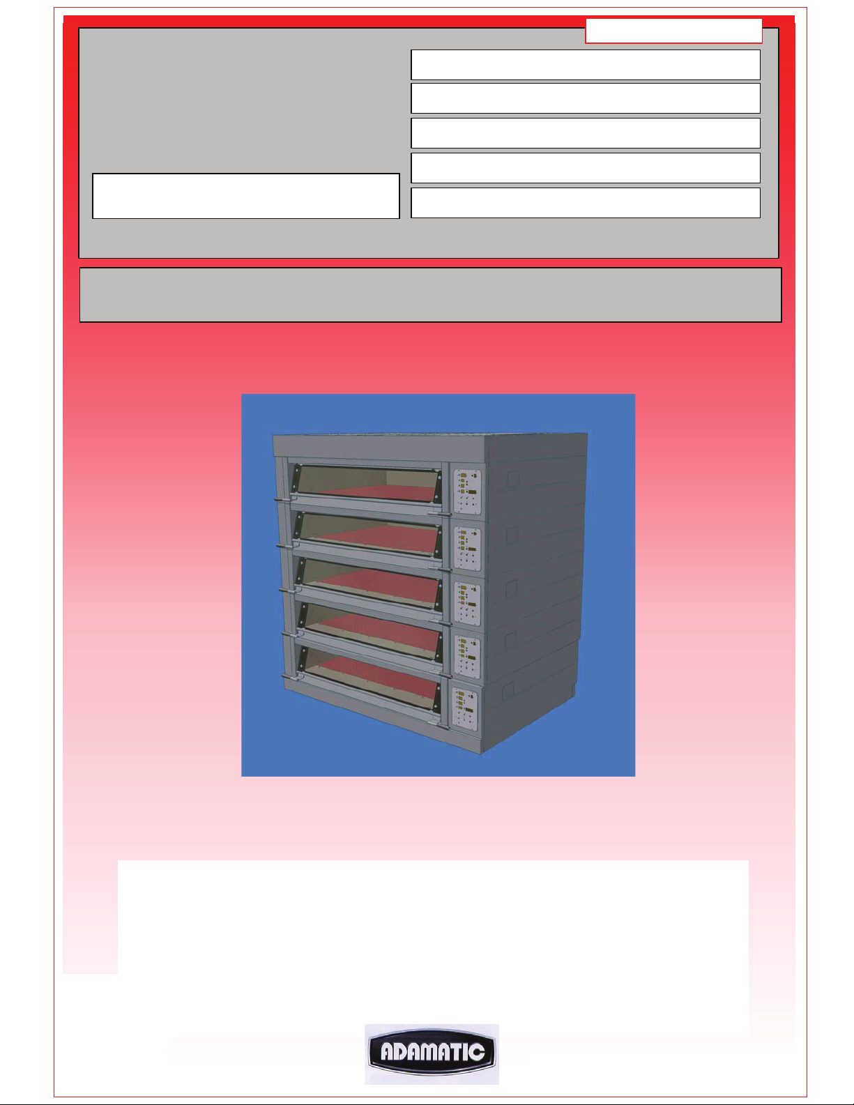
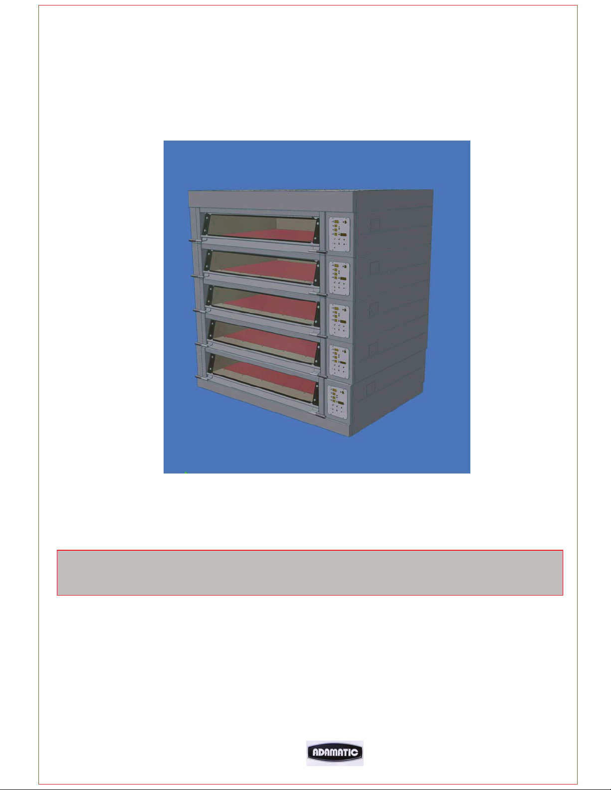
MODULAR DECK OVEN
FG257 MODULAR DECK 02/07 RAC
1
Page 2
r
WARNING LABEL, TO REDUCE RISK OF FIRE
OR ELECTRIC SHOCK
DO NOT REMOVE COVER (OR BACK)
NO USER SERVICEABLE PARTS INSIDE
REPAIR SHOULD BE DONE BY AUTHORISED PERSONNEL ONLY
Failure to adhere to the cleaning and maintenance instructions
detailed in this booklet could affect the warranty of this
machine.
The oven should only be used for baking bread, pastries and cakes
(for other products please contact your oven supplier)
DISPOSAL
Care should be taken when the machine comes to the end of its working
life. All parts should be disposed of in the appropriate place, eithe
recycling or other means as the law permits at the time.
ENGINEERS NOTE
IF THESE NUMBERS APPEAR IN THE TEMPERATURE WINDOW
PLEASE CHECK THE FOLLOWING:
888 – Indicates that the control board is above 80 degrees
Check that the cooling fan entry is not blocked
(oven glove etc)
999 – Indicates a problem with the thermocouple.
Check for connection problems or faulty thermocouple.
MONO FG257 HARMONY MODULAR DECK 01/07 RAC
2
Page 3
CONTENTS
Section - 1.0 Introduction
Section - 2.0 Overall Dimensions
Section - 3.0 Specifications
Section - 4.0 Safety
Section - 5.0 Installation
Section - 6.0 Isolation
Section - 7.0 Cleaning
Section - 8.0 Operating Conditions
Section - 9.0 Principles Of Operation
(and baking advice)
Section - 10.0 Operating Instructions
Section - 11.0 Troubleshooting
Section - 12.0 Service Information
Replacing light bulbs
Section - 13.0 Spares Information
THIS SECTION IS FOR ENGINEERS ONLY AND THE CUSTOMER
SHOULD NOT ATTEMPT TO MAKE ALTERATIONS.
Section - 14.0 Electrical Information
Section - 15.0 WARNING and INFORMATION LABELS
FG257 MODULAR DECK 02/07 RAC
3
Page 4

1.0 INTRODUCTION
The electric modular Deck Oven is an easy to use practical, good-looking oven,
giving an excellent heat recovery rate and an even bake across a wide range of
bread and confectionery products.
x Good looking and totally reliable
Conceived with the no nonsense requirements of both the independent and in-store
baker in mind, and designed to visually please as well as give reliable service for
many years. This oven will more than satisfy the most discerning customer.
x Top quality specification
The external and internal contact surfaces are stainless steel.
Each modular deck is fitted with durable reinforced one-piece tiles, and an increase
in high-grade insulation and high temperature ceramic sealant, makes the oven more
efficient.
The oven comes with a patented integral steaming system, which reduces energy
consumption and the overall size of the oven (no drain required). The system
produces real steam with the advantages of spray steam. Pre-steam is also available
to reduce the affects of long loading times.
No drainage is required.
Supplied with an LED screen. All programmable parameters have separate indicators
for easy programming and extra bake time, if required. An energy saving 7-day timer
is also standard.
The simplified electrical circuits aid reliability with overheat protection (on controllers
and oven) to ensure long life of controllers, all housed in splash-proof electrical
enclosures. The lights are low voltage, sealed from the chamber and easily accessed
from outside the oven.
An “i” button can be used to upgrade firmware without the need of dismantling the
panels.
Fitted with a choice of hinged easy to clean double glazed doors (using low energyloss reflective glass for high visibility) or metal doors, means low energy consumption
and the high kW rating gives good recovery.
(0-100% heating available both top and bottom)
FG257 MODULAR DECK 02/07 RAC
4
Page 5
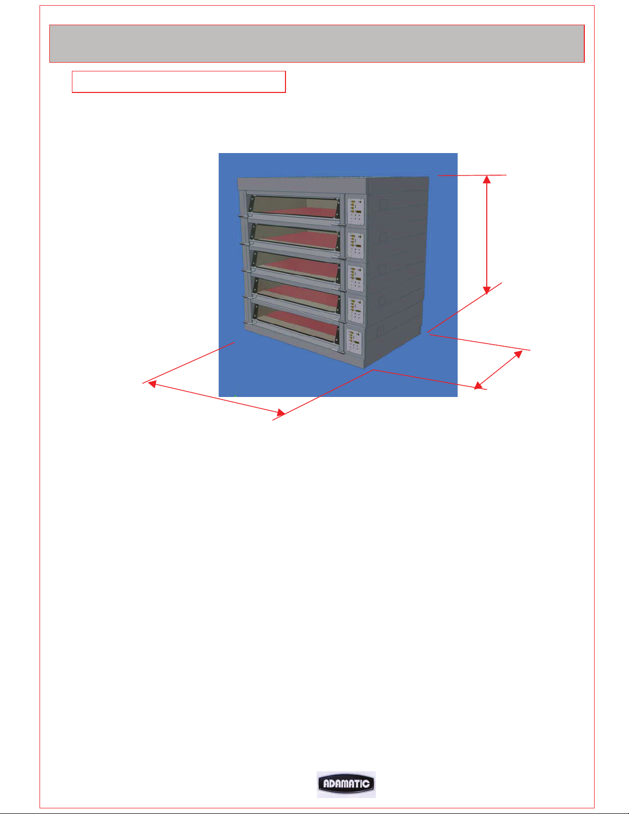
2.0 OVERALL DIMENSIONS
ALL DIMENSIONS ARE APPROXIMATE
All ovens……………….H = 80” (2040mm)
Ovens available with 1,2,3, 4, and 5 modules
32” deep modules …... D = 51 ¾” (1300mm)
3 Tray wide oven ……. W = 74 ½” (1890mm)
2 Tray wide oven ……. W = 55 ¾” (1416mm)
1 Tray wide oven ……. W = 37” (940mm)
MONO FG257 HARMONY MODULAR DECK 01/07 RAC
5
Page 6
3.0 SPECIFICATIONS
Dimensions in millimetres
25.4mm = 1”
5 DECK OVEN
DECK PLATE HEIGHTS
4 DECK OVEN
DECK PLATE HEIGHTS
3 DECK OVEN
DECK PLATE HEIGHTS
FG257 MODULAR DECK 02/07 RAC
6
Page 7

FG257 MODULAR DECK 02/07 RAC
FG257 MODULAR DECK 02/07 RAC
7
7
Page 8
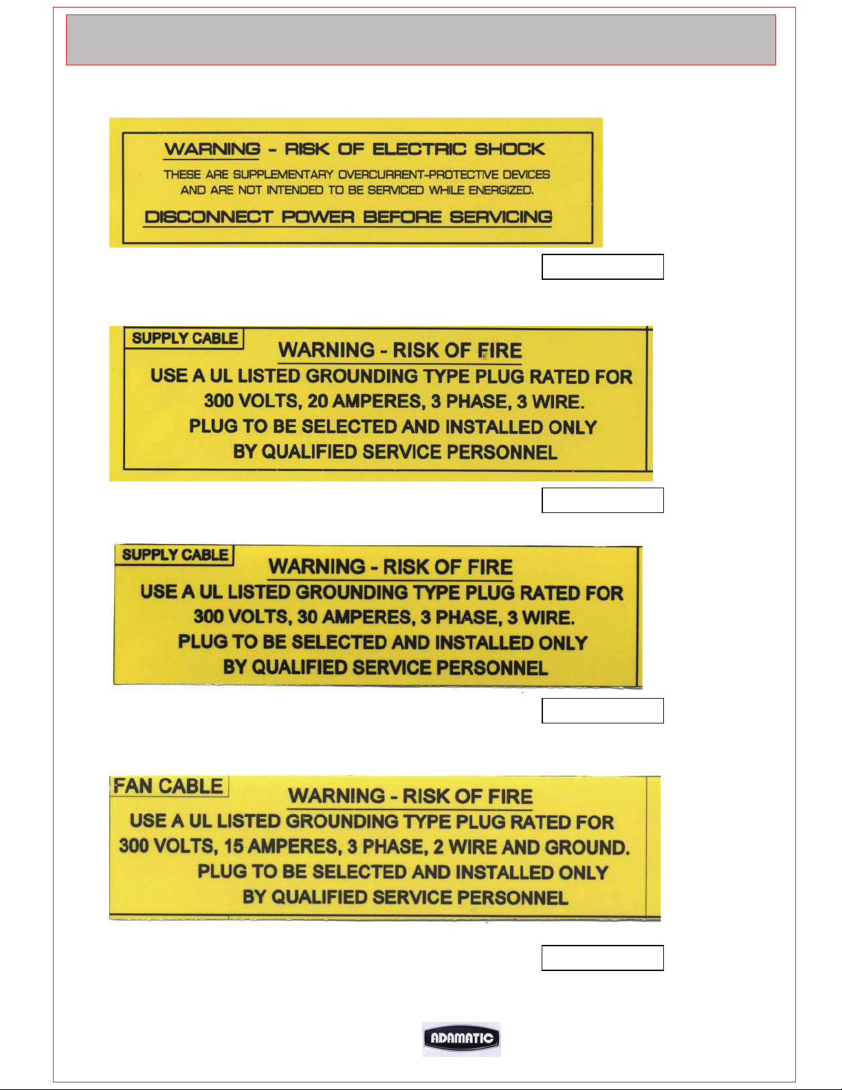
ELECTRICAL LOADINGS:
SUPPLY REQUIRED PER MODULAR DECK: x
3 TRAY WIDE 2 TRAY WIDE 1 TRAY WIDE
3 Phase (3 wire + ground), 220V. 60Hz 8.85kW, 24Amp 5.93kW,18Amp 3.0kW, 9Amp
3 Phase (3 wire + ground), 208V. 60Hz 7.90kW, 22Amp 5.31kW,17Amp 2.7kW, 8.7Amp
OVERLOAD PROTECTION 30AMPS 30AMPS
3 Phase (3 wire + ground), 480V. 60Hz 8.78kW, 12.4Amp 5.86kW,8.2Amp 4.9kW, 7Amp
OVERLOAD PROTECTION 20AMPS 20AMPS
SUPPLY REQUIRED FOR CANOPY: x
1 Phase (2 wire + ground), 220V. 60Hz Fused at 6Amps
1 Phase (2 wire + ground), 208V. 60Hz Fused at 6Amps
NOISE LEVEL: Less than 80 Db
WEIGHT:
(ALL WEIGHTS ARE APPROXIMATE)
Total oven weight – 2 tray wide, 3 deck = 1569lbs (711kg)
(Including base frame) – 3 tray wide, 3 deck = 2345lbs (1064kg)
– 1 tray wide, 3 deck = TBA
Weight per oven chamber module – 2 tray wide = 421lbs (191.5kg)
– 3 tray wide = 575lbs (261kg)
– 1 tray wide = TBA
Weight per oven canopy module – 2 tray wide = 31lbs (14kg)
– 3 tray wide = 38lbs (17kg)
– 1 tray wide = TBA
Weight per fan module – 2 tray wide = 62lbs (28kg)
– 3 tray wide = 62lbs (28kg)
– 1 tray wide = TBA
Weight of product (max) per deck – 2 tray wide = 86lbs (39kg)
– 3 tray wide = 131lbs (60kg)
– 1 tray wide = TBA
FG257 MODULAR DECK 02/07 RAC
8
Page 9
4.0 SAFETY
All maintenance must be made with the oven disconnected from the
power supply and then only by fully trained authorized persons.
Check all cover panels, and any pipefittings are securely positioned.
Check oven door handles are not damaged.
Do not operate a deck's steaming system with oven door open.
Always use oven gloves when loading the oven.
When products are removed from the oven, ensure:
(a) Tins are knocked out and stored directly onto tin storage trolley or rack
(Do not leave hot tins on the floor or on tables).
(b)Trays are put into a rack and the rack is wheeled to a safe cooling area.
Do not store items on top of the oven.
Do not store items behind the oven.
Beware of hot surfaces. Do not touch oven front or door with bare skin.
All operatives must be fully trained
People undergoing training must be under direct supervision
The oven should only be used for baking bread, pastries and cakes (for other
products please contact your oven supplier)
No unauthorized modifications should be made to the oven.
Do not walk on the roof of the oven
DISPOSAL
Care should be taken when the oven comes to the end of its working life. All
parts should be disposed of in the appropriate place, either recycling or other
means as the law permits at the time.
NOTE: BAKERY STAFF MUST NOT UNDER ANY CIRCUMSTANCES REMOVE
PANELS TO ACCESS ANY PART OF THE DECK OVEN.
Panels should only be removed by an Adamatic maintenance engineer (or other
fully trained maintenance contractor) for repairs or maintenance, after isolating
oven from power supply.
The Bakery Manager or the Bakery Supervisor must carry out the above daily safety checks
MONO FG257 HARMONY MODULAR DECK 01/07 RAC
9
Page 10
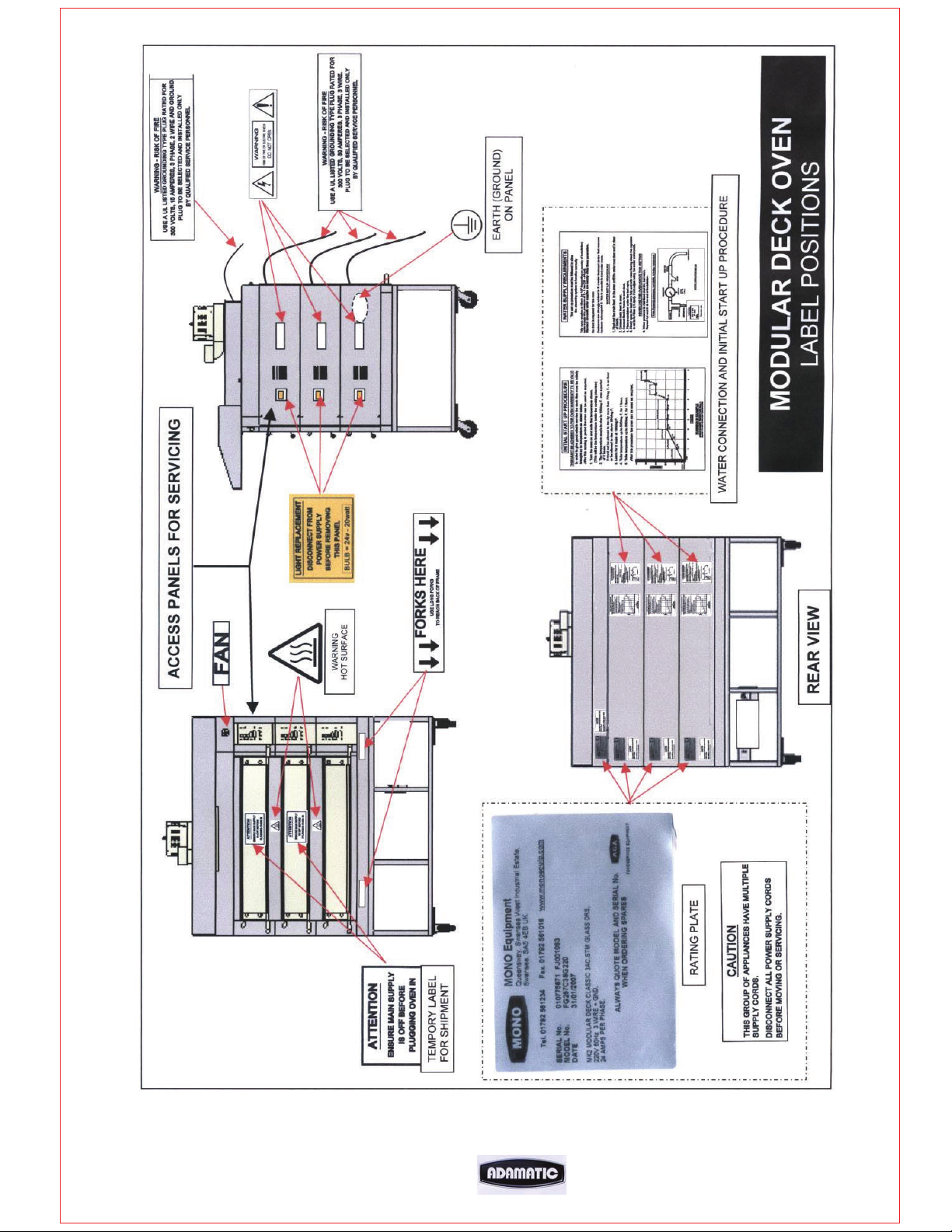
5.0 INSTALLATION
GENERAL
A hard smooth level floor is recommended on which to position the oven and
access for maintenance should be considered.
The oven is not designed to be ” built in” so sufficient clearance must be left in
front of the access panels (right hand side) to allow for servicing.
If not chosen as an oven option, it is recommended that an extraction hood be
placed above the oven to disperse excess steam and heat, which could have
an adverse effect on the bakery ceiling and ambient temperature.
A wall isolator rated at 30Amps must be available in order to completely
x
isolate the oven.
THIS ISOLATOR MUST BE CLEARLY ACCESSIBLE TO THE OVEN OPERATOR
A chain retainer should be fitted, that is shorter than the power cables, to
x
protect them from strain if the oven is moved. (Fit to the wall or floor and the
base, using hole provided in castor fixing corner plates).
x Installation must be made by a trained authorized engineer and all utilities
must be installed by licensed contractors and must conform to all local and
state building codes.
The oven must be “run in” as stated in the initial start up instructions.
ELECTRICAL CONNECTIONS
Each modular deck requires its own power supply.
SUPPLY REQUIRED PER MODULAR DECK:
3 TRAY WIDE 2 TRAY WIDE 1 TRAY WIDE
3 Phase (3 wire + ground), 220v. 60Hz 8.85kW, 24Amp 5.93kW,18Amp 3.0kW, 9Amp
3 Phase (3 wire + ground), 208v. 60Hz 7.90kW, 22Amp 5.31kW,17Amp 2.7kW, 8.7Amp
OVERLOAD PROTECTION 30AMPS 30AMPS
3 Phase (3 wire + ground), 480v. 60Hz 8.78kW, 12.4Amp 5.86kW,8.2Amp 4.9kW, 7Amp
OVERLOAD PROTECTION 20AMPS 20AMPS
SUPPLY REQUIRED FOR CANOPY: x
1 Phase (2 wire + ground), 220v. 60Hz Fused at 6Amps
1 Phase (2 wire + ground), 208v. 60Hz Fused at 6Amps
MONO FG257 HARMONY MODULAR DECK 01/07 RAC
10
Page 11
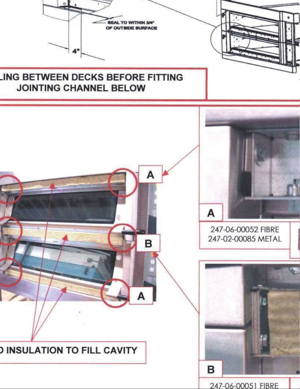
Page 12
IMPORTANT OPERATION
EARTH (GROUND)
STRAPS MUST BE
CONNECTED
BETWEEN EACH
SECTION.
REAR VIEW OF OVEN
PART NUMBER
M158-25-11200
SUPPLIED
FG257 MODULAR DECK 02/07 RAC
11
Page 13

WATER SUPPLY REQUIREMENTS
The set up procedure on the next page must be followed to
allow the steaming system to function correctly
THIS EQUIPMENT IS TO BE INSTALLED TO COMPLY WITH THE
APPLICABLE FEDERAL, STATE, OR LOCAL PLUMBING CODES
All ovens with steam require a ½” NPT hot or cold water supply at a pressure
of 2 - 3 bar (29 – 44 psi). Located approximately 10” from the right and 4” from
the top of the stand when facing the front of the oven.
Only one water supply is required per oven. A manifold supplies all decks from
one connection point.
For proper operation of the steam system it is recommended that the water
supply follows the following specifications:
Hardness 2-4 grains per gallon
PH range 7.0 to 8.0
Chloride concentration 0 –30 ppm
Consult your water treatment company for proper water filtration system
information.
No drain is required for this oven.
A non-return check-valve is supplied fitted to the water inlet manifold.
MONO FG257 HARMONY MODULAR DECK 01/07 RAC
12
Page 14
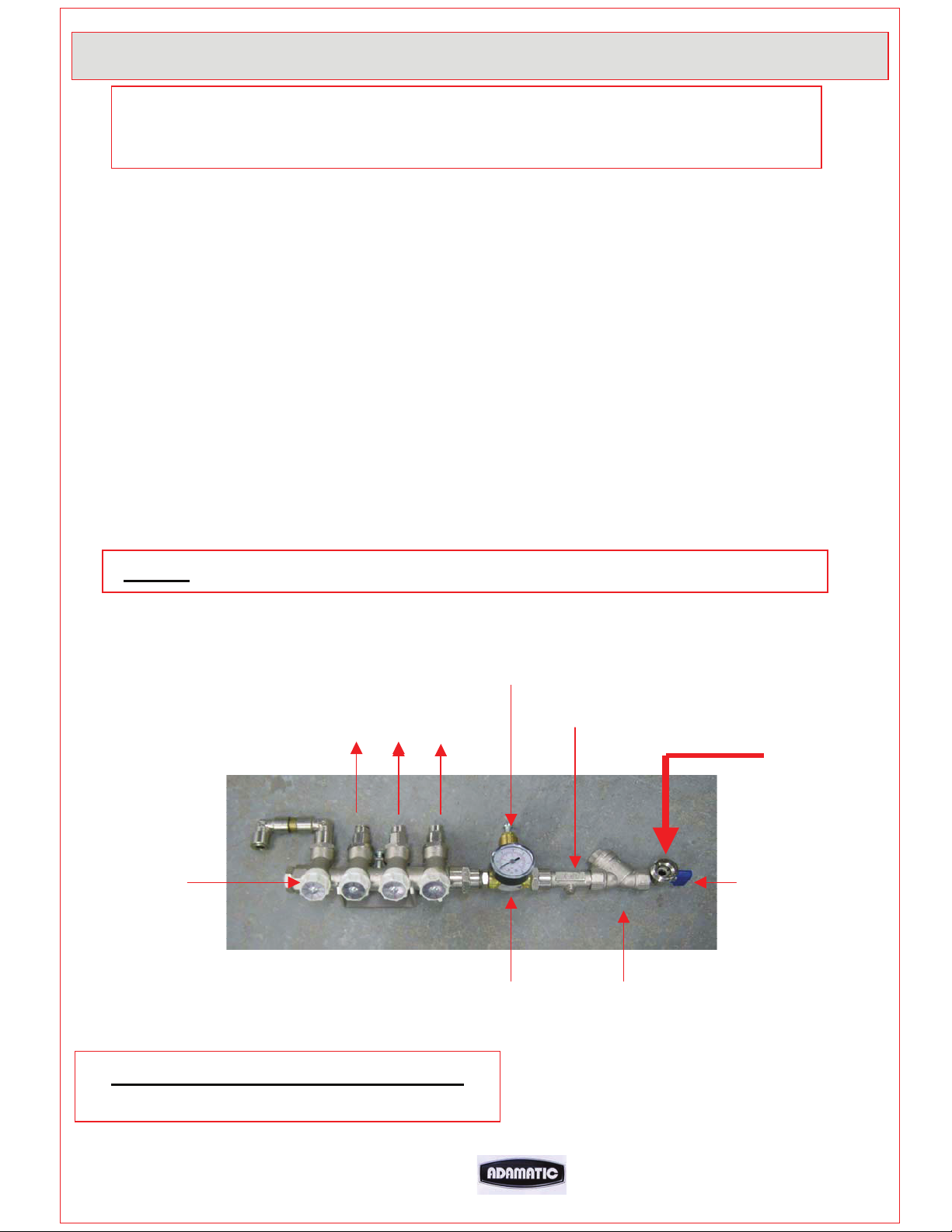
WATER SYSTEM SETUP PROCEDURE
It is imperative that the water delivery to the deck oven is checked for the
steam system to operate correctly
1. Flush out the main feed pipe to be used, until water runs clear and free from debris.
2. Connect main feed to oven.
3. Connect flexible hoses to each deck.
4. Place a container under the test valve.
5. Slowly open test valve fully and with the water flowing check the regulator is set to
0.75 bar. If not adjust using the screw above the valve.
x Never use the oven above this setting
6. When the pressure has stabilised shut the test valve.
REPEAT 4,5 AND 6 AT THE END OF INSTALLATION.
NOTE. DYNAMIC PRESSURE, NOT STATIC, IS BEING MEASURED.
ADJUSTING SCREW
SET TO 0.75 bar
TO OVENS
TEST VALVE
WATER REGULATOR SET UP
LOCATED ON REAR OF OVEN
RESTRICTOR
REGULATOR
FROM SUPPLY
CHECK VALVE
STOP TAP
FILTER
FG257 MODULAR DECK 02/07 RAC
13
Page 15
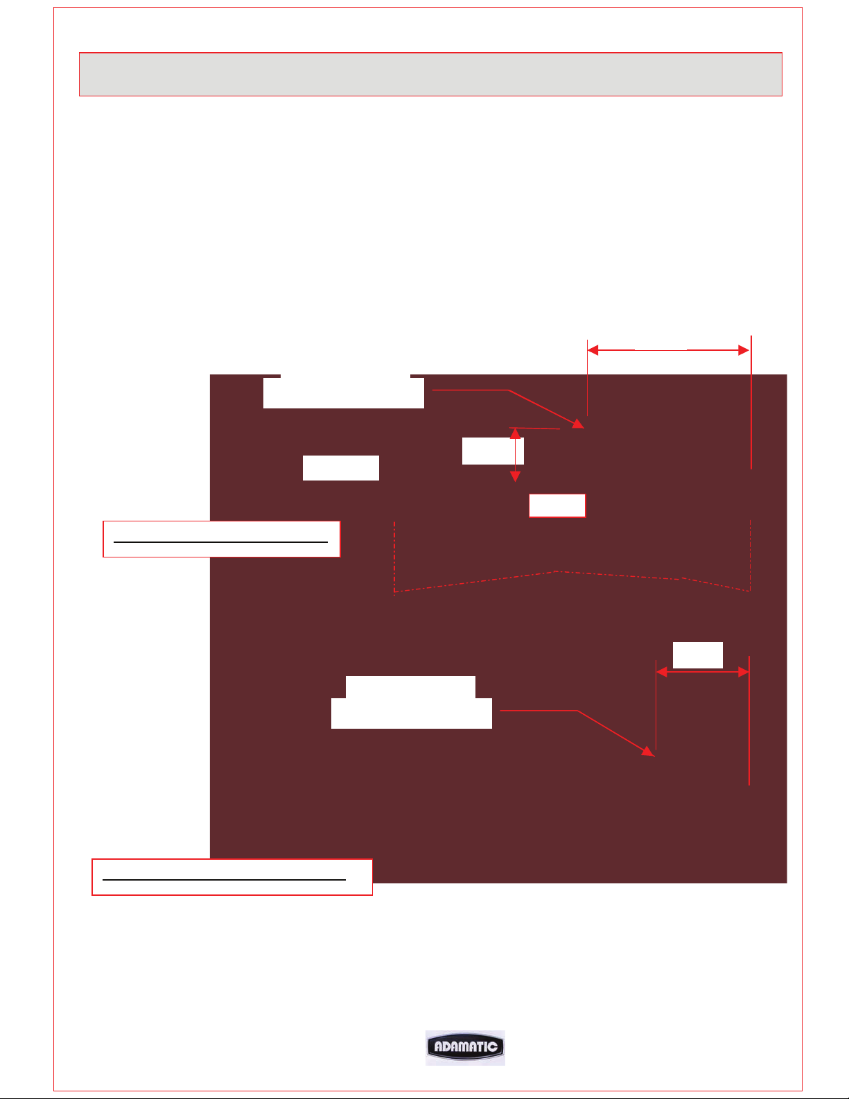
Exhaust Connections (IF CANOPY FITTED)
x Ideally an exhaust duct should rise 78” (2 metres) above the bakery roof
protected from wind and birds by a duct protector.
x It should be of a suitable material to take the high temperatures and humidity
expected.
x It should be flexible and easily removable at the oven connection point.
This allows the oven to be moved for cleaning when required.
10” Dia.SPIGOT
CONNECTION POINT
23”
CANOPY
WITH EXTRACTION FAN FITTED
9 ½”
ROOF
13”
10” Dia.SPIGOT
CONNECTION POINT
WITHOUT EXTRACTION FAN FITTED
FG257 MODULAR DECK 02/07 RAC
14
Page 16
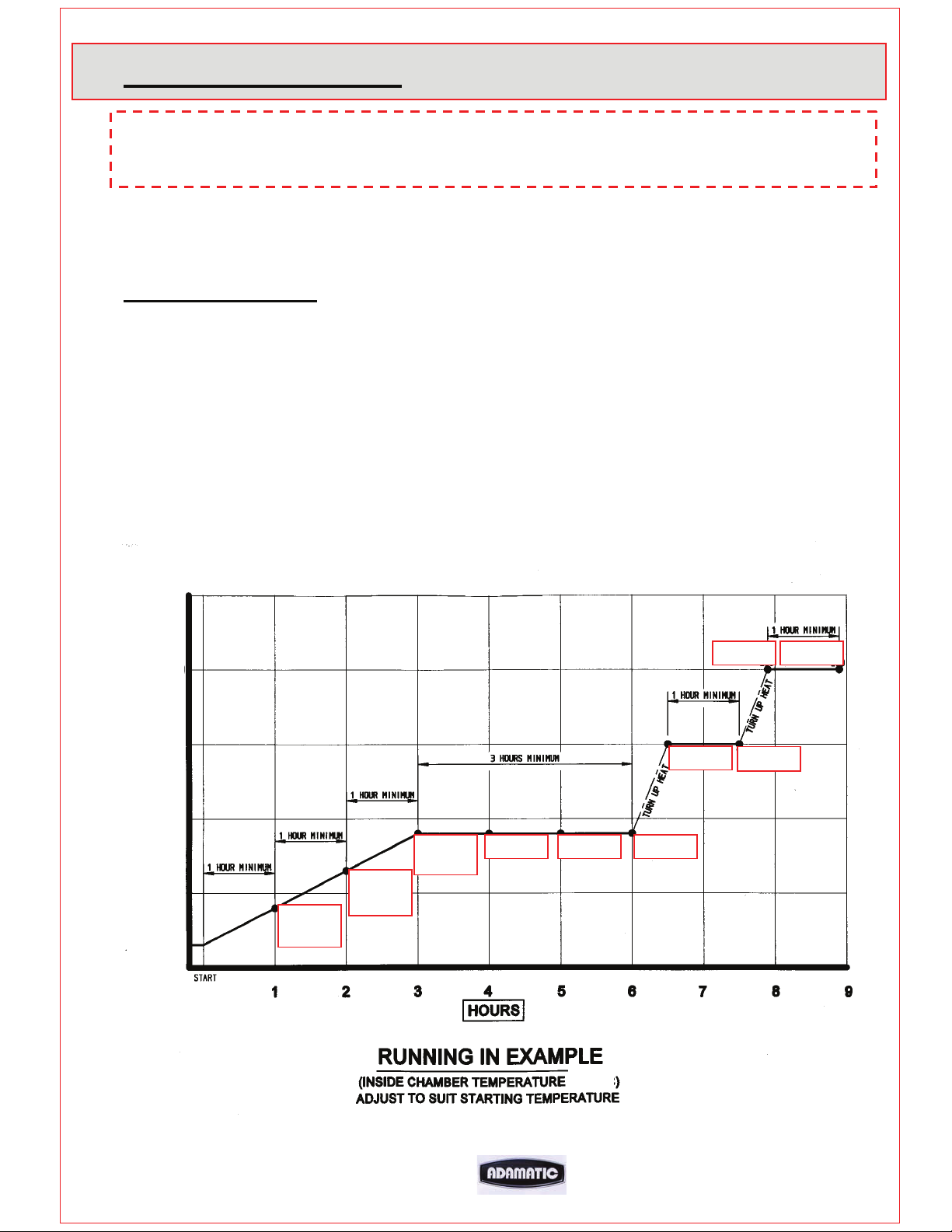
INITIAL START UP
THIS PROCEDURE MUST BE ADHERED TO FOR THE OVEN
WARRANTY TO BE VALID.
In order for the oven to give good reliable service the deck tiles must be initially
brought up to temperature as stated below. After this running in period the oven can
be used as required.
Running in procedure
1. Turn the oven on and note the temperature shown.
(This will be the temperature inside the cooking chamber)
2. The temperature needs to rise to 195deg F over a period of 3 hours.
It must not be allowed to rise by more than 77deg F in an hour or
be allowed to rise above 200deg F.
3. Leave for 3 hours at 195deg F.
4. Take the temperature up to 300deg F for 1 hour.
5. Take the temperature up to 390deg F for 1 hour.
After this procedure the oven can be used as required.
482f
392f
302f
212f
122f
60f
77-104
MAX
77-150
MAX
77-195
MAX
77-195 77-195 77-195
302
77-1392 04 392
302
FG257 MODULAR DECK 02/07 RAC
15
Page 17
6.0 ISOLATION
WARNING
THE “POWER OFF” BUTTON ON THE FRONT OF THE OVEN DOES NOT
ISOLATE THE POWER SUPPLY.
A WALL ISOLATOR RATED AT 30AMPS MUST BE
AVAILABLE IN ORDER TO COMPLETELY ISOLATE THE
OVEN.
THIS ISOLATOR MUST BE CLEARLY ACCESSIBLE
AND KNOWN TO THE OVEN OPERATOR
TO STOP THE OVEN IN AN
EMERGENCY SWITCH OFF AT THE
MAIN WALL ISOLATOR
MONO FG257 HARMONY MODULAR DECK 01/07 RAC
16
Page 18

7.0 CLEANING
DAILY CLEANING INSTRUCTIONS
ISOLATE OVEN FROM MAINS SUPPLY BEFORE CLEANING.
After the oven has been allowed to cool, (this could take several hours),
sweep any debris out.
Use a vacuum cleaner with metal attachments (able to take heat) if available.
Brush down and wipe oven front, back and sides with a damp cloth.
Spot clean with a damp cloth, which has been soaked in a solution of mild
detergent, and hot water, paying particular attention to ensure excess water is
not applied around the area of the electrical panels.
NOTE: TAKE CARE WATER DOES NOT ENTER CONTROL PANEL
MOUNTING OR ROOF MOUNTED FAN.
WEEKLY CLEANING INSTRUCTIONS
ISOLATE OVEN FROM MAINS SUPPLY BEFORE CLEANING.
Complete daily cleaning as above.
Scrub oven wheels with a mild detergent and hot water using nylon cleaning
brush (excess water will rust metal).
Ensure the oven roof area is clear of debris and dust build up.
(DO NOT STAND ON THE OVEN ROOF)
MONO FG257 HARMONY MODULAR DECK 01/07 RAC
17
Page 19
8.0 OPERATING CONDITIONS
It is recommended that a space of at least 6 feet be left in front of the oven for
ease of operation and safety.
Bakery utensils must not be used to operate the control panel buttons.
9.0 PRINCIPLE OF OPERATION
NOTE: REFER TO YOUR OWN COMPANY’S RECIPE MANUAL FOR OVEN
TEMPERATURE SETTINGS.
PLEASE ALSO REFER TO THE BAKING ADVICE ON THE NEXT PAGE
Products are baked in an insulated heated chamber. The temperature is regulated by
a thermocouple having an LED read-out on the front control panel. Baking heat is
radiant with top and bottom heat being adjusted by means of separate controls. This
enables heat to be “balanced” according to product requirement.
STEAM is provided from an integral steam unit, and is introduced into the chamber
on demand. This is automatically controlled by the programmed parameters. Once
steamed the oven will not steam until the steam unit has recovered heat,
typically 3-8 minutes depending on the amount of steam selected.
All ovens are fitted with a steam damper that evacuates steam humidity into a vent
at the side of the oven.
FG257 MODULAR DECK 02/07 RAC
18
Page 20

Baking Advice
For the best results from deck Ovens
Loading
1. Do not place the products too close together. If the loaves are close to
each other after oven spring (expansion), the loaves sides will be soft and may
collapse on cooling.
2. Place the product evenly within the oven. Product bunched together will be
paler than those widely spaced.
3. Product should not be placed too close to the edge of the tile. As it
expands towards the front one side of the loaf may enter the cooler air by the
door.
4. Door opening should be kept to a minimum because cold air enters the
oven cooling the sidewalls and roof causing the finished product to be lighter
locally at the front and wasting heat. If loading times are consistently long you
can alter the front top heat to put more heat at the front.
5. If the loading takes a long time product can form a skin, which causes an
imbalance and a less attractive finish. By using the pre-steam function before
loading this can be minimised. This function turns the elements off and injects
steam to increase the humidity.
6. If whilst baking, the bake is found to be consistently dark or light at the
front the front top element can also be adjusted for local fluctuations in
voltage.
Bake settings
1. A good starting point for baking breads in deck ovens is 437F (225C)
Top heat 140F-150F, bottom heat 104F.
2. For cookies etc the heat in the oven can be turned almost off, however it may
still be necessary to place the trays with cookies etc onto upturned trays on
the oven sole.
3. Steam should be kept to a minimum, for energy efficiency, depending on the
product and finish. Times between 9 and 12 seconds should be adequate.
4. It is a good idea not to focus on the temperature recovery this can vary from
oven to oven.
FG257 MODULAR DECK 02/07 RAC
19
Page 21

Is the product baked in the time and to the quality you require?
Below are some tips for modifying the bake so you get the product that you require.
x If your product is light on top.
Either decrease the bottom heat and extend bake time or increase the top heat.
x If the product sides are pale and the top dark.
When the products are spaced well apart drop the top heat and extend the bake.
x If the bake time is too long.
First increase the top heat to speed recovery.
If this does not give sufficient savings increase the bake temperature.
x To thicken the crust
Set the damper to open longer. Different ovens will require different lengths of time.
MONO FG257 HARMONY MODULAR DECK 01/07 RAC
20
Page 22
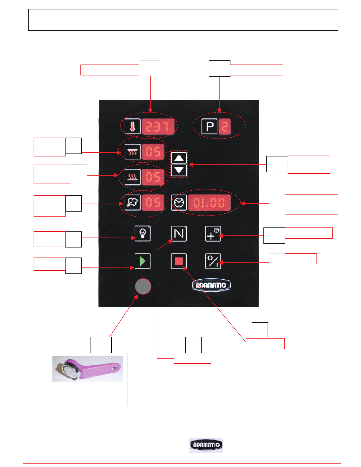
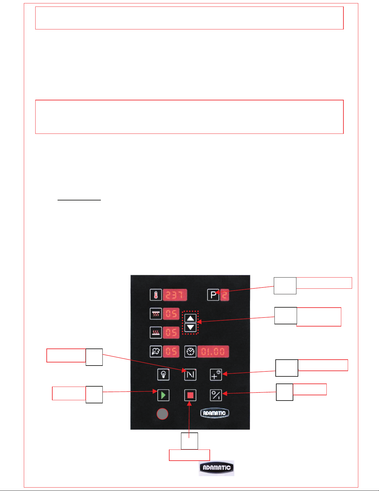
ON/O
CLASSIC DECK OVEN CONTROLLER
TOP
HEAT
BOTTOM
HEAT
STEAM
TIME
TEMPERATURE
9
8
7
10
11
PROGRAM
12
5
UP/DOWN
AUTO ON SET /
ADD TIME
LIGHT
START
4
3
14
“iButton”
STORAGE DEVICE
CONNECTION
6
DAMPER
13
2
STOP
1
BAKE TIME
FF
FG257 MODULAR DECK 02/07 RAC
21
Page 23

1. ON/OFF
Turns controller on from standby mode.
Also used to exit setup mode.
2. STOP
Stops bake cycle.
Also used to go to function setup menu on power up (with button 3)
3. START
Starts bake cycle.
Also used to go to setup menu on power up (with button 2)
Also silences “2 minutes from end of bake” alarm when sounding.
4. LIGHT
Interior light on/off.
Red light shows when light is on.
Press to turn on and press again to turn off.
5. BAKE TIME/ADD TIME
Used to access set bake time and current time and day setup.
Also used to jump to day/hours/minutes when setting time and setting auto
on time.
IF 7 DAY TIMER ENABLED
During bake cycle, Used to add extra bake time (1 minute each press).
At end of bake, press for two minutes and then once for each extra
minute required.
6. DAMPER
Press to open damper. Press again to close damper.
(only works during bake).
Closes when stop pressed at end of bake and while steaming.
Red light shows when in open position.
7. STEAM TIME
Press to access steam time and pre-steam mode.
If pre-steam function is enabled.
Press once (reds dots appear).Use up down keys (12) to change to required
setting. P0 = no pre-steam, P1 = 1 second, P2 = 2 seconds.
Press again to set steam time using up and down keys (12).
Press button again to save or wait 10 seconds to auto-save.
If pre-steam function is not enabled.
Press to set steam time using up and down keys (12).
Press button again to save or wait 10 seconds to auto-save.
8. BOTTOM HEAT
Press to set the bottom heat cycle percentage. Use up and down keys (12)
to adjust the value.
Press button again to save or wait 10 seconds to auto-save.
9. TOP HEAT
Press to set the top heat cycle percentage. Use up and down keys (12) to
FG257 MODULAR DECK 02/07 RAC
adjust the value.
Press button again to save or wait 10 seconds to auto-save.
22
Page 24
10. TEMPERATURE
11. PROGRAM
12. UP/DOWN BUTTONS
13. AUTO ON SET / ADD TIME
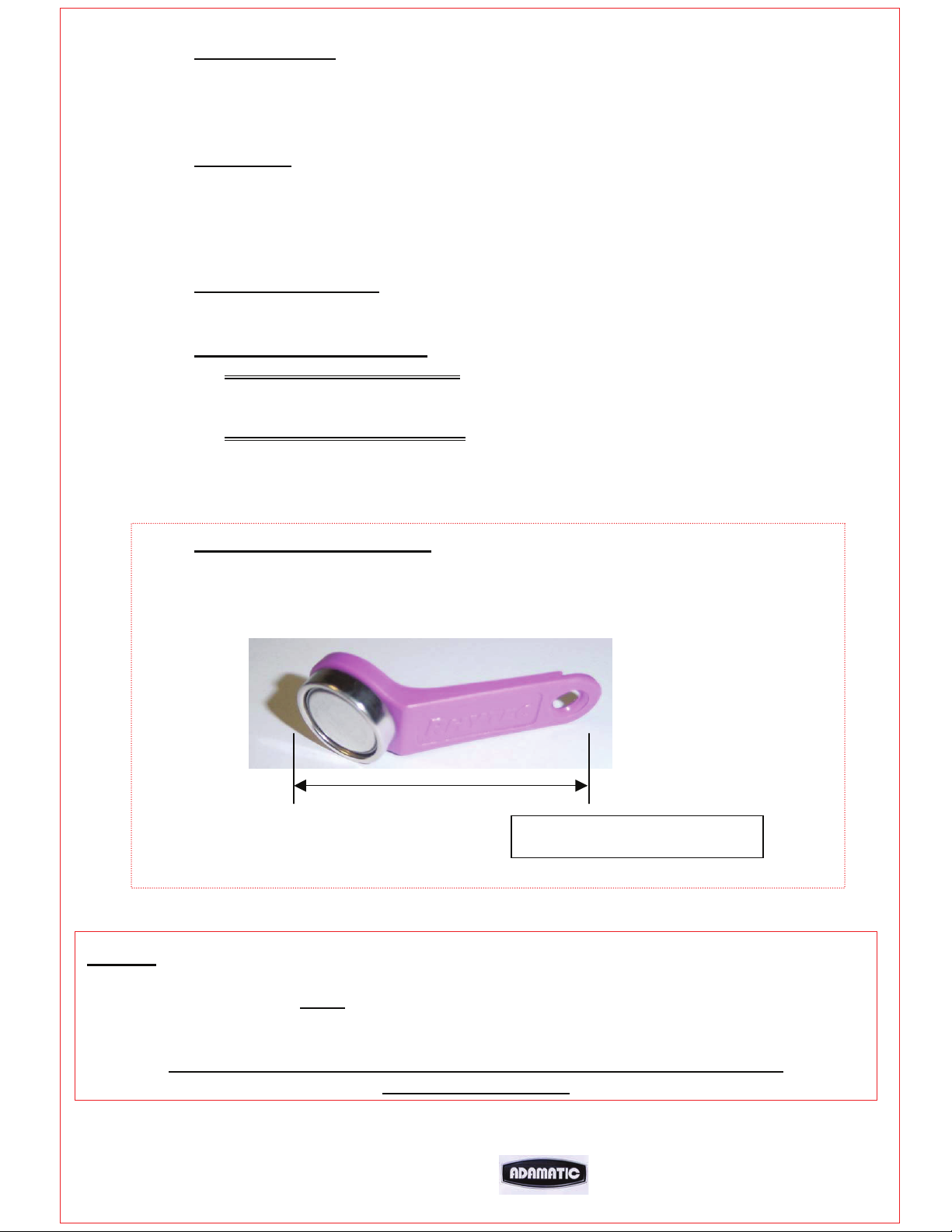
14. “i BUTTON” CONNECTION
NOTE
Press to set the bake temperature required. Use up and down keys (12) to
adjust the value.
Press button again to save or wait 10 seconds to auto-save.
Use up and down keys (12) to go to required program.
Press “p” for 5 seconds and all displays will flash.(A beep confirms settings
are now saved)
Used to adjust values when required.
IF 7 DAY TIMER ENABLED
Used to access auto switch on times.
IF 7 DAY TIMER DISABLED
During bake cycle, Used to add extra bake time (1 minute each press).
At end of bake, press for two minutes and then once for each extra
minute required.
Used with special “iButton” storage device to change firmware of control
board.
2”
“I Button” storage device
Whenever power is connected to the board, 8 minutes
must
elapse before the oven will steam.
This allows the bottom elements to heat enough for steaming.
This will always happen if the power is disconnected and connected again,
even if the oven is hot.
FG257 MODULAR DECK 02/07 RAC
23
Page 25
OPERATION
1. With oven in standby mode (power on) press “on” button (1).
2. Press program button (11)
Using up and down keys (12) choose the set program required.
Oven will heat to the temperature required. Oven is ready for use when the display
shows the temperature of the program chosen and if steam is required the display
stops flashing.
Note:
If the oven is already hot and the set temperature is lower than the current temperature of
the oven, the door should be opened to allow the temperature to drop.
3. Load oven as required.
To preserve heat, do not leave doors open more than needed to load oven.
4. Press start (3)
Press (13) at anytime during the bake to add 1 minute to the bake time.
DAMPER (6) Press to open damper. Press again to close damper
Red light shows when in open position.
(Closes if left open for 90 minutes)
5. 2 minutes from the end of the bake the buzzer will sound for 10 seconds.
6. At the end of the bake the buzzer will sound again. Press stop (2).
Press start (3) to silence if required.
DAMPER
START
FG257 MODULAR DECK 02/07 RAC
6
3
2
STOP
11
12
13
1
PROGRAM
UP/DOWN
BUTTONS
BAKE TIME
ON/OFF
24
Page 26

DAY AND TIME SET UP
Turn the power supply on.
This will put the oven in “standby mode” with only the clock showing.
Press clock button (5) and dots will flash under the hours in the time window.
Change value using up and down keys (12).
Press clock button (5) again and dots will flash under the minutes in the time window.
Change value using up and down keys (12).
Press clock button (5) again and day number will show.
Change value using up and down keys (12).
(usually day 1 is used as Monday)
To save the settings press clock button (5) within 5 seconds.
12
UP/DOWN
BUTTONS
CLOCK
DISPLAY
5
CLOCK
BUTTON
FG257 MODULAR DECK 02/07 RAC
25
Page 27

SET UP MODE
To enter set up mode press start (3) and stop (2) buttons
and then turn the power supply on at the same time.
FUNCTION DISPLAY
WINDOW
Change to the function required using up and down keys (12).
(see next page for function list)
Press clock button (5). (Dots appear on display)
Change value using up and down keys (12).
Press clock button (5) to save setting.
To exit set up mode and save changes
NOTE
Any changes to the functions are only saved when exiting using on/off (1)
START
3
F10
250
+
press on/off (1).
2
STOP
12
5
1
UP/DOWN
BUTTONS
ADJUST
VALUE
ON/OFF
PRESS TO
SAVE AND EXIT
FG257 MODULAR DECK 02/07 RAC
26
Page 28

SET UP PARAMETER FUNCTION LIST (“F” SETTINGS)
F1 - MONO CONSTANT (FACTORY SET AT 210C)
F2 - TOP HEAT GAIN (FACTORY SET AT 50)
F3 - BOTTOM HEAT GAIN (FACTORY SET AT 50)
F4 - FRONT TOP ELEMENT OFFSET VALUE (0-50)
F5 - DEG “C”, DEG”F”
F6 - “2 MINUTE FROM END OF BAKE ALARM” (ENABLE=1, DISABLE=0)
F7 - PRE-STEAM - (ENABLE=1, DISABLE=0)
F8 - STEAM - (ENABLE=1, DISABLE=0)
F9 - BAKE TEMPERATURE OFF-SET (+ - 25 DEG C)
F10 - MAXIMUM SET TEMPERATURE LIMIT (250 DEG “C” DEFAULT)
MAXIMUM TEMPERATURE 290 DEG “C”
F11 - BAKE CONTROLS LOCKOUT – (ENABLE=1, DISABLE=0)
(TO PREVENT OPERATOR CHANGING SET BAKE PARAMETERS)
F12 - “POWER SAVE” ENABLE/DISABLE (not in use at this time)
IF OVEN IS NOT USED FOR THIS SET TIME, THE TOP
HEATERS WILL SWITCH OFF AND OVEN WILL MAINTAIN
TEMPERATURE USING BOTTOM ELEMENTS ONLY. ONCE ANY
BUTTON IS PRESSED NORMAL OPERATION OF THE OVEN
RETURNS.
F13 - INTERIOR LIGHT AUTO-TIMEOUT - ON/OFF.
BETWEEN 1 AND 20 MINUTES (0 = disabled)
F14 - 0-9 PROGRAM
F15 - 7 DAY TIMER - (ENABLE=1, DISABLE=0)
IF ENABLED, “SET BAKE” TIME ACTS AS EXTRA TIME BUTTON.
IF DISABLED, “AUTO ON SET” ACTS AS EXTRA TIME BUTTON.
F16 - 8 HOUR COUNT DOWN TIMER - (ENABLE=1, DISABLE=0)
AFTER 8 HOURS THE OVEN WILL TURN OFF (NOT DURING A BAKE
CYCLE).
BEFORE SWITCH OFF, DISPLAYS WILL FLASH AND ALARM WILL
SOUND. IF ANY BUTTON IS PRESSED AT THIS TIME, AN HOUR WILL
BE ADDED TO THE TIMER.
(FACTORY SET AT 25)
FG257 MODULAR DECK 02/07 RAC
27
Page 29

CONTROLLER LAYOUT
OUTPUTS
PIN 1 – 24v
PIN 2 – TOP HEAT OUTPUT
PIN 3 -- TOP FRONT HEAT OUTPUT
PIN 4 – BOTTOM HEAT OUTPUT
PIN 5 – STEAM OUTPUT
PIN 6 – DAMPER OUTPUT
PIN 7 – LIGHT OUTPUT
PIN 8 – CANOPY FAN RELAY OUTPUT
PIN 9 – 24v
PIN 10 – 24v
FG257 MODULAR DECK 02/07 RAC
28
Page 30

11.0 TROUBLESHOOTING
NONE OF THE DECKS SWITCHED ON.
x Is main oven power on?
x Check if bakery main power supply time clock is working (if fitted).
x Is 7-day timer clock set correctly to bring oven on at required time?
ONE DECK HAS NOT SWITCHED ON.
x Check if individual deck timer is set to bring it on at required time.
UNEVEN OR PATCHY BAKE
x Door is being opened too often or too long whilst loading.
(front pale, back burnt).
x Faulty element.
x Top or bottom deck elements not functioning.
x Uneven loading.
x No supply voltage across a phase.
x Adjustment to front element control needed
TEMPERATURE GOING WELL OVER SET TEMPERATURE
When empty the temperature of a deck oven can exceed the set baking temperature.
This overheat is marginal when the deck is full of product. If the elements are
continuing to work after the set temperature has been reached call Adamatic service.
(Please allow up to 60deg.F difference before diagnosing a fault condition),
POOR RECOVERY OF SET TEMPERATURE WHEN LOADED
x The doors may have been left open too long during loading, allowing heat to escape.
x The damper may have been left open during loading or baking allowing heat to escape.
x Top and/or bottom heat may not be working or set at a low value.
x No supply voltage across a phase.
STEAM SYSTEM NOT OPERATING CORRECTLY
See fault-tracing guide.
FG257 MODULAR DECK 02/07 RAC
29
Page 31

12.0 SERVICE
If a fault arises, please do not hesitate to contact the
Customer Service Department at: -
ERROR MESSAGES
IF THESE NUMBERS APPEAR IN THE TEMPERATURE WINDOW
PLEASE CHECK THE FOLLOWING:
888
– Indicates that the control board is above 80 degrees
999 – Indicates a problem with the thermocouple.
Check for connection problems or faulty thermocouple.
MONO FG257 HARMONY MODULAR DECK 01/07 RAC
30
Page 32

LIGHT REPLACEMENT
DISCONNECT FROM POWER SUPPLY BEFORE REPLACING LIGHT BULBS
24v 20w LAMP PART NUMBER … B855-94-008
1
UNSCREW PLATE NEXT TO
LIGHT TO BE REPLACED
2
SLIDE FITTING OUT
3
REMOVE LIGHT FROM HOLDING SLOT
AND UNCLIP FROM CABLE
4
FG257 MODULAR DECK 02/07 RAC
REPLACE LIGHT AND REFIT ALL PARTS
RECONNECT POWER SUPPLY AND TEST
31
Page 33

13.0 SPARES INFORMATION
FG257 MODULAR DECK 02/07 RAC
32
Page 34

OVEN SPARES– 220v. (480v IN BRACKETS)
HEATERS MCB (SEE ELECTRICAL PARTS LIST )
HEATERS MCB (SEE ELECTRICAL PARTS LIST )
HEATERS MCB (SEE ELECTRICAL PARTS LIST )
CONTROL TRANSFORMER MCB B872-22-118
OVERHEAT THERMOSTAT B888-30-015
CONTROL CIRCUIT POWER SUPPLY B801-93-005 (220v)
TOP HEAT B801-08-021
BOTTOM HEAT CONTACTOR B801-08-021
WATER SOLENOID A900-34-349
INTERIOR LIGHT (BULB) B855-94-008
OVEN THERMOCOUPLE B873-95-003
MAIN LED PRINTED CIRCUIT BOARD M257-25-00000
DAMPER SOLENOID B749-83-004
CANOPY FAN RELAY B801-37-001
FROSTED GLASS M257-02-00027
PLAIN GLASS M257-02-00028
DOOR BUMPER STOP M257-03-00027
BAKING TILE 3 ACROSS M257-02-00046
2 ACROSS M257-02-00047
1 ACROSS M257-02-00048
HINGE PIN RHS M257-03-00005
HINGE PIN LHS M257-03-00009
BLACK DOOR HANDLE A900-27-192
DOOR SPRING (3 ACROSS) M257-03-00017
(2 ACROSS) M257-03-00011
WIRE ROPE M257-03-00024
SPRING RETAINING PIN M257-03-00025
PULLEY M257-03-00015
PULLEY SPINDLE M257-03-00013
DAMPER DRIVE COUPLING M257-07-00007
ELEMENT GASKET M245-02-01300
24 v 20w DICHROIC LAMP B855-94-008
B801-93-009 (480v)
FG257 MODULAR DECK 02/07 RAC
33
Page 35

ELEMENT SPARES
3 ACROSS
220v 480v
TOP HEAT ELEMENT 1.0kW B854-04-090 (B854-04-096)
TOP HEAT ELEMENT 0.6kW B854-04-088 (B854-04-094)
BOTTOM HEAT ELEMENT 0.75kW B854-04-089 (B854-04-095)
2 ACROSS
TOP HEAT ELEMENT 0.65kW B854-04-099 (B854-04-105)
TOP HEAT ELEMENT 0.4kW B854-04-097 (B854-04-103)
BOTTOM HEAT ELEMENT 0.5kW B854-04-098 (B854-04-104)
1 ACROSS 220V
TOP HEAT ELEMENT 0.325kW B854-04-108
TOP HEAT ELEMENT 0.2kW B854-04-106
BOTTOM HEAT ELEMENT 0.25kW B854-04-107
1 ACROSS 480V
TOP HEAT ELEMENT 0.525kW (B854-04-114)
TOP HEAT ELEMENT 0.325kW (B854-04-112)
BOTTOM HEAT ELEMENT 0.40kW (B854-04-113)
FG257 MODULAR DECK 02/07 RAC
34
Page 36
14.0 ELECTRICS
FG257 MODULAR DECK 02/07 RAC
35
Page 37

PARTS LIST FOR DRAWINGS FOLLOWING – 3 TRAY WIDE – 220v. (480v IN BRACKETS)
P
ARTS LIST FOR DRAWINGS FOLLOWING – 2 TRAY WIDE – 220v. (480v IN BRACKETS)
F1 HEATERS MCB B872-22-115 (B872-22-113)
F2 HEATERS MCB B872-22-115 (B872-22-113)
F1 HEATERS MCB B872-22-114 (B872-22-112)
F3 HEATERS MCB B872-22-115 (B872-22-113)
F
2 HEATERS MCB B872-22-114 (B872-22-112)
F3 HEATERS MCB B872-22-114
F4 CONTROL TRANSFORMER MCB B872-22-118
F5 OVERHEAT THERMOSTAT B888-30-015
F
4 CONTROL TRANSFORMER MCB B872-22-118
F5 OVERHEAT THERMOSTAT B888-30-015
T1 CONTROL CIRCUIT POWER SUPPLY B801-93-005 (B801-93-009)
K1 TOP HEAT CONTACTOR B801-08-021
T1 CONTROL CIRCUIT POWER SUPPLY B801-93-005 (B801-
K2 BOTTOM HEAT CONTACTOR B801-08-021
K1 TOP HEAT CONTACTOR B801-08-021
Y1 WATER SOLENOID A900-34-349
K2 BOTTOM HEAT CONTACTOR B801-08-021
H1 INTERIOR LIGHT B855-94-008
Y1 WATER SOLENOID A900-34-349
B1 OVEN THERMOCOUPLE B873-95-003
H1 INTERIOR LIGHT B855-94-008
U1 MAIN LED PRINTED CIRCUIT BOARD M257-25-00000
B1 OVEN THERMOCOUPLE B873-95-003
D1 DAMPER SOLENOID B749-83-004
U
1 MAIN LED PRINTED CIRCUIT BOARD M257-25-00000
D1 DAMPER SOLENOID B749-83-004
R1 TOP HEAT ELEMENT 1.0kW B854-04-090 (B854-04-096)
R2 TOP HEAT ELEMENT 0.6kW B854-04-088 (B854-04-094)
R1 TOP HEAT ELEMENT 0.65kW B854-04-099 (B854-04-105)
R3 TOP HEAT ELEMENT 0.6kW B854-04-088 (B854-04-094)
R2 TOP HEAT ELEMENT 0.4kW B854-04-097 (B854-04-103)
R4 TOP HEAT ELEMENT 0.6kW B854-04-088 (B854-04-094)
R3 TOP HEAT ELEMENT 0.4Kw B854-04-097 (B854-04-103)
R5 TOP HEAT ELEMENT 0.6kW B854-04-088 (B854-04-094)
R4 TOP HEAT ELEMENT 0.4kW B854-04-097 (B854-04-103)
R6 TOP HEAT ELEMENT 0.6kW B854-04-088 (B854-04-094)
R5 TOP HEAT ELEMENT 0.4kW B854-04-097 (B854-04-103)
R7 TOP HEAT ELEMENT 0.6kW B854-04-088 (B854-04-094)
R
6 TOP HEAT ELEMENT 0.4kW B854-04-097 (B854-04-103)
R7 TOP HEAT ELEMENT 0.4kW B854-04-097 (B854-04-103)
R8 BOTTOM HEAT ELEMENT 0.75kW B854-04-089 (B854-04-095)
R9 BOTTOM HEAT ELEMENT 0.6kW B854-04-088 (B854-04-094)
R8 BOTTOM HEAT ELEMENT 0.5kW B854-04-098 (B854-04-104)
R10 BOTTOM HEAT ELEMENT 0.6kW B854-04-088 (B854-04-094)
R9 BOTTOM HEAT ELEMENT 0.4kW B854-04-097 (B854-04-103)
R11 BOTTOM HEAT ELEMENT 0.6kW B854-04-088 (B854-04-094)
R10 BOTTOM HEAT ELEMENT 0.4kW B854-04-097 (B854-04-103)
R12 BOTTOM HEAT ELEMENT 0.6kW B854-04-088 (B854-04-094)
R11 BOTTOM HEAT ELEMENT 0.4kW B854-04-097 (B854-04-103)
R13 BOTTOM HEAT ELEMENT 0.6kW B854-04-088 (B854-04-094)
R12 BOTTOM HEAT ELEMENT 0.4kW B854-04-097 (B854-04-103)
R14 BOTTOM HEAT ELEMENT 0.6kW B854-04-088 (B854-04-094)
R
13 BOTTOM HEAT ELEMENT 0.4kW B854-04-097 (B854-04-103)
R14 BOTTOM HEAT ELEMENT 0.4kW B854-04-097 (B854-
CF1 CANOPY FAN RELAY B801-37-001
CF1 CANOPY FAN RELAY B801-37-001
(B872-22-112)
93-009)
04-103)
FG257 MODULAR DECK 02/07 RAC
36
Page 38

PARTS LIST FOR DRAWINGS FOLLOWING – 2 TRAY WIDE – 220v. (480v IN BRACKETS)
F1 HEATERS MCB B872-22-114 (B872-22-112)
F2 HEATERS MCB B872-22-114 (B872-22-112)
F3 HEATERS MCB B872-22-114 (B872-22-112)
F4 CONTROL TRANSFORMER MCB B872-22-118
F5 OVERHEAT THERMOSTAT B888-30-015
T1 CONTROL CIRCUIT POWER SUPPLY B801-93-005 (B801-93-009)
K1 TOP HEAT CONTACTOR B801-08-021
K2 BOTTOM HEAT CONTACTOR B801-08-021
Y1 WATER SOLENOID A900-34-349
H1 INTERIOR LIGHT B855-94-008
B1 OVEN THERMOCOUPLE B873-95-003
U1 MAIN LED PRINTED CIRCUIT BOARD M257-25-00000
D1 DAMPER SOLENOID B749-83-004
CF1 CANOPY FAN RELAY B801-37-001
R1 TOP HEAT ELEMENT 0.65kW B854-04-099 (B854-04-105)
R2 TOP HEAT ELEMENT 0.4kW B854-04-097 (B854-04-103)
R3 TOP HEAT ELEMENT 0.4kW B854-04-097 (B854-04-103)
R4 TOP HEAT ELEMENT 0.4kW B854-04-097 (B854-04-103)
R5 TOP HEAT ELEMENT 0.4kW B854-04-097 (B854-04-103)
R6 TOP HEAT ELEMENT 0.4kW B854-04-097 (B854-04-103)
R7 TOP HEAT ELEMENT 0.4kW B854-04-097 (B854-04-103)
R8 BOTTOM HEAT ELEMENT 0.5kW B854-04-098 (B854-04-104)
R9 BOTTOM HEAT ELEMENT 0.4kW B854-04-097 (B854-04-103)
R10 BOTTOM HEAT ELEMENT 0.4kW B854-04-097 (B854-04-103)
R11 BOTTOM HEAT ELEMENT 0.4kW B854-04-097 (B854-04-103)
R12 BOTTOM HEAT ELEMENT 0.4kW B854-04-097 (B854-04-103)
R13 BOTTOM HEAT ELEMENT 0.4kW B854-04-097 (B854-04-103)
R14 BOTTOM HEAT ELEMENT 0.4kW B854-04-097 (B854-04-103)
FG257 MODULAR DECK 02/07 RAC
37
Page 39

PARTS LIST FOR DRAWINGS FOLLOWING – 1 TRAY WIDE – 220v. (480v IN BRACKETS)
F1 HEATERS MCB B872-22-112 (B872-22-111)
F2 HEATERS MCB B872-22-112 (B872-22-111)
F3 HEATERS MCB B872-22-112 (B872-22-111)
F4 CONTROL TRANSFORMER MCB B872-22-118
F5 OVERHEAT THERMOSTAT B888-30-015
T1 CONTROL CIRCUIT POWER SUPPLY B801-93-005 (B801-93-009)
K1 TOP HEAT CONTACTOR B801-08-021
K2 BOTTOM HEAT CONTACTOR B801-08-021
Y1 WATER SOLENOID A900-34-349
H1 INTERIOR LIGHT B855-94-008
B1 OVEN THERMOCOUPLE B873-95-003
U1 MAIN LED PRINTED CIRCUIT BOARD M257-25-00000
D1 DAMPER SOLENOID B749-83-004
CF1 CANOPY FAN RELAY B801-37-001
R1 TOP HEAT ELEMENT 0.35kW (0.525kW) B854-04-108 (B854-04-114)
R2 TOP HEAT ELEMENT 0.2kW (0.325kW) B854-04-106 (B854-04-112)
R3 TOP HEAT ELEMENT 0.2kW (0.325kW) B854-04-106 (B854-04-112)
R4 TOP HEAT ELEMENT 0.2kW (0.325kW) B854-04-106 (B854-04-112)
R5 TOP HEAT ELEMENT 0.2kW (0.325kW) B854-04-106 (B854-04-112)
R6 TOP HEAT ELEMENT 0.2kW (0.325kW) B854-04-106 (B854-04-112)
R7 TOP HEAT ELEMENT 0.2kW (0.325kW) B854-04-106 (B854-04-112)
R8 BOTTOM HEAT ELEMENT 0.25kW (0.4kW) B854-04-098 (B854-04-113)
R9 BOTTOM HEAT ELEMENT 0.2kW (0.325kW) B854-04-097 (B854-04-112)
R10 BOTTOM HEAT ELEMENT 0.2kW (0.325kW) B854-04-097 (B854-04-112)
R11 BOTTOM HEAT ELEMENT 0.2kW (0.325kW) B854-04-097 (B854-04-112)
R12 BOTTOM HEAT ELEMENT 0.2kW (0.325kW) B854-04-097 (B854-04-112)
R13 BOTTOM HEAT ELEMENT 0.2kW (0.325kW) B854-04-097 (B854-04-112)
R14 BOTTOM HEAT ELEMENT 0.2kW (0.325kW) B854-04-097 (B854-04-112)
FG257 MODULAR DECK 02/07 RAC
38
Page 40

ELECTRICAL PANEL MAIN COMPONENTS
TB2
K1
K2
FG257 MODULAR DECK 02/07 RAC
F1
F2
F3
F4
F5
POWER SUPPLY TB1
TB3
39
Page 41

FG257 MODULAR DECK 02/07 RAC
40
Page 42

FG257 MODULAR DECK 02/07 RAC
41
Page 43

FG257 MODULAR DECK 02/07 RAC
42
Page 44

FG257 MODULAR DECK 02/07 RAC
43
Page 45

FG257 MODULAR DECK 02/07 RAC
44
Page 46

OVEN CANOPY LAYOUT PARTS LIST
F1 CANOPY FAN MCB B872-22-117
C1 CANOPY FAN CAPACITOR B869-23-005
Q1 CANOPY FAN ON/OFF SWITCH B895-07-005
M1 CANOPY FAN MOTOR B869-75-026
X1 EXTRACTION FAN SOCKET CONNECTOR B831-06-006
EXTRACTION FAN PLUG CONNECTOR B831-25-005
SOCKET TYPE 5669-C B831-06-006
PLUG TYPE 5666-C B831-25-005
CABLE, 3 CORE TYPE SO14/3 B844-58-001
CABLE, 3 CORE TYPE SO18/3 B844-58-007
MCB – 2 POLE – 1.0AMPS – “D” B851-22-024
CAPACITOR – 4-6uf – 400VDB – METAL B869-23-005
FAN TYPE R2E225-AG01-21
(230V, 0.88AMP, 200W)
B869-75-026
FG257 MODULAR DECK 02/07 RAC
45
Page 47

M1
C1
MONO FG257 HARMONY MODULAR DECK 01/07 RAC
46
Page 48

X1
FG257 MODULAR DECK 02/07 RAC
47
Page 49

FG257 MODULAR DECK 02/07 RAC
48
Page 50

ERROR MESSAGES
IF THESE NUMBERS APPEAR IN THE TEMPERATURE WINDOW
PLEASE CHECK THE FOLLOWING:
888
– Indicates that the control board is above 80 degrees
999 – Indicates a problem with the thermocouple.
Check for connection problems or faulty thermocouple.
FG257 MODULAR DECK 02/07 RAC
49
Page 51
15.0 WARNING AND INFORMATION LABELS
M257-20-01200
M257-20-01000
M247-20-01000
FG257 MODULAR DECK 02/07 RAC
M247-20-01100
50
Page 52
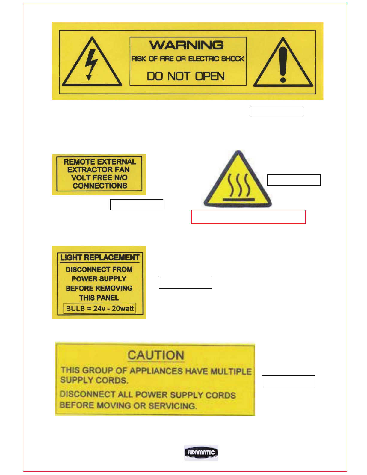
M257-20-01300
M247-20-01300
M257-20-0010
LABEL TO WARN OF HOT SURFACES
FG257 MODULAR DECK 02/07 RAC
M257-20-00200
M247-20-01400
51
Page 53
FG257 MODULAR DECK 02/07 RAC
52
Page 54
FG257 MODULAR DECK 02/07 RAC
53
 Loading...