

Page 1

037N
R
DENTAL CHAIR
INSTALLATION
OPERATION
and
INSTRUCTIONS
Page 2

Page 3

TABLE OF CONTENTS
Page
1.
OVERALL VIEW AND MAJOR COMPONENTS
2.
DIMENSIONS AND SPECIFICATIONS
3.
ELECTRICAL DIAGGRAM
4.
INSTALLATION PROCEDURES
5.
OPERATION PROCEDURES
............................................................................3
...................................................................4
..........................................................................5
6. ADJUSTMENT OF POSITIONING
7. CARE AND MAINTENANCE
............................................................................9
........................................................2
................................................................8
.......................................1
Intended Use of the Product
This product is intended for the exclusive use for diagnoses, treatments and relative
procedures of dentistry, and must be operated or handled by the qualified dentists or by
dental staffs under the supervision of the dentist.Such dentists or dental staffs should
instruct and/or assist the patients to approach to and leave from the product. Patients
should not be allowed to operate or handle the product unless he/she is so instructed.
Environmental Requirements
Operating Ambient Temperature 41°F ~ 104°F (5°C ~ 40°C)
Humidity 30% ~ 75%
Atmospherical Pressure 10.2psi ~ 15.4psi (700hpa ~ 1060hpa)
Storage Ambient Temperature 14°F ~ 122°F (-10°C ~ 50°C)
Humidity 10% ~ 80%
Atmospherical Pressure 8.7psi ~ 15.4psi (600hpa ~ 1060hpa)
Page 4
CAUTION
CAUTION
Classication
a. Protection against electric shock : Class I Equipment, Type B Applied Parts (Headrest,
Backrese and Seat cushions)
b. Protection against water ingress : Chair (IPX0)
c. Equipment not suitable for use in the presence of a flammable anesthetic mixture with air or with
oxygen or nitrous oxide.
d. Mode of operation : Non-continouous operation. ON time :3min. OFF time : 15 min
Symbol
Applied part complying with the specified requirements of IEC60601-1:2005 to provide
protection against electrical shock, particularly regarding allowable patient leakage current
and patient auxiliary current.
Caution, warning or note
• This chair is intended to be used for dental examination and treatment. Do not use this for any other
purpose than examination or treatment.
• Only a trained and qualifi ed personnel should operate this chair.
• Follow all the safety precautions and instructionsions to protect patients and operators.
• During treatment keep small children, except for a patient, away from the treatment area.
• Always keep an eye on the patient so he/she shall not touch the equipment.
• Keep patient’s and operator’s hands, fi ngers or parts of the body away from moving parts of the
equipment.
• In the case of defect, put a proper label on it. Call a technician of our authorized dealer.
• This product may be affected by sources that generate excessive electromagnetic waves.
• Do not install this equipment close to such devices such as elevators or communication equipment,
including cellular telephones.
• Electrosurgical knives may cause the chair to temporarily malfunction. If an electrosurgical knife is to be
used, turn off the main switch of the chair after the patient has been positioned.
• Take extreme care with patients that have a pacemaker. Prior to operation of the chair, ask patient to
verify whether they have a pacemaker. When operating chair, be certain patient displays no indication of
discomfort. Cease chair operation immediately and turn off main power switch if patient shows any sign
of being affected by chair operation.
• Do not position this equipment so that it is diffi cult to access the main power supply outlet that the power
plug of this chair is connected to.
The followings are prohibited.
• To modify this equipment.
• To use the equipment under any failure condition.
• To use the equipment without doing the daily and periodical check-up.
• To wipe the plastic covers with any disinfectant or detergent that contains organic solvent.
• To let a person on the chair who weighs over 300 lbs.
• To let two or more person on the chair.
Page 5
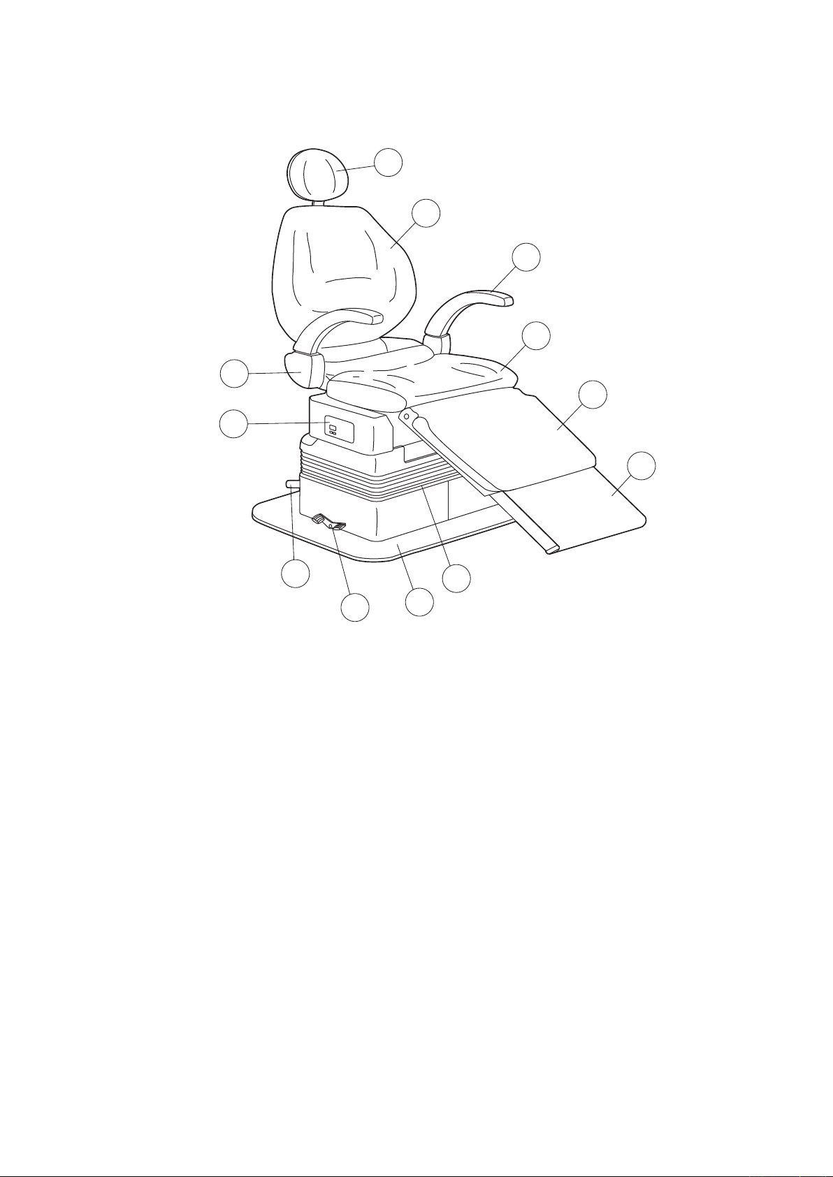
1. OVERALL VIEW AND MAJOR COMPONENTS
1
2
3
4
5
6
7
8
12
11
10
9
(1) ARTICULATING HEADREST (7) ARMREST BLOCK
(2) BACKREST (8) CHAIR PRESET PANEL
(3) ARMREST (9) BELLOWS
(4) SEAT (10) BASE PLATE
(5) LEGREST (11) ROTATION LOCK PEDAL
(6) RETRACTABLE FOOTREST (12) FOOT SWITCH (CHAIR)
Fig. 1-1 OVERALL VIEW
1
Page 6
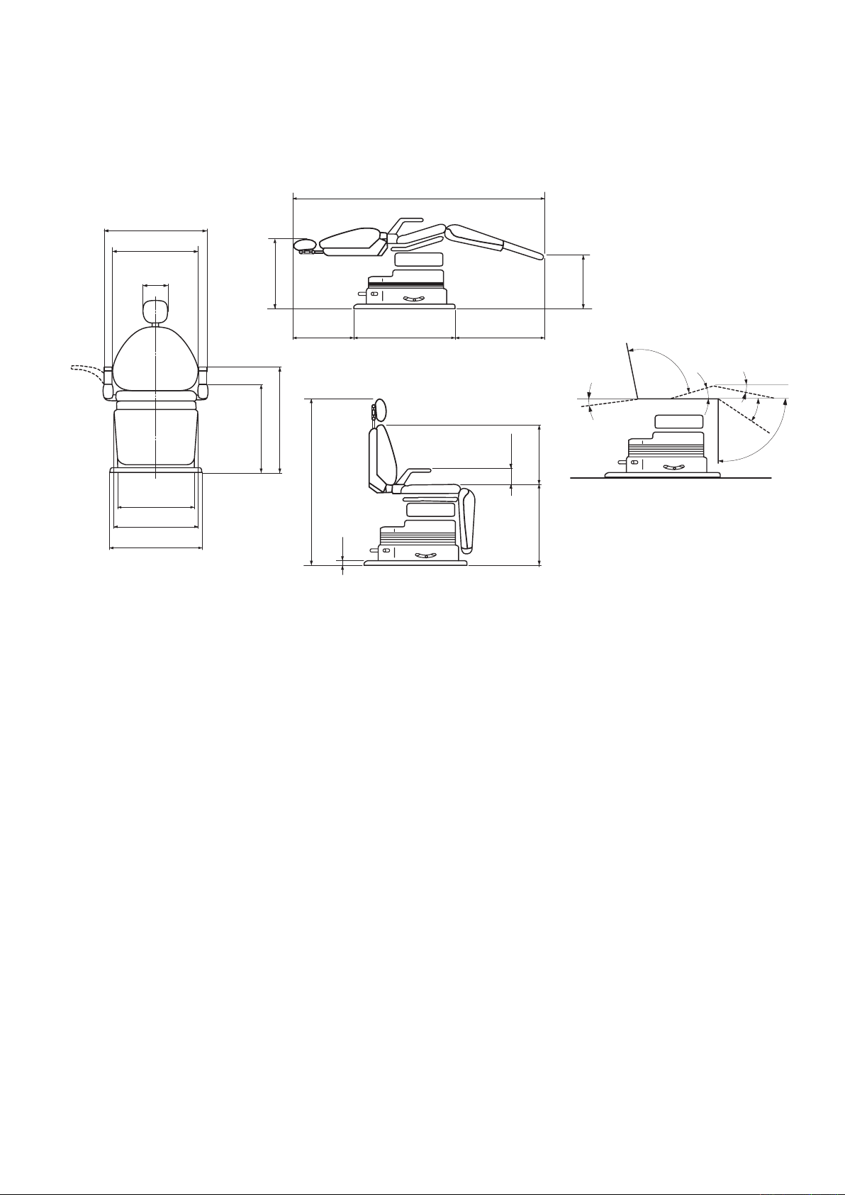
2. DIMENSIONS AND SPECIFICATIONS
17-7/8"
6-3/8"
18-1/2"
5/8"
43-3/8"
15-3/4"
16-3/8"
22" 25-5/8"19"
64-1/4"
20-15/32"
26-19/32"
8-9/32"(037)
8-21/32"(039)
19-11/16"
23-5/8"
22-21/32"
17-23/32"
19-11/16"
10
°
20
°
90
°
30
°
95
°
3
°
2-1. Dimensions
2-2. Specications
CHAIR WEIGHT ------------------------------------ 330 lbs
BASE DIMENSION --------------------------------- 22" x 22-5/8" x 5/8"
INITIAL HEIGHT ----------------------------------- 17-7/8"
SEAT ELEVATION STROKE --------------------- 10-1/4"
LEGREST EXTENSION --------------------------- 9-1/16"
ROTATION ------------------------------------------- 220 Degree Total (110 Degree. Left & Right)
MOTOR PUMP -------------------------------------- Type 5LP
PUMPING CAPACITY ----------------------------- 0.72 L/min. (0.19 gal/min)
HYDRAULIC FLUID ------------------------------- 900 cc (30 fl.oz)10W Non Detergent Hydraulic Oil
POWER REQUIRED -------------------------------- 115V 50 / 60Hz 5.7 / 3.6 A
2
Page 7
Pump Section
NMF6P
65432
1
31 2
CN8
B03B-XASK-1N-A
121110987654321
m12P
5
4
Fuse10A
VL2P
1
2
3 421
S12
IL-4P-S3EN2
(JAE)
4321
(AGEJ37**)
LED1
LED2
LED3
LED4
LED5
LED6
LED7
LED8
LED9
LED10
LED11
LED12
LED13
LED14
3
11V
9V
Capacitor Section (120V)
1G01AG**
S1-B(1-A)
IL-10P-S3EN2
(JAE)
10
987653 421
S7
IL-3P-S3EN2
(JAE)
S6
IL-3P-S3EN2
(JAE)
S5
IL-3P-S3EN2
(JAE)
CN12
IL-3P-S3EN2
(JAE)
321
S2-B(2-A)
IL-6P-S3EN2
(JAE)
S1-A(1-B)
IL-10P-S3EN2
(JAE)
S15
3P-SCN
S11
IL-3P-S3EN2
(JAE)
S10
IL-10P-S3EN2
(JAE)
VL4P
12345
6
2
1
VL8P
3
1
2
10
987653
42
1
123
123
10
987654321
Control PCB.(MCX2)
(AGDJ55**)
Relay PCB.(9RY)RY-2005
120V
【Remarks】
ConnectorSymbol
VL・・・VL Connector
M・・・CommercialConnector(AMP)
m・・・Mini Universal Connector(AMP)
NMF・・・NewMini Fit Connector(molex)
Plug
2 1
Motor
1
2
3
TSM-CBC-5LP-M1-E
Transformer
TK-120V-2H
SW3
SW1
LIM
NOL
EWS UOA S25 E53
(280°5K?)
LimitSW
STORE
EWS VDA S20 E53
M
321
123
321
123
Capacitor
45µF
1526374
8
123456789
10
132
6
4
321
4
231
2
4321
321
CN9
5566-10A
(MOLEX)
CN6
5566-08A
(MOLEX)
CN10
5566-06A
(MOLEX)
CN4
B02P-NV
CN3
B3P-VH
CN1
B2P-VH
CN2
B10B-XASK-1N-A
CN7
B04B-XASK-1N-A
CN11
5566-04A
(MOLEX)
CN5
B04P-NV
10
987653 421
1A047B**
Trunk Line for Motor/Capacitor
1G004V**
Transformer Section(120V)
1G01AG**
Motor Section (120V)
1A047A**
Trunk Line B for
Solenoid Valve
1A047D**
ANET12**
ANET14**
ANET13**
X-60060
ANET99**
Harness(A-4)PRO-M2
Signal Line for Relay
X-60080
Harness(A-6)PRO-M2
1G01BD**
S4-A(4-B)
IL-4P-S3EN2
(JAE)
1 2 3
4
S3-A(3-B)
IL-6P-S3EN2
(JAE)
SW2
MODE
JP1
1 2 3
1-2PinShortcircuit-NoUp&Down
2-3PinShortcircuit-WithUp&Down
LED1(Green)
LED2(Green)
LED3(:ML)
LED4(Orange)
1
2
5
1
4
1A047J**
m2P
1G01AJ**
Relay BOX Section(037)
120V・ETL
AR
P2 P1
LP
12345
6
123
4
654321 1 2 3 4 5 6
SV2
SV5
SV6
SV3
SV1
SV4
8765432
1
21
1G01AK**
Main Switch Section(120V)
1A0479**
1A0478**
Trunk Line for Relay
PCB/Transformer
321
VL6P VL3P
1 2
M2P
EWS UOA S25 E53
6
643211 2 3 4 5 6 5
S4-B(4-A)
IL-4P-S3EN2
(JAE)
1
2 4
3
6
65432
1
S2-A(2-B)
IL-6P-S3EN2
(JAE)
1 2 43 5 6 7 8 9
10
S8
IL-12P-S3EN2
(JAE)
11 12
65
S3-B(3-A)
IL-6P-S3EN2
(JAE)
4
3211 2
S9
IL-2P-
S3EN2
(JAE)
S13
IL-2P-S3EN2
(JAE)
2
1
1 2 3 4
S14
IL-4P-S3EN2
(JAE)
X-60970
Harness(A-11)PRO-M2
ANET04**
Stick Switch (100/240V)
m6P m6P
m6Pm6P
Potentiometer for Backrest
Potentiometer for Legrest
Potentiometer for Backrest
Potentiometer for Legrest
Brown
Red
Orange
Brown
Red
Orange
Potentiometer for Seat Lifting
Potentiometer for Seat Lifting
Brown
Red
Orange
Brown
Light Blue
Green/Yellow
Brown
Blue
Green/Yellow
Brown
Blue
Brown
Blue
Seat
Up
Down
Solenoid Valve Block(120V)
Raising
Lowering
Raising
Reclining
Legrest
Backrest
Yellow
Yellow
Yellow
Yellow
Yellow
Yellow
Yellow
Yellow
Yellow
Yellow
Yellow
Yellow
Trunk Line A for Solenoid
Valve
Brown
Blue
Green
Red
Orange
Gray
Purple
Yellow
White
Light Blue
Pink
Black
Brown
Blue
Trunk Line for Relay PCB.
Power Source
Cap
Black dot indicates
male pin side
Gray
White
Black
Purple
Blue
Red
Brown
Orange
Yellow
Green
Light Blue
Pink
Gray
White
Purple
Blue
Red
Brown
Orange
Yellow
Green
Black
Motor
Up
Down
Light Blue
Pink
Backrest Raising
Backrest Reclining
COM
Headrest Extention
Headrest Raising
Headrest Reclining
Headrest Lowering
Legrest Raising
Legrest Lowering
COM
Gray
Gray
Yellow
Yellow
Gray
Gray
Yellow
Yellow
Red
Brown
Blue
Blue
Trunk Line for Main
PCB. Power Source
Red
Brown
Orange
Yellow
Green
Red
Brown
Orange
Yellow
Green
Red
Brown
Orange
Yellow
Green
Red
Brown
Orange
Yellow
Green
Up
Down
Backrest
Backrest
Raising
Reclining
Up
Down
Backrest
Backrest
Raising
Reclining
Red
Brown
Orange
Yellow
Black
Gray
Green
Blue
Purple
Black
Red
Brown
Orange
Yellow
Green
Gray
Black
Purple
Blue
Red
Brown
Orange
Yellow
Green
Up
Down
Backrest Raising
Backrest Reclining
AR
P1
P2
LP
COM
Seat Section
Stick Switch
Up
Down
Backrest
Raising
Backrest
Reclining
Left
Center
Right
Up
Down
Backrest
Raising
Backrest
Reclining
Pump Section
Seat Section
Red
Red
Red
White/Brown
White
White
Yellow
Yellow
Yellow
Yellow
Yellow
Yellow
Red
White
Yellow
P1
P2
LP
AR
Control PCB. LED Information & Jumper Pin
The LED is off if a prohibit-all input is
present right after power is on.
Power LED. Indicates the power
supply to the p.c.board.
Limit status indicator. The LED is on while
the slide SW is at the limit position.
Serial transmission indicator. LED is on
flow of transmission current is detected.
PositionofJumperPin
(ChairUp&DownbyLPMode)
Green
Orange
Orange
Orange
Orange
Orange
Orange
Orange
Orange
Orange
Orange
Orange
Orange
Orange
Relay PCB. LED Information
RelayPCB.PowerOn
DuringChairUp
DuringChairDown
DuringBackrestRaising
DuringBackrestReclining
Not Available
Not Available
Not Available
Not Available
Not Available
During Legrest Raising
During Legrest Lowering
Not Available
Not Available
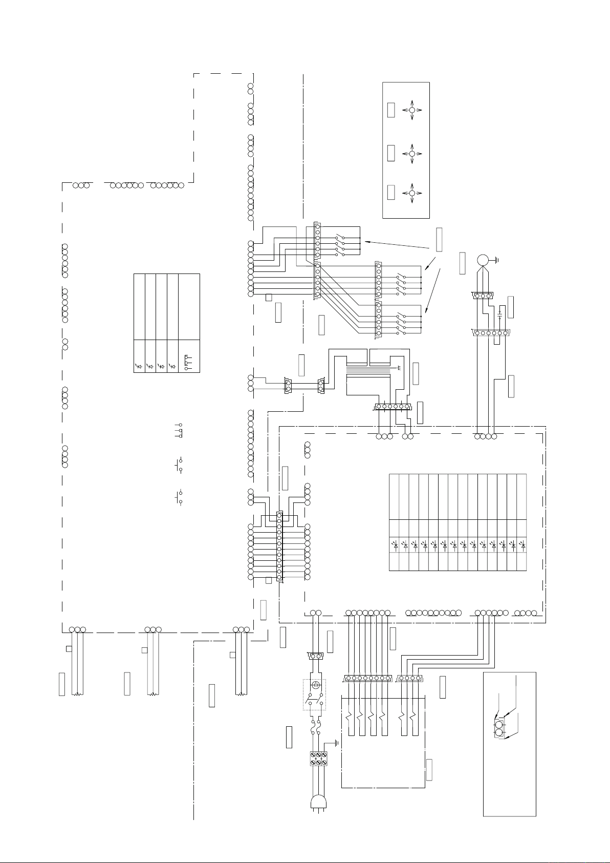
3. ELECTRICAL DIAGGRAM
3
Page 8
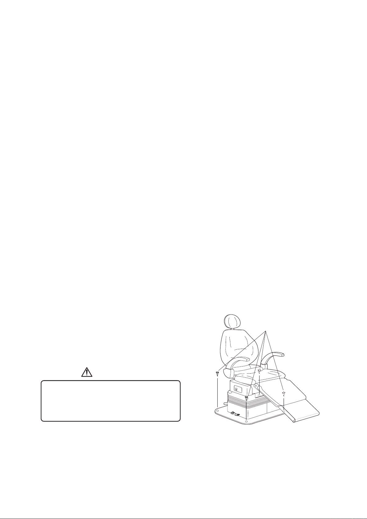
4. INSTALLATION PROCEDURES
Flat Head Wood Screws
CAUTION
1) Place chair crate just behind the planned location for the chair.
2) Open the crate and remove all packing materials.
(Do not use sharp instrument that can damage upholstery.)
Slide the chair off palette into the place.
DO NOT LIFT THE CHAIR BY ARMRESTS OR BACKREST.
3) Once the chair is located, but BEFORE PLUGGING INTO POWER, do the followings ;
(1) Remove red bolt with a caution tag located on chair seat-plate.
(2) Grasping red tag on bellows, pull out rubber plug of oil reservoir.
(3) Save above red bolt and rubber plug in case the chair is ever reshipped in the future.
4) Remove 3 nuts and washers under the seat.
Attach the seat on seat-plate and fix it by screwing the nuts and washers from
underneath the seat-plate.
5) Attach bellows to bellows support.
(1) Loosen and remove 4 Phillips screws on bellows support-rear, then remove the bellows
support-rear from the chair.
(2) Hang the top plate of bellows on the edge of bellows support-front, and hang the
top-rear plate of bellows on the edge of bellows support-rear.
(3) Reattach bellows support-rear with hanging bellows on to the chair by screwing 4
Phillips screws.
6) Unpack the small carton containing accessories. Check following items in it.
Headrest Assembly ......................................1 pce.
Flat Head Wood Screw (Pie.4.8 - 40) .......... 4 pcs.
Anchor Plug (7 x 30) .................................... 4 pcs.
For an 037N chair, slide headrest into slide mount on top of backrest.
7) Fixing the chair on the floor
Fix the chair base on the floor with bolts.
Chair base fixing points are shown in figure 3-1.
In case of wood floor, fix the chair base
with attached flat head wood screws.
In case of concrete floor, fix the chair base
with attached anchor plug and flat head wood screws.
Chair must be fixed to the floor with bolts
to prevent from falling down.
When fixing chair to the floor, be careful not
to damage pipings under the floor.
AFTER INSTALLATION
Once the chair is installed according to above steps, check the all chair function following
the operation procedures in this booklet.
Fig. 4-1 Fixing chair on the oor
4
Page 9
5. OPERATION PROCEDURES
2
1
3
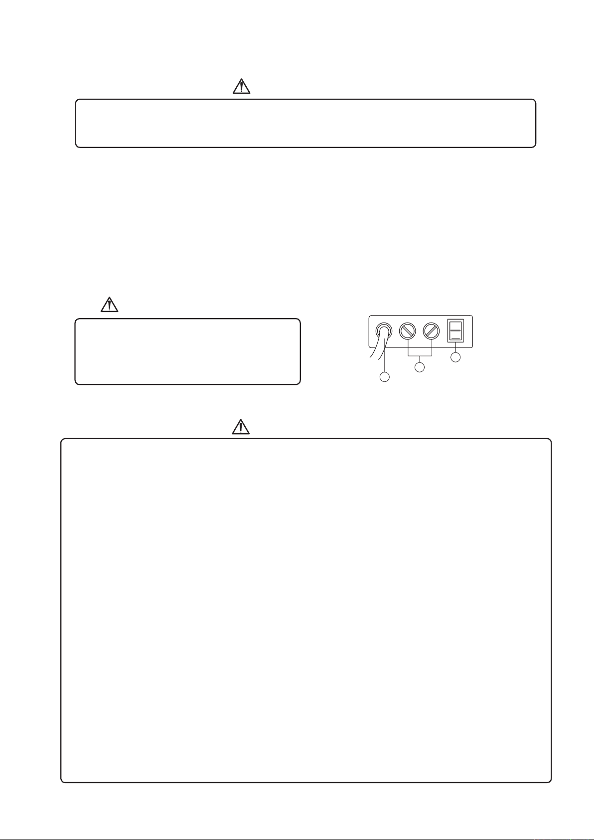
Main Power Switch
Fuse (6.3A)
Power Cord
CAUTION
CAUTION
CAUTION
To avoid the risk of electrick shock, this equipment must pnly be connected ato a supply mains
with protective earth. Grounding reliability can only archieved when the equipment is connrcted
to a equivalent receptacle marked HOSPITAL ONLY or HOSPITAL GRADE.
The Belmont 037N chair was designed for maximum simplicity of operation. However, taking
a few moments to familiarise yourself with the operation of the chair will make it's operation comfortable
and simple for you and your patients.
5-1. Main Power Switch
1) Plug the chair into an appropriate electric power source.
2) Turn on the Main Switch located on left side of Pump Cover. (See Fig. 4-1.)
Operate the Main Power Switch by hand only.
Turn off the main switch after daily operation.
Do not touch any switch with a wet hand,
as it might cause electric shork.
Fig. 5-1 Main Power Switch
Before use
• Check connection of swtiches and make sure that the device functions properly.
• Make sure that grounding wire is connected.
• Make sure that cables are properly and perfectly connected.
•
Be careful when you use the equipment combined with another, as it may lead to inadequate decision or danger.
Patient Entry
• Do not operate the chair until patient is fully seated. Patient head, back and feet must be in full contact
with seat cushions. Patient hands must be placed on top of forward facing armrests or on their lap. All
patients are at risk of potential injury if these precautions are not followed.
• Do not allow patient to sit on the hearest, armrest or on the backrest. Do not give too much load
on the chair cushions. Failure to do so might lead to malfunction or an accident, such as fall from the
chair or break of the device
During use
• Do not use the chair longer than required for examination or treatment.
• Always watch the patient and the equipment to make sure nothing is wrong.
• If anything wrong is observed with the equipment or the patient, take a proper action, such as stopping
the use of equipment as well as keeping the patient in safe.
• Keep an eye on the patient not to touch the equipment.
• Do not touch the patient and the fuse holder simultaneously.
After use
• Turn off the swtich and pull of the power supply plug.
• Clean the equipment and get it ready for use.
5
Page 10
5-2. Controls
Chair Functions
Preset / Auto-Return
Neutral
Lock
Rotation Lock Pedal
Chair Functions
Rotation Lock Pedal
RAISE CHAIR
LOWER CHAIR
RAISE
BACKREST
RECLINE
BACKREST
Chair Manual Controls
Chair Functions
Preset / Auto-Return
Neutral
Lock
Rotation Lock Pedal
RAISE CHAIR
LOWER CHAIR
RAISE
BACKREST
RECLINE
BACKREST
Chair Manual Controls
Preset / Auto-Return
3 (L P)
0
(AUTO-RETURN)
1
(PRESET)
2
(PRESET)
Neutral
Lock
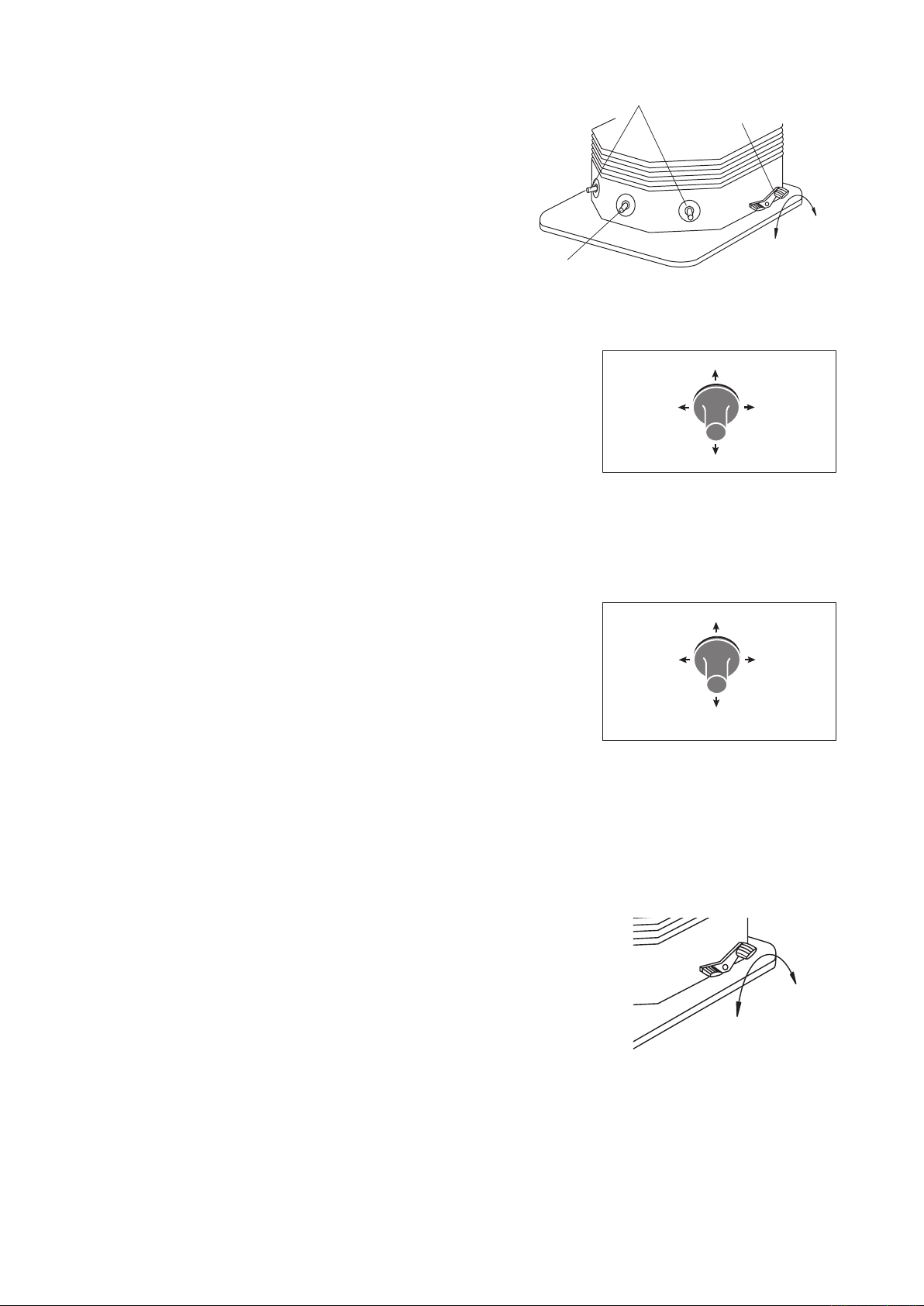
Basic Control Function (FIG.5-2)
•
Chair manual control functions are duplicated on
both sides of the pump cover.
•
Chair auto control functions are equipped on rear
side of the pump cover.
•
Chair rotation function are equipped on right side of
the pump cover.
1) Chair Manual Controls (See Fig. 5-3.)
(1) Seat Height Control
To raise : Move either side mounted foot switch up.
To lower : Move either side mounted foot switch down.
(2) Backrest Control
To raise : Move either side mounted switch right.
To reclining : Move either side mounted switch left.
Fig. 5-2 Control Switch Location
Fig. 5-3 Chair Manual Control
2) Chair Auto-mode Controls (See Fig. 5-4.)
(1) Preset Mode Controls(1.2.3)
037N chair has two preset positions and last position
memory. To place thechair in each position with
footrest extension. Momentarily move the foot switch
located on rear side of the pump cover.
1 (Preset 1) : Move rear mounted switch right.
2 (Preset 2)
3 (LP)
(2) Auto-return Control (0)
To return the chair to the patient entry position
(fully lowered with the footrest retracted),
Momentarily move rear mounted foot switch down.
3) Chair Rotation (See Fig.5-5)
Release rotation lock by pressing "N" footpad and lock chair in
desired position by pressing "L" footpad.
:
Move rear mounted switch left.
: Move rear mounted switch up.
Fig. 5-4 Chair Auto-mode Control
Fig. 5-5 Rotation Lock Pedal
6
Page 11
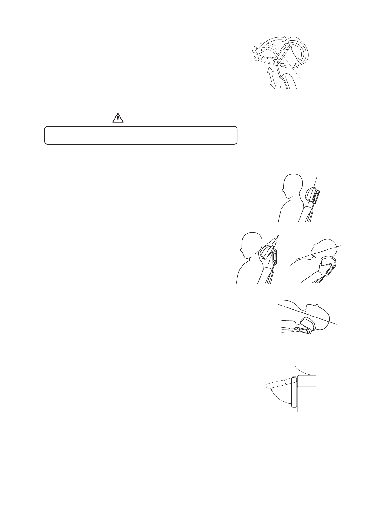
5-3. Headrest Adjustment (See Fig. 5-6)
CAUTION
Headrest Releas
e
Leve
r
(1) Height Adjustment
Press down or pull up the headrest for height adjustment.
(2) Angle Adjustment
Grab the headrest release lever on headrest mechanism
and move to desired position.
Take care not to pintch the fingers with the headrest mechanism.
5-4. Positioning of Headrest (See Fig. 5-7)
(1) Seat patient upright and all of the way back on the chair.
(2) Position the bottom of the headrest cushion so it is even
with the occipital of the patient’s head.
Fig. 5-6 Headrest Adjustment
Viewing the lower arch
(See Fig. 5-7)
(1) Using the latch release button (white), pivot the headrest
cushion halfway toward the patient’s head.
(2) Have the patient lean back on the headrest.
(3) Using the chair controls, place the patient in the desired
operating position.
Viewing the upper arch
(See Fig. 5-7)
(1) Lower the backrest and raise the base of the chair.
(2) Slide the headrest in.
(3) Support the patients head/headrest cushion while pressing
latch release button.
(4) Tilt the headrest cushion until the desired upper arch
position is obtained.
5-5. Armrest Rotation (See Fig. 5-8)
Either armrest can be rotated outward by pulling.
Fig. 5-7 Positioning of Headrest
5-6. Safety Stop
Automatic travel in all automatic mode can be instantly cancelled at any time by momentarily pressing
any control switch.
Fig. 5-8 Armrest Rotation
7
Page 12
MODE
STORE
6. ADJUSTMENT OF POSITIONING
3 (L P)
0
(AUTO-RETURN)
1
(PRESET)
2
(PRESET)
RAISE CHAIR
LOWER CHAIR
RAISE
BACKREST
RECLINE
BACKREST
RAISE CHAIR
LOWER CHAIR
RAISE
BACKREST
RECLINE
BACKREST
3 (L P)
1
(PRESET)
2
(PRESET)
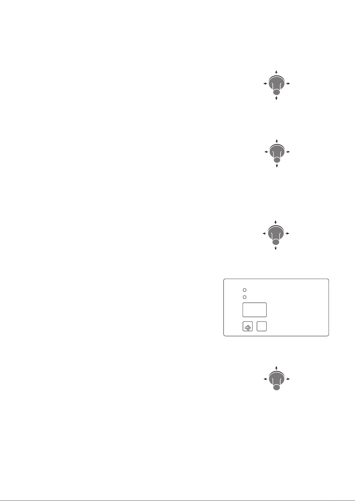
6-1. Auto Return (AR) , Preset (1.2) , and Rinsing Position (LP) Setup (Fig.6-1)
There are two different setup procedures but the results are the same.
1) Setup Procedure 1.
(1) Move the chair to desired position by manual control
switches.(Fig.6-1)
(Also, move the legrest to the desires extension or
retraction limit position)
(2) Move the stick switch (0 or 1 or 2 or 3) for that position
until the beeper sounds (about 5 seconds) to complete
the procedure.(Fig.6-2)
0 : Auto return
1 : Preset-1
2 : Preset-2
3 : (LP) Rinsing position as the last position
Fig. 6-1 Stick switch (Manual)
Fig. 6-2 Stick switch (Auto-mode)
2) Setup Procedure 2.
(1) Move the chair to desired position by manual
control switches.(Fig.6-1)
(Also, move the legrest to the
desires extension or retraction limit position)
(2) Press and hold down the “Store” SW (about 2
seconds)(Fig.6-3).
After the initial beeper sound, the beeper keeps on
sounding once at the “pip, pip”
(ten times at one second intervals).
(3) Press the stick SW (1 or 2 or 3) for that position to
complete the procedure.(Fig.6-4)
If the step 3 does not take place within 10 seconds,
the procedure is terminated.
(Setup of the Auto return position is not available.)
(4) To exit the procedure during the step 2, press the
“Store” SW once again.
Fig. 6-1 Stick switch (Manual)
Fig.6-3 Chair Preset Panel
Fig. 6-4 Stick switch (Auto-mode)
8
Page 13
7. CARE AND MAINTENANCE
CAUTION
CAUTION
7-1. Cleaning and disinfection
Do not spray liquids directly onto chair surfaces.
In order to prevent damage to electrical components and systems, do not apply excess cleaning
solution onto chair surfaces.
Routine Care
Clean plastic and upholstery surfaces iegularly using a mild soap and water solution.
When cleaning, use a dampened cloth only, as excess cleaning solution can flow into the chair and cause permanent
damage to electrical components.
Barrier Technique
Use of disposable barrier products should be the first choice for the protection of dental equipment. Disinfectants
leave behind a surface residue that accumulates over time and eventually damages equipment and upholstery
surfaces.
Chemical Disinfection
If a chemical disinfectant is to be used on chair or upholstery surfaces, contact the manufacturer of the disinfectant
prior to use.
Obtain verification from the disinfectant manufacturer that their product will not damage the chair or upholstery
surfaces.
Unacceptable Disinfectants
The following chemicals may damage equipment and upholstery:
* Alcohol based solutions
* Bleach
* Phenol / Alcohol combinations
* Foam spray products
* Benzalconium chloride solutions
Use with Caution
* Water based phenolic disinfectants, following manufacturer’s exact instructions for use.
Warranty does not cover damage to equipment and upholstery caused by disinfectant solutions.
7-2 Storage and working lifetime
7-2-1 Storage
1. Keep the equipment away from water.
2. Keep in a circumstances safe from influance by temparature, humidity, wind, sun light, air containig salts
and minerals.
3. Care about stability such as inclination, vibration and impact, including handling and transportation.
4. Do not keep the equipment in a place where chemicals are or where gas is emitted.
7-2-2 Lifetime
Provided that the recommended and authorized care and maintenance are correctly performed, the
working lifetime of this equipment is 10 years from the date of initial shipment from the manufacturer.
9
Page 14

No. Item
(Frequency)
How to check and diagnose Infl uence of not doing
check-up
Actions when any incompliance is found
1 Safety functions
(Daily. Before
opening offi ce)
During pre-set movement or
auto-return movement, press any
key for chair operationnand the
chair should automatically stop.
Injury caused by movement of the chair during
treatment or pinching with
chair and other equipment
or furniture.
Call to a technician of our
authorized dealer.
2 Function of each
switch
(Daily. Before
opening offi ce)
Each switch for chair operation
should work correctly.
Defect of movement may
cause an accident.
Call to a technician of our
authorized dealer.
3 Wiping off water
(Daily. Before
closing offi ce)
Make sure that no water is left
that were spilt during treatment.
Water will caus rust Wipe off water with a soft
and dry cloth.
4 Stain removal of
external parts
(Daily. Before
closing offi ce)
Visually make sure that no dust,
chemical or other material is left
on the chair.
Such chemicals will cause
discoloration, deterioration and break of the
plastics.
Thoroughly clean the
chair following the
cleaning instruction in
this book, regardless the
result of this check-up.
For tough stains, use mild
detergent solvency.
5 Main power
switch
(Daily. Before
closing offi ce)
Make sure that the main power
switch is off
Accident or defect of the
equipment
In the case the main
power cannot be turned
off, Call to a technician of
our authorized dealer.
6 Moving parts
(Weekly)
Make sure that the chair does not
make any abnormal noise during
automatic movement
Accidend or defect of the
equipment
Call to a technician of our
authorized dealer.
7 Oil leakage
(Weekly)
Make sure that there is no hydraulic oil on the fl oor or chair
base leaking from the cylinder.
Defect of the equipment Call to a technician of our
authorized dealer.
8 Power supply
cable
(Monthly)
Power supply cable should not
be abnormally bent, pintched or
damaged, and the plug should
be fi rmly inserted to the power
outlet and not covered with dust.
Accident or defect of the
equipment
Clean and rearrange the
cable. For replacement,
call to a technician of our
authorized dealer.
7-3. Daily Check-up of functions by the end user
The end-user is responsible for daily check-up of the equipment. In the case end user does not do this, it is
allowed that you outsource it to a technician authorized by us.
In order to assure safety use of this equipment, please carry out the following check-up in a frequency as
indicated below.
10
Page 15
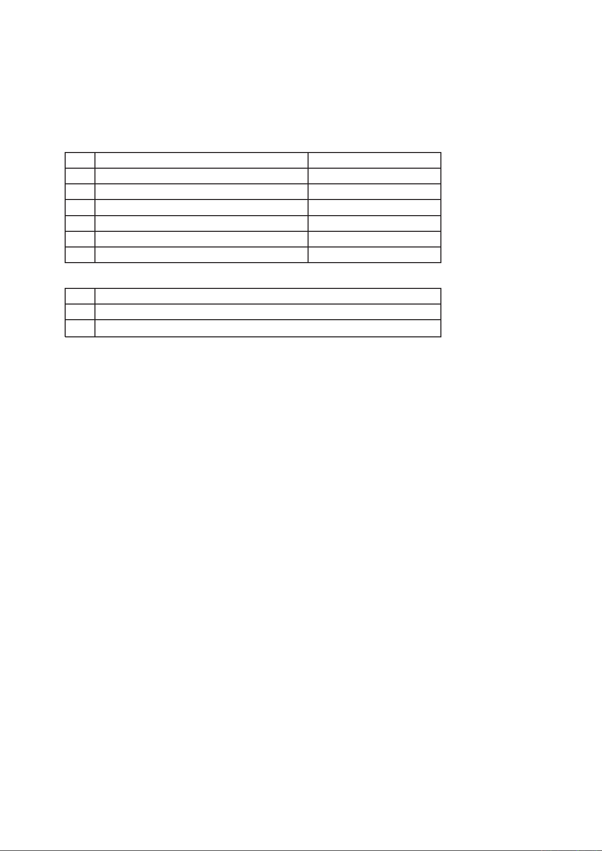
Parts and components that require periodical check-up
emitefiL dradnatSnoitpircseD straP.oN
sraey 2msinahceM tserdaeH1
2 Electric wiring of moving parts 2 years
3 Swithes for operating equipment 2 years
Transformer 3 years4
sraey 3sBCP lortnoC5
6 Hydraulic cylinder and related parts 5 years
Consumables
No. Parts Description
1 Power supply cord
2 Cusions and Upholsteries
7-4. Guideline for Periodical Check-up
•
Some parts and components of the products are degraded or deteriorated depending on the frequency of use,
so yearly check-up and maintenance, as well as replacement of comsumable parts, are required.
• For check-up and repair, call a technician of our authorized dealer.
7-5 Disposal
• This is not an infecious device, but prior to disposal make sure that no parts of the device is infected.
• Follow the federal, state and local regulations for disposal.
11
Page 16

R
NOTE
This equipment should installed by an professional technician(s) of our company or a company authorized by us.
Follow the installation manual enclosed with this manual for details of installation.
Company or person authorized to install this equipment
Name :
Address :
BELMONT EQUIPMENT, Division of Takara Belmont, USA, Inc.
101 Belmont Drive Somerset, New Jersey 08873 U.S.A. TEL.:(732) 469-5000 / (800) 223-1192 Fax.:(732)526-6322 / (800) 280-7504
www.belmontequip.com
TAKARA CO, CANADA LTD.
2076 S. Sheridan Way, Mississauga, Ont., L5J2M4, Can. TEL.:(905) 822-2755 Fax.:(905)822-6203
www.takarabelmont.ca
TAKARA BELMONT CORPORATION (Manufacturer)
1-1, 2-Chome, Higashi-shinsaibashi,Chuo-ku,Osaka,Japan TEL.: 81-6-6213-5945 FAX.: 81-6-6212-3680
Printed in Japan,1109
Book No.
 Loading...