

Page 1
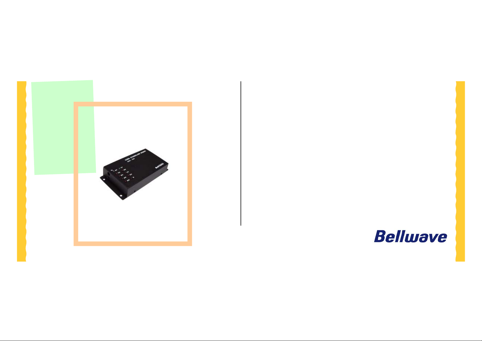
User’s Manual
CDMA STANDALONE MODEM
BSM-856
-1-
User’s Manual (preliminary)
Page 2

3.3.3 Basic AT Parameters..............................................................................11
목차
3.3.4 Basic S Registers....................................................................................13
1 개요 .........................................................................................................................4
1.1 특징 .................................................................................................................4
2 MODEM SPECIFICATION................................................................................. 5
2.1 M
2.2 E
2.3 E
2.4 C
ECHANICAL SPECIFICATION ...........................................................................5
NVIRONMENTAL SPECIFICATIONS ...................................................................6
LECTRICAL SPECIFICATIONS...........................................................................6
ONNECTOR VENDOR....................................................................................... 7
3 MODEM INTERFACE.........................................................................................7
3.1 P
3.2 P
3.3 LED
IN ARRAY........................................................................................................7
OWER SUPPLY SIGNALS.................................................................................. 8
INDICATING.............................................................................................. 8
3.3.1 Basic AT Command..................................................................................8
3.3.2 Basic Result Codes.................................................................................10
3.4 V
ENDOR-SPECIFIC AT COMMANDS .................................................................15
3.4.1 Vendor-specific command by Qualcomm ...............................................15
4 APPLICATION EXAMPLES.............................................................................16
4.1 V
OICE CALL....................................................................................................16
4.2 SMS ...............................................................................................................18
5 DATA COMMUNICATION................................................................................19
5.1 표준
5.2 하이퍼터미널
5.2.1
5.2.2
5.3 M
5.4 내장
모뎀 만들기 ........................................................................................19
사용 ......................................................................................24
새로 만든 표준
직접 포트를 선택한 경우
TOM 접속...................................................................................................28
TCP/IP 사용하기.................................................................................29
19200
모뎀을 선택한 경우
..................................24
..................................................................25
-2-
User’s Manual (preliminary)
Page 3

Restricted Distribution: This document contains critical
information about Bellwave products and may not be distributed to
anyone without written permission of Bellwave Co., Ltd All data
and/or information contained in this document are proprietary and
confidential information of Bellwave Co., Ltd No part of this document
may be reproduced, in any form or by any means, without written
permission of Bellwave Co., Ltd
All Right Reserved, Copyright© Bellwave Co., Ltd 2005
-3-
User’s Manual (preliminary)
Page 4

1 개요
z Standard RS-232 Interface
z DM Port
BSM-856 외장형 모뎀은 M2M 비즈니스에 알맞도록 임의의 시스템에 부가적
시스템으로서 장착하여 해당 시스템이 CDMA 무선망에 접속하여 음성 및
데이터 통신 기능을 갖도록 하는 무선 단말장치입니다.
본 모뎀은 153.6kbps의 packet data 전송 속도를 지원하며, 퀄컴의 gpsOne 기
능을 이용하여 GPS을 이용한 위치추적 서비스 기능도 가능하여 원격감시,
제어, 검침. 텔레매틱스, 보안기기 등의 다양한 응용분야에 적용 할 수 있도
록
설계된 외장형 모뎀입니다.
1.1 특징
z gpsOne® Service
z Voice/DATA Service
z Analog Audio Interface
z SMS (Short Message Service)
z Standard & Extended AT Command Set
z Embedded TCP/IP Protocol St ack
z Buzzer Output
z Power On/Off Control
-4-
User’s Manual (preliminary)
Page 5
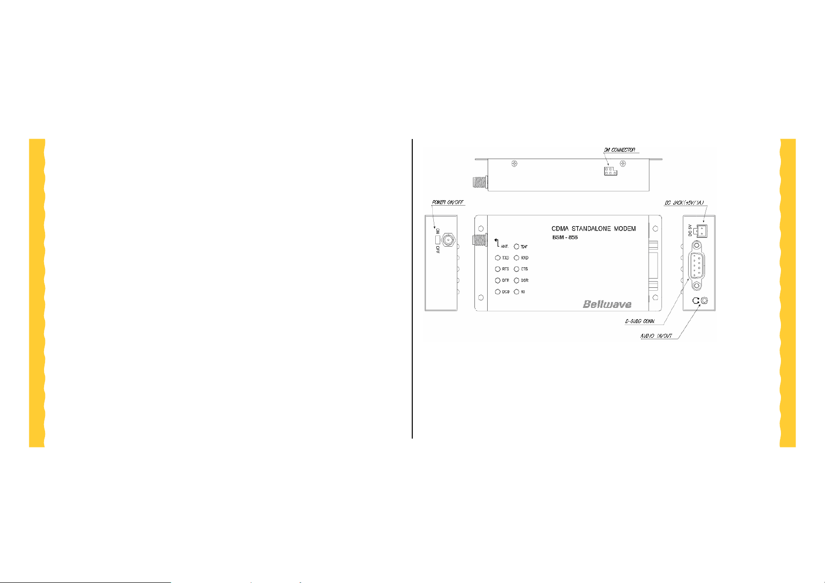
2 Modem Specification
2.1
Mechanical Specification
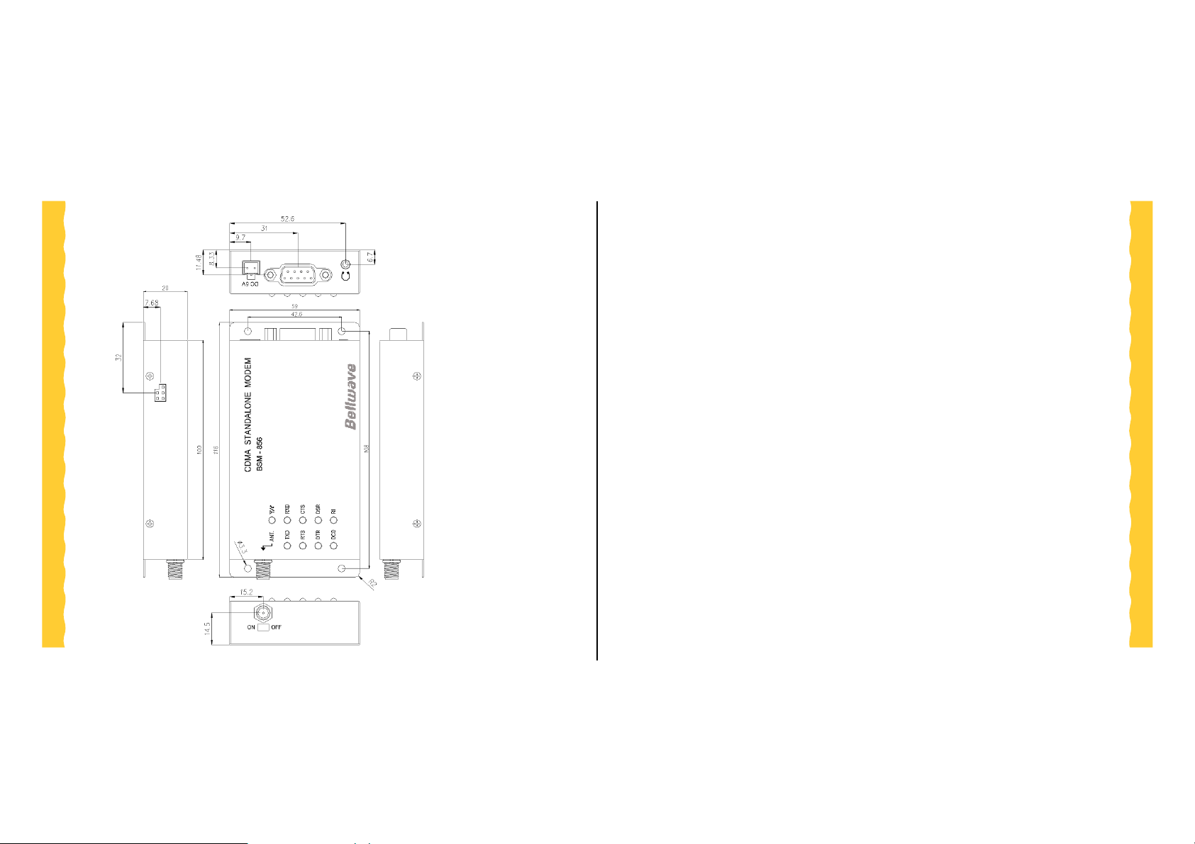
z Dimension : 116 x 59 x 20 (L x W x H)mm
z Weight : 145g
z Antenna connector : SMA type
z Mounting : 3.2mm 4 Holes
z Modem interface : D-SUB 9 connectors
-5-
User’s Manual (preliminary)
Page 6
2.2 Environmental Specifications
z Storage Temperature -30°C to +70°C
z Operating T emperat ure -20°C to +60°C
z Humidity (Operating) 95% (50°C) relative humidity (non-
condensing)
z Vibration (Operating) 5 Hz to 500 Hz sinusoidal, 1.5G
z Drop No damages after 60-inch drop over
concrete floor
2.3 Electrical Specifications
z Power input DC 5V
z Maximum current 1A
z Idle current 90~100mA
-6-
User’s Manual (preliminary)
Page 7
2.4 Connector V endor
3 Modem Interface
z Modem Interface Connector(30Pin)
Mating Connector Part No: TSH-115-01-F-DV-A-M-TR
(제조사: SAMTEC)
z Power Connector(2Pin)
- Mating Connector Part No: SMH250-2 (연호전자)
z Antenna Connector Standard SMA connector
z Mounting hole 3.2mm 4 positions (4 holes)
3.1
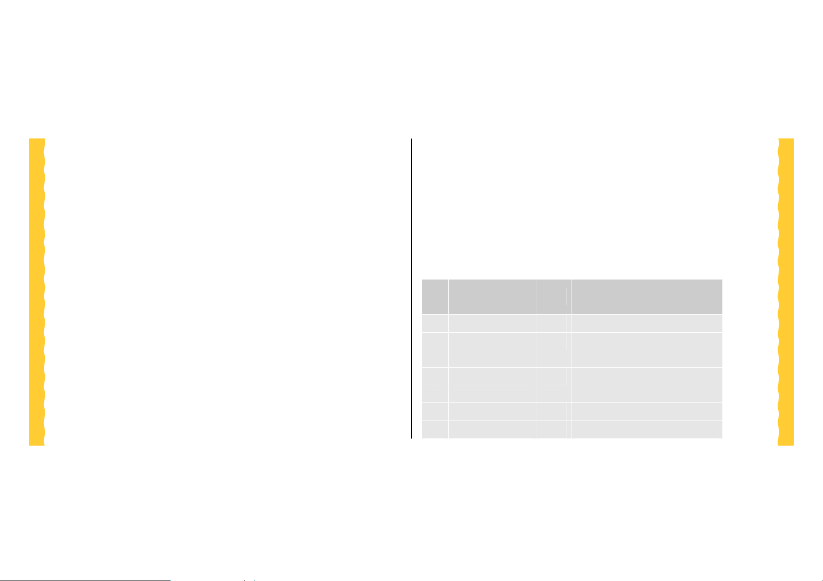
BSM-856은 외부 기기와 인터페이스를 하기 위하여 D-SUB 9 핀 커넥터를 제
공합니다.
Pin
NO.
Pin Array
Signal Name Type Description
1 DCD- O Data Carrier Detect
2 RXD O Receive data from the MODEM the
HOST
3 TXD I Transmit data from the HOST to the
MODEM
4 DTR- I Data Term inal Ready
5 GND GND Ground
-7-
User’s Manual (preliminary)
Page 8
6 DSR- O Data set Ready
7 RTS- I Request to send
8 CTS- O Clear to send
9 RI- O Ring Indication
I : Input O : Output
<표 3-1 Pin Descriptions>
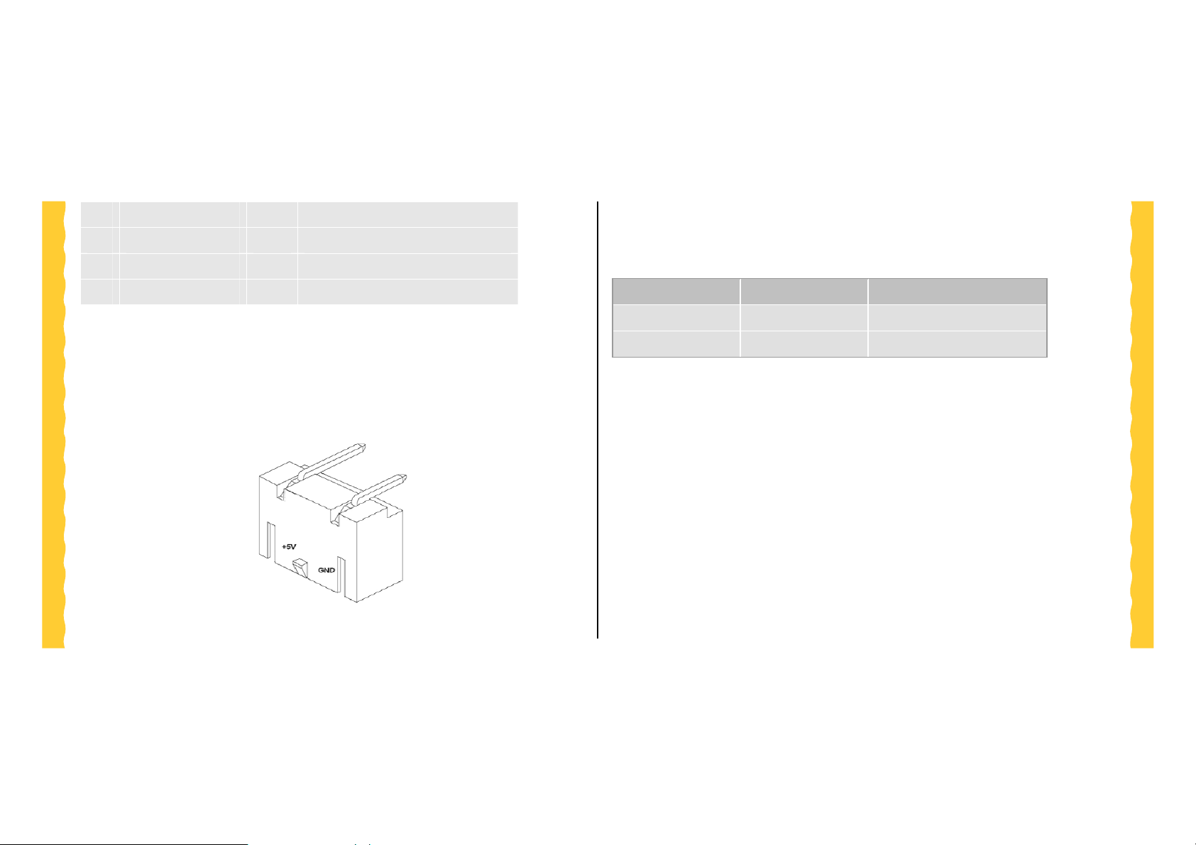
3.2 Power Supply Signals
<Figure 3.2-1 Power Connector>
3.3 LED Indicating
Mark Status Action
INRANGE Idle(In range) Blinking
INRANGE Line’s busy On
3.3.1 Basic A T Command
Table 2.1.1-1 specifies the Basic Action Commands to be supported for the CDMA data
services. Exceptions to EIA/TIA-602 are indicated in Table 2.1.1-1 by square brackets.
Default settings are shown in bold.
-8-
User’s Manual (preliminary)
Page 9

Command Description
A/ Re-execute previous command.
A Enter the online state. See service specific processing for further
details.
D<dial
string>
Causes the MT2 to transition from the command state to the online state.
The <dial string> is optional. For circuit switched data services, the
dial string may contain the following characters: Digits 0 to 9, *, #, A, B,
C, and D.
The dial string may contain the following dial modifiers:
T Tone dialing [ignore]
P Pulse dialing [ignore]
, Pause during dialing
W Wait for dial tone
@ Wait for quiet answer
! Hook flash
[$] Wait for billing tone (for credit-card calls)
; After dialing, the IWF enters the online command state and
maintains the connection
H0 Causes the MT2 to transition from onlin e command state to command
state. Use of the digit ‘0’ is optional (see EIA/TIA-602).
-9-
User’s Manual (preliminary)
Page 10

O0 Causes the MT2 to transition from onlin e command state to online state.
Use of the digit ‘0’ is optional (see EIA/TIA-602).
3.3.2 Basic Result Codes
Table 2.1.2-1 specifies the Basic Result Codes to be supported for the CDMA data
services. Exceptions to EIA/TIA-602 are indicated in Table 2.1.2-1 by square brackets.
Default settings are shown in bold.
The ERROR result code shall be returned for all commands, which do not comply with
the syntax rules of 5.1 of EIA/TIA-615, or Secti on 5 of EIA/ TI A- 6 02 .
Numeric Verbal Description
Async
& Fax
0 OK Command executed. R R R
1 CONNECT Entering online state. R R R
Packet
STU III
Data
2 RING
3
4 ERROR
6
7 BUSY
8
NO
CARRIER
NO
DIAL TONE
NO
ANSWER
Alerting signal received
R N/A N/A
from network.
Unable to activate the
R R N/A
service.
Command not recognized
R R R
or could not be executed.
No dial tone detected
R N/A N/A
within time-out period.
Reorder (Busy signal)
R R N/A
received.
Five seconds of silence
not detected after ring
R N/A N/A
back when @ dial
modifier is used.
-10-
User’s Manual (preliminary)
Page 11

3.3.3 Basic A T Parameters
Table 2.1.3-1 specifies the basic AT parameters to be supported for the CDMA data
services. Exceptions to EIA/TIA-602 are indicated in Table 2.1.3-1 by square brackets.
Default settings are shown in bold.
Parameter Description IS-707 req’t
E0
E1
L0
Do not echo commands in
command state or online
command state.
Echo commands in command
state or online command state.
Low speaker volume. Async: R,L
Async:R,M
Packet: O
Async:R,M
Packet: O
Packet: N/A
Implement
Status
Fully
Implemented
Fully
Implemented
Command accept
No action taken
L1
L2
L3
M0
M1
Q0
Q1
V0
Low speaker volume. Async: R,L
Packet: N/A
Med speaker volume. Async: R,L
Packet: N/A
High speaker volume. Async: R,L
Packet: N/A
Speaker off. Async: R,M
Packet: N/A
Speaker on until carrier reported
(support of this feature is
optional).
Return result codes. Async: R,M
Do not return result codes. Async: R,M
Display result codes as numbers. Async: R,M
Async: R,M
Packet: N/A
Packet: R
Packet: R
Packet: R
Command accept
No action taken
Command accept
No action taken
Command accept
No action taken
Command accept
No action taken
Command accept
No action taken
Fully
Implemented
Fully
Implemented
Fully
Implemented
-11-
User’s Manual (preliminary)
Page 12

V1
X1
X2
X3
Display result codes as words. Async: R,M
Packet: R
Enable additional result code
CONNECT <rate>.
Async: R,M
Packet: N/A
Disable dial tone and busy
detection.1
Enable additional result codes
CONNECT <rate> and NO
Async: R,M
Packet: N/A
DIALTONE. Disable busy
detection. Enable dial tone
detection.1
Enable additional result codes
CONNECT <rate> and BUSY.
Async: R,M
Packet: N/A
Enable busy detection. Disable
dial tone detection.1
Fully
Implemented
Fully
Implemented
Fully
Implemented
Fully
Implemented
X4
Z0
&C0
&C1
&D0
Enable additional result codes
CONNECT <rate>, BUSY and
Async: R,M
Packet: N/A
NO DIALTONE. Enable busy
and dial tone detection.1
Reset to default configuration. Async: R,L
Packet: R
Circuit 109 (CF) always ON. Async: R,L
Packet: R
Circuit 109 (CF) ON in
accordance with the specified
Async: R,L
Packet: R
service.
Ignore circuit 108/2 (CD). Asyn c: R,L
Packet: R
Fully
Implemented
Fully
Implemented
Fully
Implemented
Fully
Implemented
Fully
Implemented
-12-
User’s Manual (preliminary)
Page 13

[&D1]
&D2
T
P
&Fn
Enter online command state
following ON-to-OFF transition
of circuit 108/2. See service
specific AT command processing
for service state transitions.
Enter command state following
On to Off transition of circuit
108/2. See service specific AT
command processing for service
state processing requirements.
Select tone dialing. Async: R,M
Select pulse dialing. Async: R,M
Set to factory-defined
configuration “n.” Effect is
implementation dependent.
Async: R,L
Packet: R
Async: R,L
Packet: R
Packet: N/A
Packet: N/A
Async: R,M
Packet: O
Fully
Implemented
Fully
Implemented
Normal Dialing
Normal Dialing
Fully
Implemented
Note. For Async data or fax settings, the dial tone detection settings do not apply.
Legend: R=Required, O=Optional, M=Remote AT Command, L=Local AT Command.
3.3.4 Basic S Registers
Table 2.1.4-1 specifies the basic S Registers to be supported for the CDMA data
services. Exceptions to EIA/TIA-602 are indicated in Table 2.1.4-1 by square brackets.
Default settings are shown in bold.
Reg
Value Description IS-707 req’t Implement
S0
0
[1 to
255]
Disable automatic answering.
[Enable automatic answering
after
(Value - 1) 6 seconds.]
Async:R,L
Packet: N/A
status
Fully
Implemented
-13-
User’s Manual (preliminary)
Page 14

13
Carriage Return character. Async:R,M
S3
10
Line Feed character. Async:R,M
S4
8
Backspace character. Async:R,M
S5
2 to 10 2 Pause before blind dialing. Async:R,M
S6
S7
1 to
255
Number of seconds to establish
end-to-end data connection.
[50]
S8
[S9]
0 to
255
2
0 to
255
Number of seconds to pause
when “,” is encountered in dial
string.
Carrier detect threshold in
increments of 0.1 seconds.
Packet: O
Packet: O
Packet: O
Packet: N/A
Async:R,M
Packet: O
Async:R,M
Packet: N/A
Async:R,M
Packet: N/A
Fully
Implemented
Fully
Implemented
Fully
Implemented
Fully
Implemented
Fully
Implemented
Fully
Implemented
Fully
Implemented
S10
1 to
254
Number of tenths of a second
from carrier loss to disconnect.
Async:R,M
Packet: N/A
[14]
[255] [Disable carrier detect.]
50-255
DTMF tone duration and spacing
Async:R,M
[S11]
95
in milliseconds.
Packet: N/A
Fully
Implemented
Fully
Implemented
6
-14-
User’s Manual (preliminary)
Page 15

3.4 Vendor -specific A T Commands
3.4.1 Vendor-specific command by Qualcomm
Command Description Operation
$QCDMG
&V
&C0
&C1
&C2
Transition to Diagnostics
Monitor (DM) operation
Dump Configuration
parameters
Carrier Detect Pin
behavior
This command will return “OK” and then
transition the phone serial port to DM
Mode. DM Mode runs at 38.4Kbps and
uses a proprietary half-duplex protocol.
This command will dump the status of all
AT Parameters. This includes the single
letter parameters not otherwise readable,
but does not include the +QC parameters
C0: leave Carrier Detect pin Asserted at
all times.
C1: Carrier Detect pin Asserted when
$QCSO=
$QCCAV
$QCVAD=
Set Data Service Option
number set; saves to nonvolatile memory
Answer incoming voice
call
Pre-arrangement setting;
respond to Page message
that has a Voice service
option with Page response
that has a Data service
option
mobile is on the Traffic Channel,
otherwise de-asserted
C2: Carrier Detect Asserted at all times
but will wink when the Traffic Channel
drops.
0:= pre-707 SO numbers
1:= proprietary SO numbers
2:= IS-707 SO numbers
This command provides a means to
answer an incoming voice call via an AT
Command.
0:=Off
1:=Fax for next call
2:=Fax for all calls
3:=Async for next call
4:=Async for all calls
-15-
User’s Manual (preliminary)
Page 16

$QCDMR=
$QCMDR=
&D0
&D1
&D2
Set DM baud rate
Set Medium Data
Rate(MDR) setting
DTR Pin setting D0: Ignore DTR
19200,38400,57600,115200
Valid values are 0-2
0:=MDR Service Only.
1:=MDR Service if available.
2:=LSPD Only.
3:=CDMA 1x Service if available.
D1: Answer Packet Call when DTR is
asserted, Drop Traffic Channel on DTR
de-asserts.
D2: same as D1
4 Application Examples
4.1
Voice Call
초기설정
Æ
TE2
TE2
TE2
TE2
전화번호 확인
TE2
TE2
TE2
Å
Æ
Å
Æ
Å
Å
MT2
MT2
MT2
MT2
MT2
MT2
MT2
ATZ
OK
AT$MODE=2
OK
AT$PHONENUM?
01094356453,1094356453
OK↵
모듈 초기화 명령
결과
Notification을 UART1으로 설정
결과
전화번호 확인 명령
MDN,MSIN
결과
-16-
User’s Manual (preliminary)
Page 17

전화 걸기
Æ
TE2
TE2
TE2
TE2
Å
Å
Å
MT2
AT$KEY=021234569S
MT2
OK
MT2
$017:0234608860
MT2
CONNECT
전화 끊기(상대방이 끊은 경우)
Å
TE2
MT2
NO CARRIER
전화끊기(자기가 끊은 경우)
Æ
TE2
TE2
TE2
Å
Å
MT2
MT2
MT2
AT$KEYE
OK
NO CARRIER
전화번호 02-123-4569으로 전화 걸
기
결과
음성호의 통화채널 열림 알림
연결
호종료
전화 끊기 명령
결과
호종료
전화가 걸려온 경우
Å
TE2
TE2
TE2
Å
Å
MT2
MT2
MT2
전화 받기
Æ
TE2
TE2
TE2
Å
Å
MT2
MT2
MT2
$024
$002:0202785101
RING
AT$KEYS
OK
CONNECT
음성호 착신 알림
상대방(02-0278-5101) 발신자표시 알림
RING
전화 받기 명령
결과
연결
-17-
User’s Manual (preliminary)
Page 18

4.2 SMS
SMS 전송
TE2
TE2
TE2
SMS 수신
TE2
TE2
Æ
Å
Å
Æ
Å
MT2
MT2
MT2
MT2
MT2
AT$SMSMO=010
94356453,0101234
569,4098,,,,48656C
6C6F
OK
$006
$008:0
AT$SMSMT=1?
송신자(010-123-4569)가 SMS로
“Hello” 문자를 상대방(010-9435-
6453)으로 문자메시지(4098)를 전
송
(“Hello” Æ HEX값
“48656C6C6F”)
결과
SMS 전송 성공
SMS 문자 메시지 수신 알림
수신 메시지 확인
TE2
TE2
TE2
Å
Å
Å
MT2
MT2
MT2
20041018154944,0
101234569,4098,0,
0,48656C6C6F
OK
AT$SMSMT=1?
ERROR
2004년10월18일15시49분44초에
0101234569에서 보낸 문자메시지
(4098) “Hello” (“Hello” Æ HEX값
“48656C6C6F”)
결과
수신 메시지 확인
더 이상 메시지 없음
-18-
User’s Manual (preliminary)
Page 19
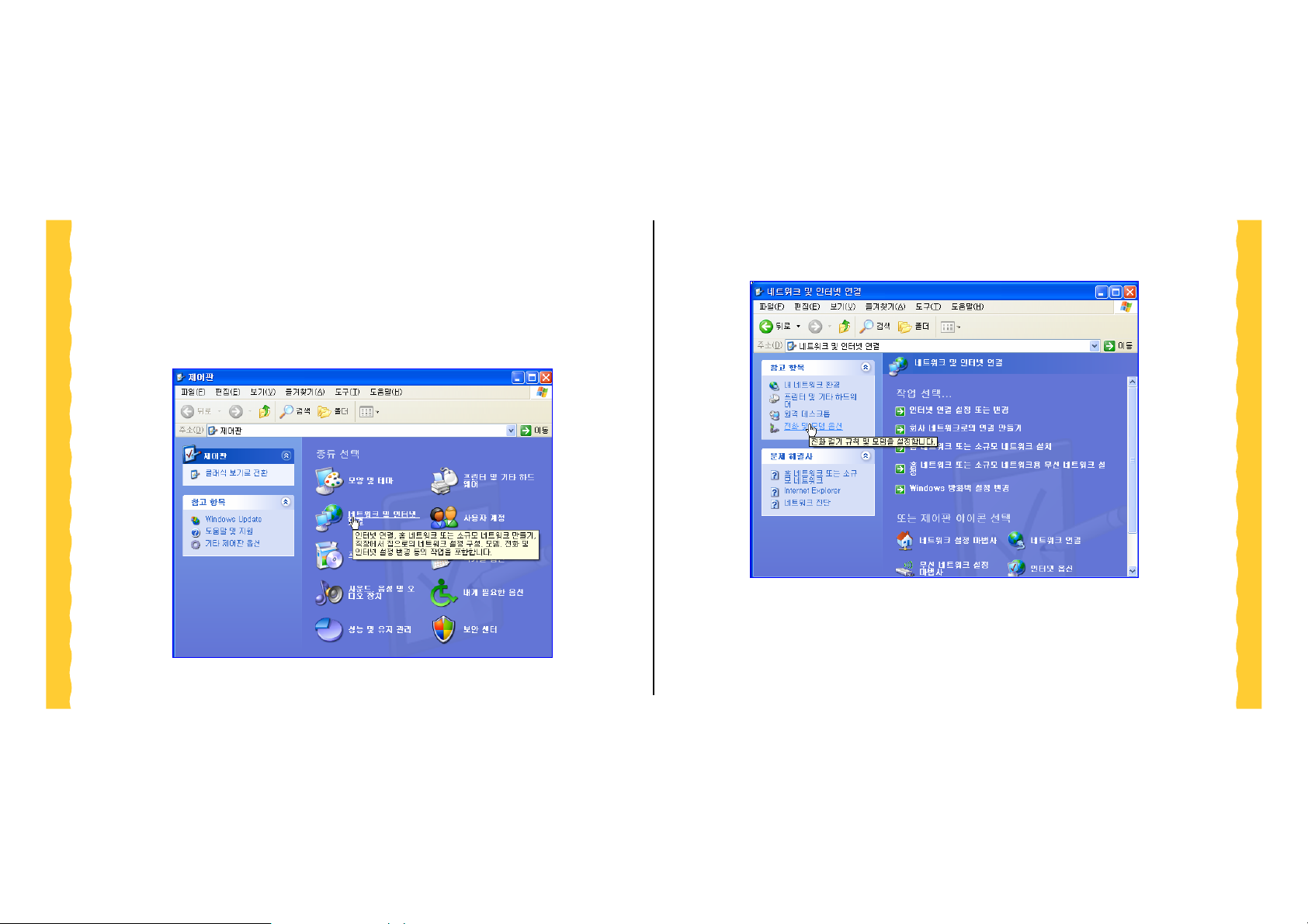
5 Data Communication
z 전화 및 모뎀 옵션 클릭
5.1
표준 모뎀 만들기
z 시작 -> 설정 -> 제어판-> 네트워크 및 인터넷 연결 클릭
-19-
User’s Manual (preliminary)
Page 20
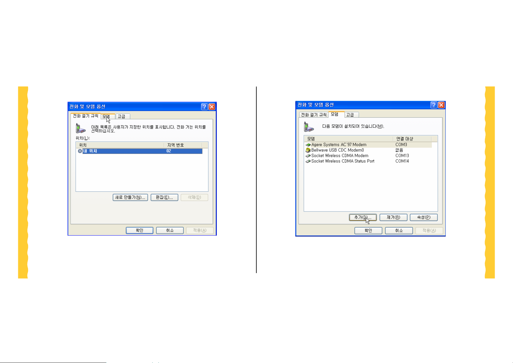
z 모뎀 항목을 클릭.
z 추가 버튼을 클릭
-20-
User’s Manual (preliminary)
Page 21
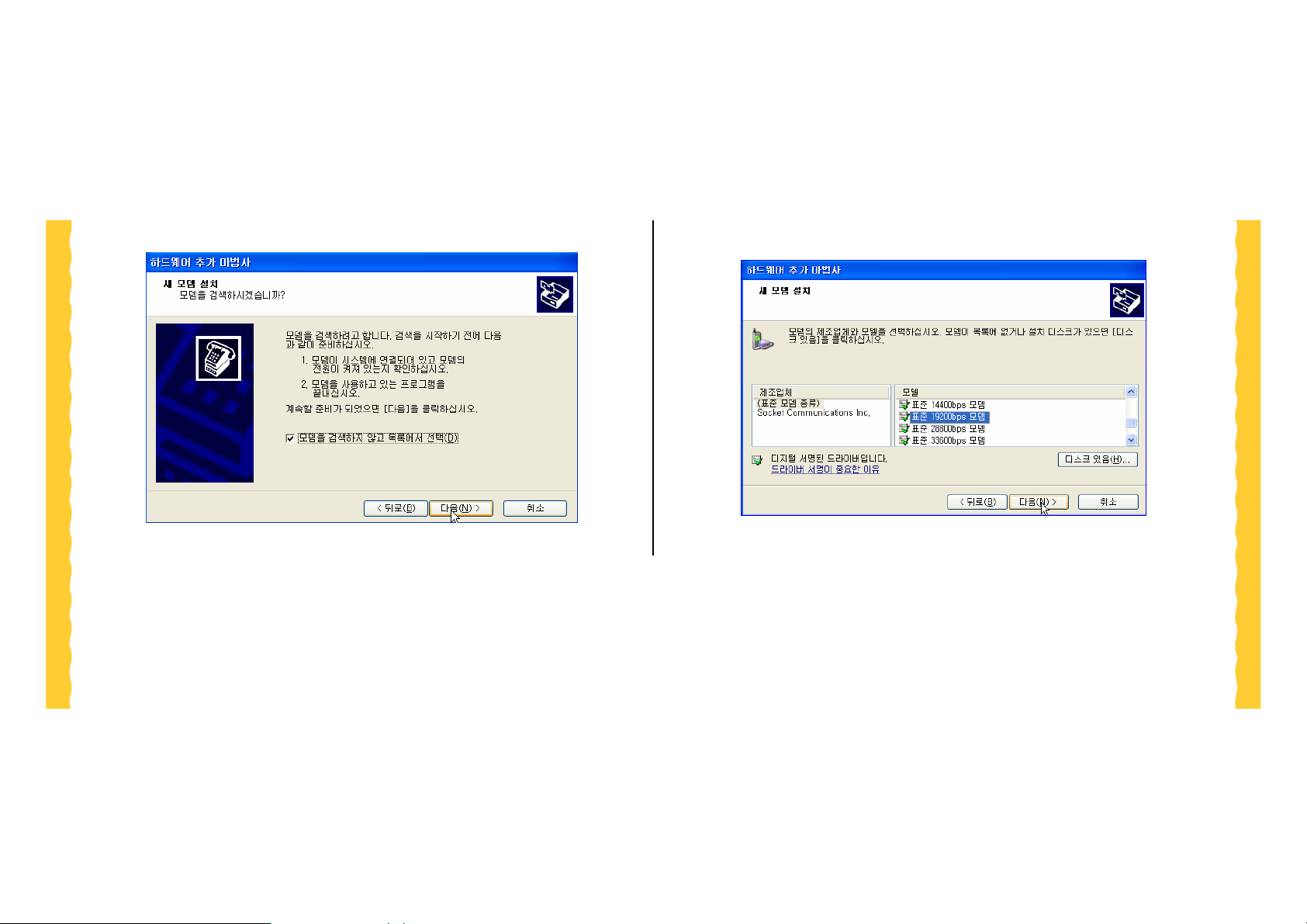
z 다음 버튼을 클릭
z 모뎀 종류와 모델을 선택한 후 다음 버튼을 클릭
-21-
User’s Manual (preliminary)
Page 22
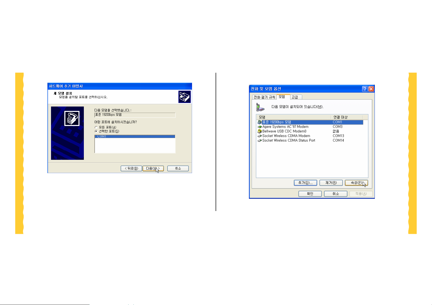
z 모뎀을 설치할 포트를 선택한 후 다음 버튼을 클릭.
z 추가된 모뎀의 속성 버튼을 클릭
-22-
User’s Manual (preliminary)
Page 23
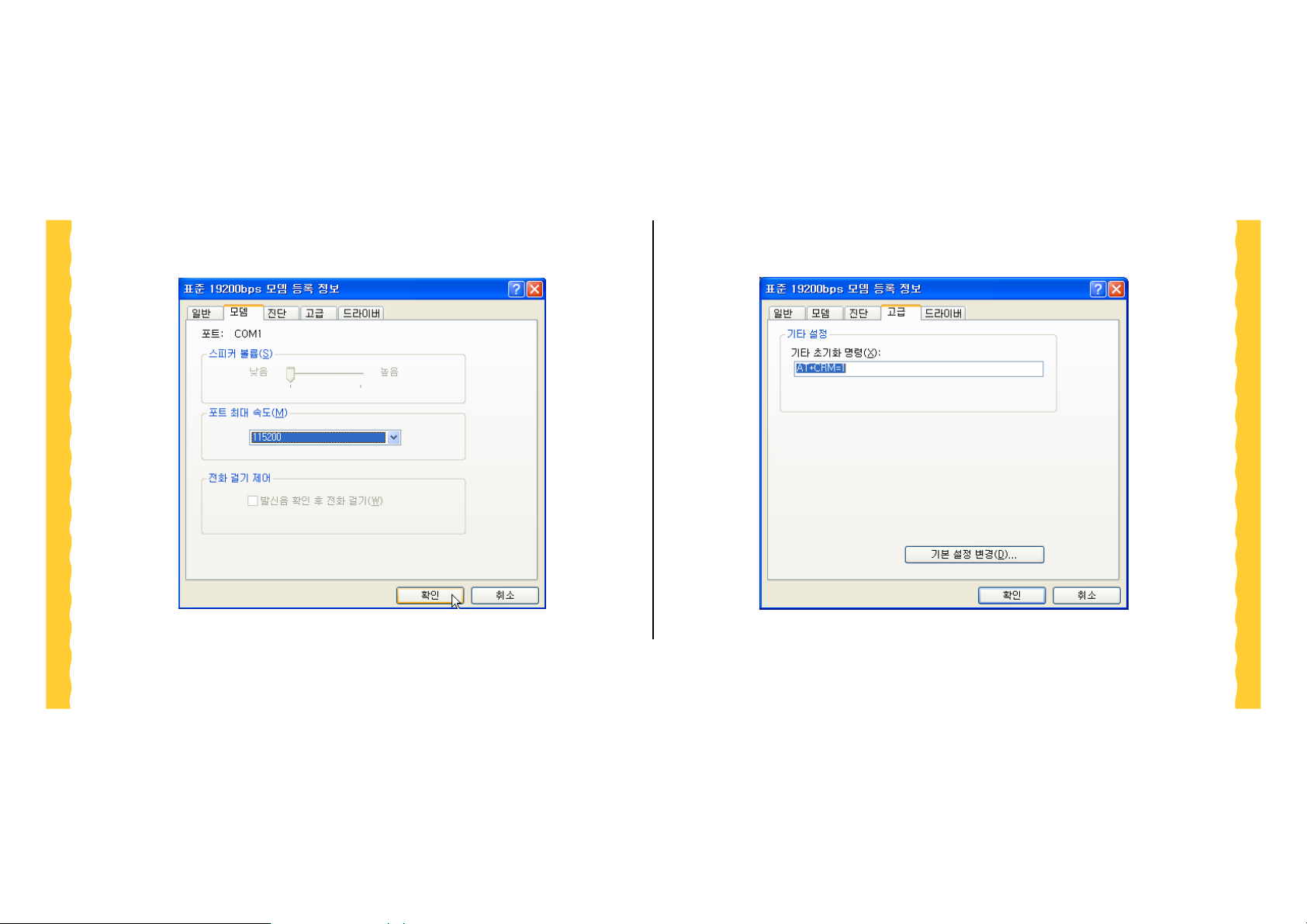
z 모뎀항목에서 포트 최대 속도를 115200 bps로 설정한 후 확인 버튼
을 클릭
z 고급항목에서 초기화 명령에 AT+CRM=1 설정한 후 확인 버튼을 클
릭
-23-
User’s Manual (preliminary)
Page 24
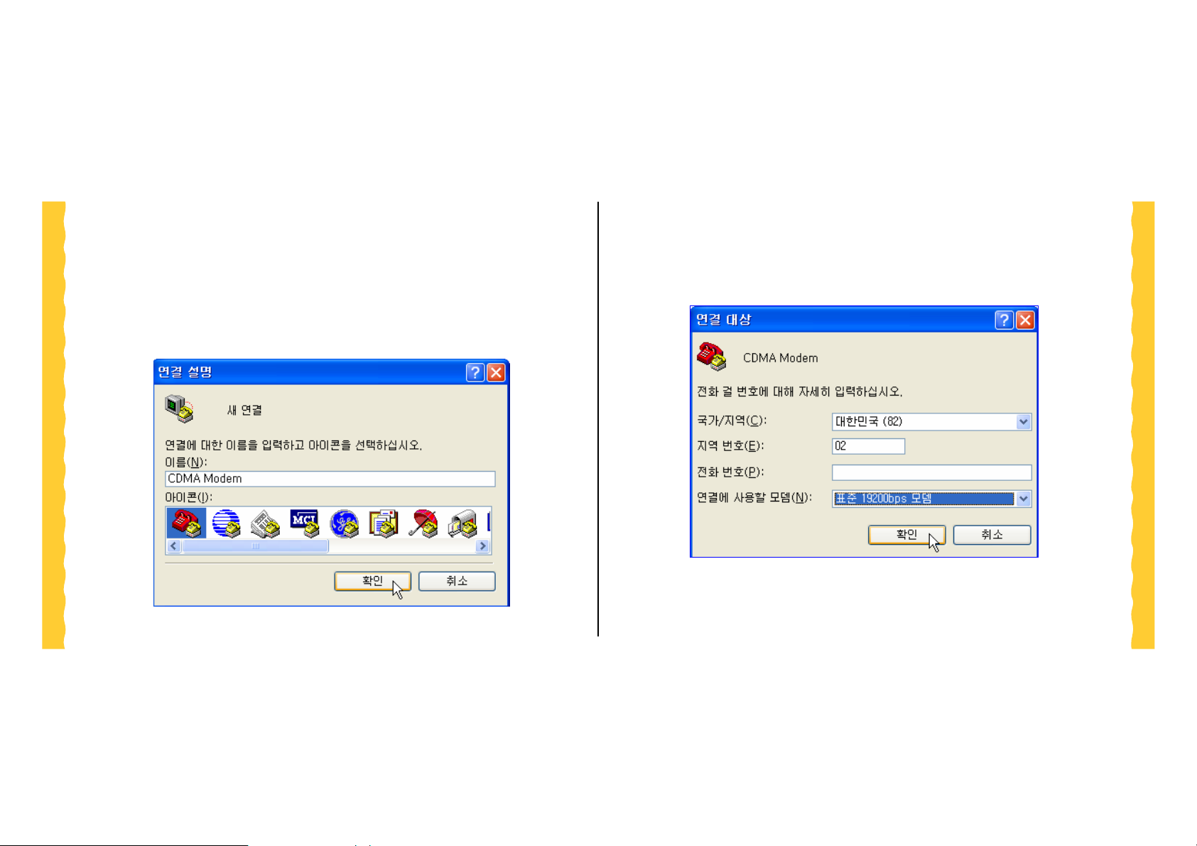
5.2 하이퍼터미널 사용
시작-> 프로그램-> 보조프로그램-> 통신-> 하이퍼터미널 프로그램을 실행
5.2.1 새로 만든 표준 19200 모뎀을 선택한 경우
z 확인버턴 클릭
-24-
User’s Manual (preliminary)
Page 25
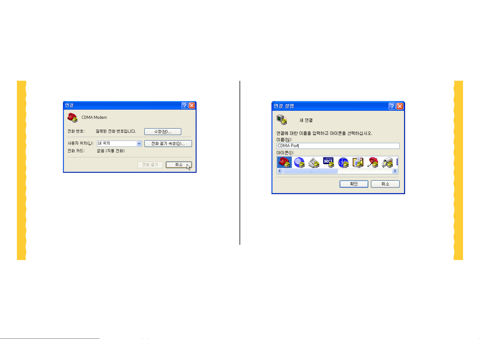
z 아래 화면이 나타나면 취소 버튼을 클릭
5.2.2 직접 포트를 선택한 경우
-25-
User’s Manual (preliminary)
Page 26
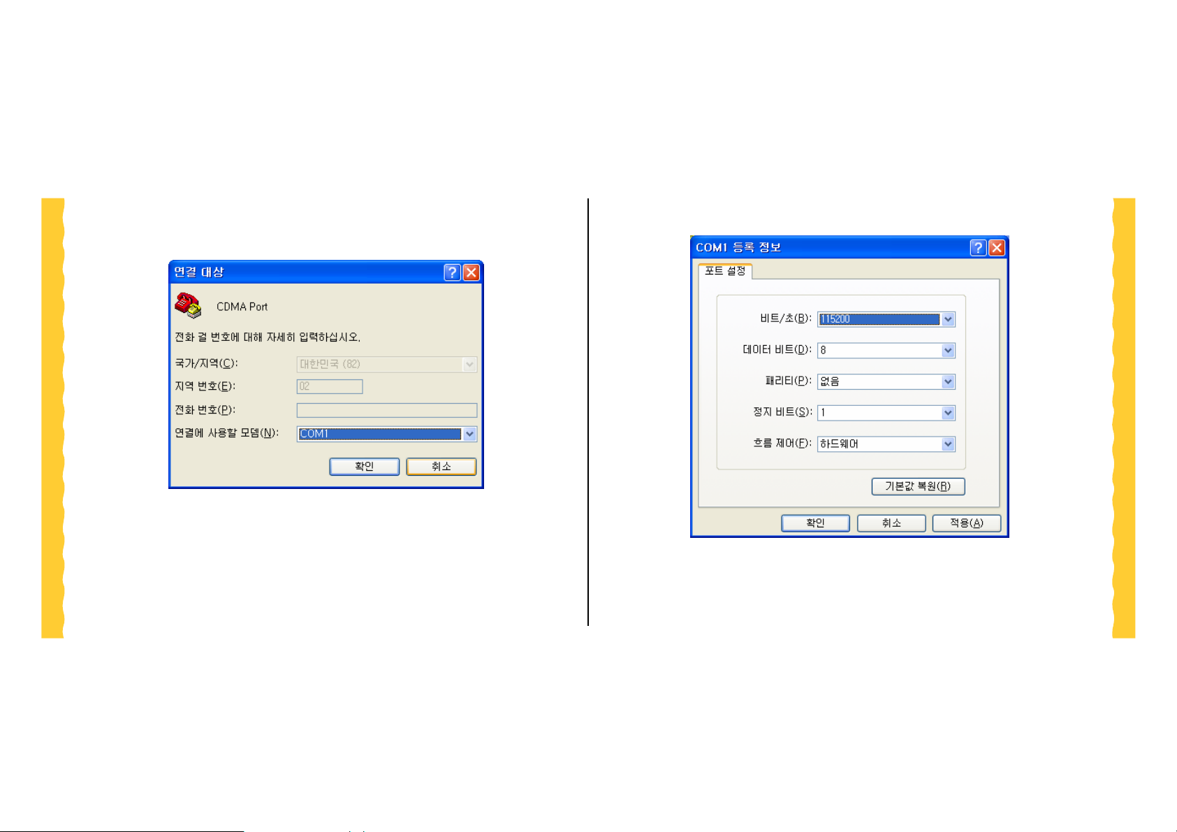
z 모뎀이 연결된 포트를 선택 후 확인 클릭
z 아래의 설정과 같이 선택 후 확인 클릭
하이퍼터미널 창이 뜨면 ‘AT’를 치고 ENTER KEY를 친다. ‘OK’ 가 리턴 되
면 정상 연결된 것이다. 만약 아래와 같이 입력한 ‘AT’가 나타나지 않고
-26-
User’s Manual (preliminary)
Page 27
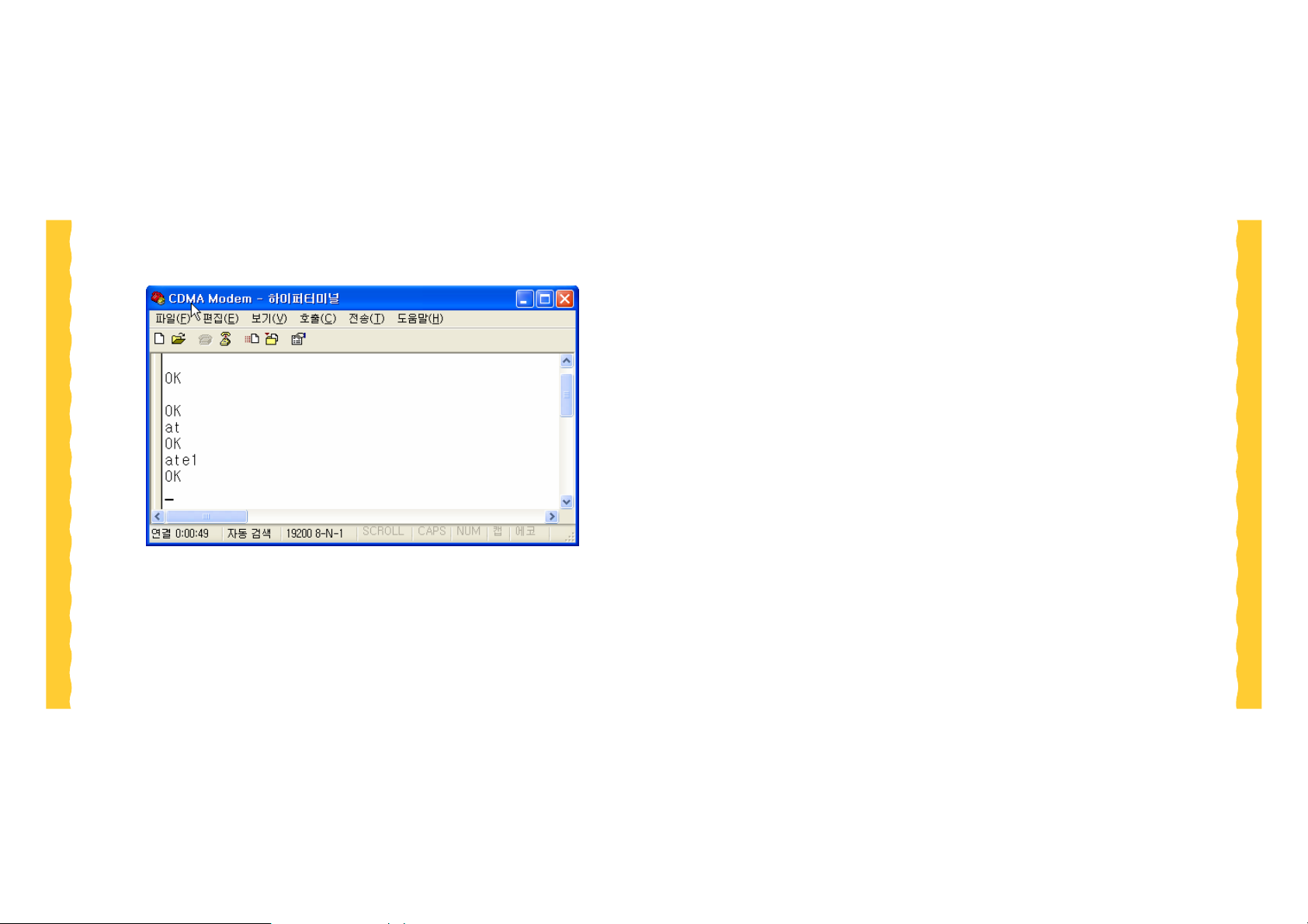
‘OK’만 나타난다면 ‘ATE1’ 명령을 실행하여 사용자가 입력한 값이 모두 나
타나도록 한다.
-27-
User’s Manual (preliminary)
Page 28

5.3 MtoM 접속
MtoM 서비스는 Local 모뎀과 Remote 모뎀간의 1:1 접속을 수행한다. 이 접
속을 위해서는 CRM값이 AT+CRM=129 or 127 값으로 설정되어야 한다.
데이터 접속 발신인 경우
Æ
TE2
TE2
TE2
TE2
Å
Æ
Å
MT2
AT+CRM=129/127
MT2
<RESULT>
MT2
A TD<remote dir_num>
MT2
CONNECT
$009: <n>,<n>
CRM 값 설정
129: SK Telecom
127: LG Telecom
OK 또는 ERROR.
MtoM 호 접속
<remote_dir_num>: 접속하고
자 하는 Remote 전화 번호
CONNECT: 시스템과의 연
결 완료
$009: 시스템과 접속 완료
데이터 접속 수신인 경우
Å
TE2
MT2
CONNECT
$009:<n>,<n>
$002:xxxxxxx
$025:xxxxxxx
CONNECT: 시스템과의 연
결 완료
$009: 시스템과 접속 완료
(Bellwave T ype Notification .)
$002, $025: 부가 서비스 가
입 여부에 따라 통보 여부
가 달라질 수 있다.
(Bellwave Ty pe Notification.)
-28-
User’s Manual (preliminary)
Page 29

5.4 내장 TCP/IP 사용하기
다음의 예는 망사업자를 SKT, 접속할 IP는 123.45.6.789, port는 84, 전송하는
데이터는 “ABC”(0x41 0x42 0x43), 받는 데이터는 “123”(0x31 0x32 0x33)로 가
정한다. (사용자 ID와 Password는 변경될 수 있다. 자세한 설정은 해당 사업
자의 홈페이지를 참고 할 것)
AT command flow
Æ
TE2
TE2
TE2
TE2
TE2
TE2
Å
Æ
Å
Æ
Å
MT2
MT2
MT2
MT2
MT2
MT2
AT$TCPUID=sktelecom
OK
A T$TCPPASSWDNULL
OK
AT+CRM=251
OK
설명
사용자 ID설정명령
사용자 Password설정명
령
소켓 접속을 위한
CRM 설정
TE2
TE2
TE2
TE2
TE2
TE2
Å
Æ
Å
Å
Æ
Å
MT2
CONNECT
MT2
A T$TCPOPEN=123.45.6.789,84
MT2
OK
MT2
$TCPOPEN
MT2
AT$TCPWRITE=414243
MT2
$TCPSENDDONE
PPP연결
016: KTF 연결번호,
019: LGT 연결번호
접속 완료
TCP 소켓을 서버와 연
결하는 명령
TCP 연결 완료 통보
TCP연결을 통한 DATA
전달 명령
전송데이터의 형식은
2-digit hexa-decimal임
(hexa 414243은 ASCII
의 ‘ABC’임)
데이터 전송 성공 통
보
Æ
TE2
MT2
ATD1501
데이터 호 접속명령,
-29-
User’s Manual (preliminary)
TE2
Å
MT2
$TCPREADDATA=313233
데이터 수신 통보
Page 30

ESN 불법 복제 금지
BSM-856 외장형 모뎀에는 각각의 제품을 인식하는 고유번호(ESN: Electrics
Serial Number)가 있습니다.
이 고유번호는 불법으로 변경, 복제하는 행위는 전파법 4조, 전기통신 사업법
57조 및 형법 37조에 의거 3년 이하의 징역이나 1,000만원 이항의 벌금을 받
게 되는 법적 처벌대상이 됩니다. 이러한 불법행위가 확인될 경우 당사가 보증
하는 서비스를 받을 수 없습니다.
Licensed by QUALCOMM Incorporated under one or more of the
TE2
TE2
TE2
TE2
Æ
Å
Æ
Å
MT2
AT$TCPCLOSE
MT2
$TCPCLOSED
MT2
AT$TCPEXIT
MT2
NO CARRIER
받은 데이터의 형식은
2-digit hexa-decimal임
(hexa 313233은 ASCII
의 ‘123’임)
TCP 소켓 CLOSE 명령
TCP 소켓 CLOSE 완료
(통보 메시지)
호 단절 명령, PPP 연
결 해제
호 단절
following Patents.
U.S. Patents No. 4,901,307 5,056,109
5,099,204
5,101,501 5,103,459
5,107,225
-30-
User’s Manual (preliminary)
Page 31

User’s Manual
BSM-856
발행일 2005년 09월
발행처 ㈜벨웨이브
제품 및 서비스 문의
홈페이지
: http://www.bellwave.com
: 02-3460-9741
-31-
User’s Manual (preliminary)
 Loading...