


RFM300-T
Table of contents
 Loading...
USER GUIDE
19-461’02 REV D
RFM300-T Series
Refractometer

RFM300-T User Guide (EN)
Bellingham + Stanley Bellingham + Stanley
Code 19-461
Issue 02
Revision D
Date September 2017
Bellingham + Stanley, a Xylem brand, has been manufacturing high quality optical
instruments in the UK for over 100 years and is a leading manufacturer of
refractometers and polarimeters.
Our current range of products includes optical and digital hand refractometers as well
as a full range of laboratory refractometers and polarimeters available through a
network of trained distributors throughout the world. Process refractometers are also
available through specialist outlets.
Visit our website, www.bellinghamandstanley.com
Stanley, our products and foreign language brochures.
Contact our Sales team to discuss a particular application or to receive details of your
local distributor.
Xylem Inc. recognise all trademarks
2016 Xylem Inc.
Every effort has been made to ensure the accuracy of the contents of the manual.
However, Bellingham + Stanley Ltd. and Xylem Inc. can assume no responsibility for
errors contained in the manual or their consequences.
Printed in UK
, for full details of Bellingham +
Longfield Road 90 Horizon Drive
Tunbridge Wells, Kent TN2 3EY Suwanee, GA 90024
United Kingdom United States of America
Main: +44 (0) 1892 500400 Main: (678) 804 5730
Fax: +44 (0) 1892 543115 Fax: (678) 804 5729
sales.bs.uk@xyleminc.com sales.bs.us@xyleminc.com

Contents
Section 1: Installation ............................................................................. 3
Instrument overview ..................................................................... 4
Menu flow chart ............................................................................ 5
Unpacking .................................................................................... 7
Positioning the system ................................................................. 8
Mains connection ......................................................................... 8
Section 2: Instrument operation ............................................................ 9
Basic operation ........................................................................... 11
Setup Wizard .............................................................................. 13
Measurement Display ................................................................. 14
Measurement settings ................................................................ 20
Calibration and Reading ............................................................. 27
Saving results ............................................................................. 30
Data Menu .................................................................................. 35
Section 3: Instrument Setup ................................................................ 38
Methods ...................................................................................... 39
User accessibility ........................................................................ 42
Reading setup ............................................................................ 51
Communications ......................................................................... 58
System settings .......................................................................... 60
Section 4: System maintenance .......................................................... 63
Maintenance Menu ..................................................................... 64
Information and Help .................................................................. 67
Setting default values ................................................................. 67
Section 5: Specification ........................................................................ 70
Specification ............................................................................... 71
Section 6: Accessories and Contact ................................................... 73
Accessories ................................................................................ 74
Contact ....................................................................................... 77
RFM300-T 19-461’02 Rev. D September 2017 Page 1

This symbol is an internationally agreed indicator that the
and facilities are in place.
Declaration of conformity
According to ISO/IEC 17050-1 & 2: 2004
Manufacturer's Name Bellingham + Stanley
Manufacturer's Address Longfield Road,
Tunbridge Wells,
Kent TN2 3EY
United Kingdom
declares that the product
Product Name RFM300-T Series Refractometer
Model Number All
Is designed to conform to the following Product Specifications:
Safety:
BS EN 60950-1:2002
Applied and met EMC test standards:
Emissions
EN 61326-1:2013
• Radiated emissions CISPR 11:2009 inc.
A1:2010, Class A
• Conducted emissions, ac port CISPR 11:2009 inc.
A1:2010, Class A
• Conducted emissions, ethernet port CISPR 11:2009 inc.
A1:2010, Class A
EN 61000-3-2:2014
• Mains harmonics Class A
EN 61000-3-3:2013
• Mains voltage flicker (dmax=4%)
Immunity:
EN 61326-1:2013 - Basic immunity requirement (Table 1)
• Electrostatic discharge EN 61000-4-2:2009
• Radiated RF interference EN 61000-4-3:2006 inc.
A1:2008 & A2:2010
• Fast transient bursts EN 61000-4-4:2012
• Surge EN 61000-4-5:2014
• Conducted immunity EN 61000-4-6:2014
• Voltage dips and interruptions EN 61000-4-11:2004
Supplementary:
The product herewith is designed to comply with the requirements of the EMC
Directive 2014/30/EU and the Low Voltage Directive 2014/35/EU.
The symbols below are used throughout this user guide.
Caution or warning.
Hint or tip.
Page 2 19-461’02 Rev. D September 2017 RFM300-T
product bearing it should not be disposed of as general
waste or garbage which might end up in landfill sites, but
should instead be sent for special processing and/or
recycling in those countries where appropriate legislation
Electrical hazard.

Section 1: Installation
Instrument overview ............................................................................... 4
Menu flow chart ....................................................................................... 5
Unpacking ................................................................................................ 7
Contents list .................................................................................. 7
Positioning the system ........................................................................... 8
Mains connection .................................................................................... 8
Power requirements ..................................................................... 8
Warning ........................................................................................ 8
RFM300-T 19-461’02 Rev. D September 2017 Page 3

Instrument overview
The RFM300-T Series Refractometer is a self-contained easy to use
instrument suitable for measuring the refractive index of samples in
demanding factory environments as well as for use as a primary quality
control tool.
The instrument is housed in a case which is light in weight whilst being
extremely rugged. The ergonomic design ensures spills are dealt with by
the sloping of the case and the PEEK spill barrier and stainless steel
prism dish gasket ensure high resistance to chemical attack from the
majority of commonly used samples. The large sampling area on the
prism surface allows measurements of not only homogenous fluids like
juices, sodas and edible oils but also difficult to read samples like fruit
pulps and industrial resins.
Sample temperature is controlled by the Peltier Temperature control
system and intelligent temperature management which enables rapid
stabilisation and little noise. The low profile sample dish and non-contact
presser makes sample application and cleaning easy.
A high definition, capacitive touchscreen display facilitates operation in
factory environments, even when operated whilst wearing gloves, and the
GUI helps the operator quickly manoeuvre through the user and
configuration menus. On-screen graphical prompts support simple
operation such as method loading, calibration and routine maintenance.
The instruments conform to a number of industry measurement
standards and offer operational features that allow use in an environment
controlled by FDA regulation 21 CFR Part 11. Built in RFID technology
helps provide clearance and a log of operator and configuration functions.
Readings can be printed via USB, serial or network ports. Alternatively
they can be stored in a database or as secure PDFs to later download via
either a USB removable storage device or across a local area network.
A wide range of accessories including printers, barcode readers and USB
keyboards is available.
Page 4 19-461’02 Rev. D September 2017 RFM300-T
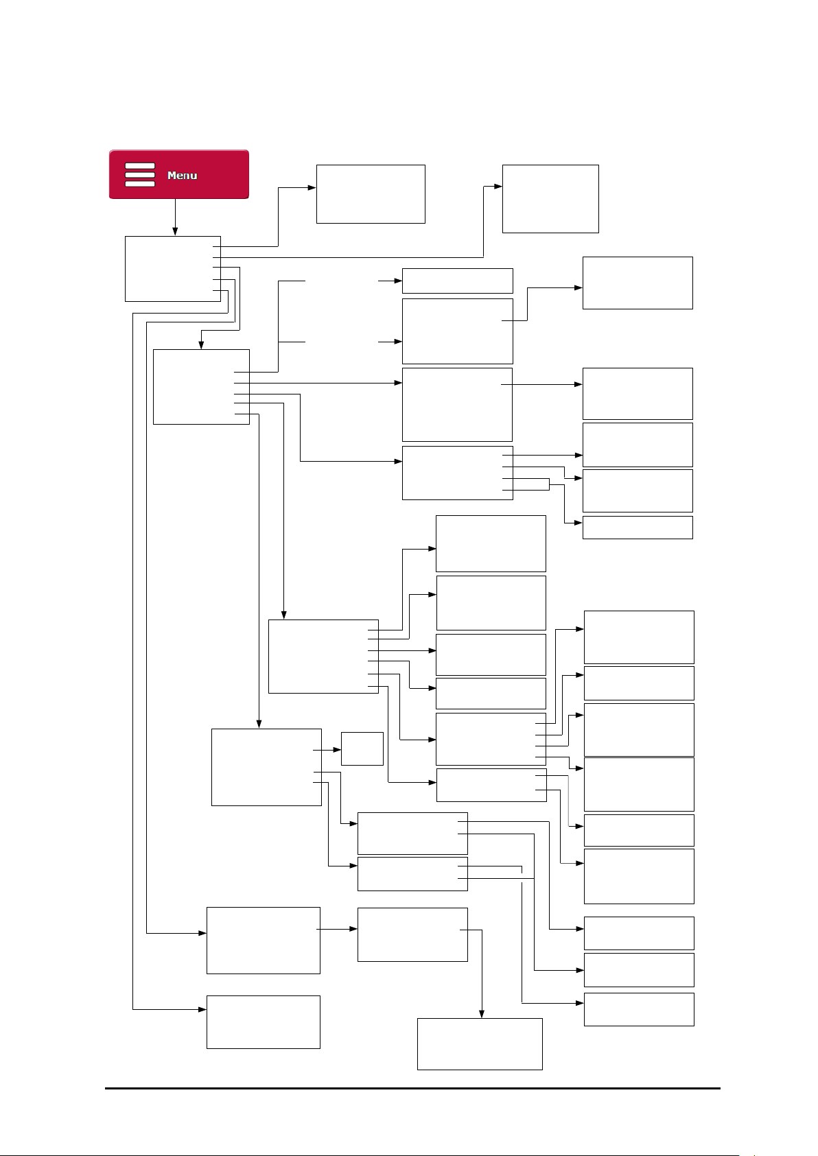
Menu flow chart
1. Calibration
2. Data
3. Setup
4. Maintenance
5. Help
1. Setup Wizard…
2. Methods
3. Users
4. Reading
5. Recording
6. System
1. Zero
2. Span (Top Calibration)
3. Undo
4. Report
If Methods are
not enabled
If Methods are
enabled
1. Use Methods
N. Add new…
S. Settings…
1. normal
2. zero
3. span
N. Add new…
P. Protection
1. administrator – 000
2. calibrator – 355
3. operator – 123
(default PINS shown)
1. Recurrence
2. Appl. Correction
3. Scales
4. Temp. Comps
1. none 5. statistics
2. single 6. multi
3. save
4. single + save
1. Saved Results
2. System Log
3. Copy PDFs to USB
4. Move PDFs to USB
5. Export logs to CSV
1. Use Methods
2. Hide Preset
3. Selection Type
4. Print List…
1. low
2. medium
3. high
4. custom
1. single
2. continuous
3. auto single
1. none
2. offset
3. citric acid
N. Add new…
1. Mode
2. Printer
3. CSV (Lims)
4. Record After Read
5. Traceability
6. Ports
1. Language
2. Remote Display
3. Display Brightness
4. Time / Date
5. Temp. Control
6. Clone From Backup
1. Maintenance Report
2. Filter Change Reminder
3. Backup to USB
4. Clean Screen
5. Update Software
1. off
2. on
1. Date Format
2. Summer Time
3. Set Clock
1. Mode
2. Disable Presser
1. New Filters Fitted
2. Frequency
3. Last Changed
4. Replacement Status
1. none 5. network
2. serial
3. usb
4. pdf
1. none 4. usb
2. serial
3. network
1. no
2. yes
1. Batch Codes
2. Auto Increment
3. Log Users
4. Remember Text
1. Serial Port
2. Network
1. off
2. number
3. text
4. dateinc
1. off
2. on
1. off
2. number
3. text
4. login
1. off
2. batch
3. user
4. batch and user
1. Baud Rate
2. Word Length
1. DHCP
2. IP Address
3. Subnet Mask
4. Default Gateway
1. dd/mm/yy
2. mm/dd/yy
1. no
2. yes
1. Information
2. Contact
3. User Guide
4. PC Software
1. off 5. 2 months
2. 1 week 6. 3 months
3. 2 weeks 7. 6 months
4. 1 month
1. off
2. on
RFM300-T 19-461’02 Rev. D September 2017 Page 5

Page 6 19-461’02 Rev. D September 2017 RFM300-T
Refractometer module
only
Unpacking
Carefully remove all of the packing material. It is recommended that the
box and other packing materials are retained so that, should the need
arise, the refractometer can be safely returned to the supplier for service.
Check that all parts listed below are present and that no transit damage
has occurred. If any are damaged or missing, contact the supplier
immediately.
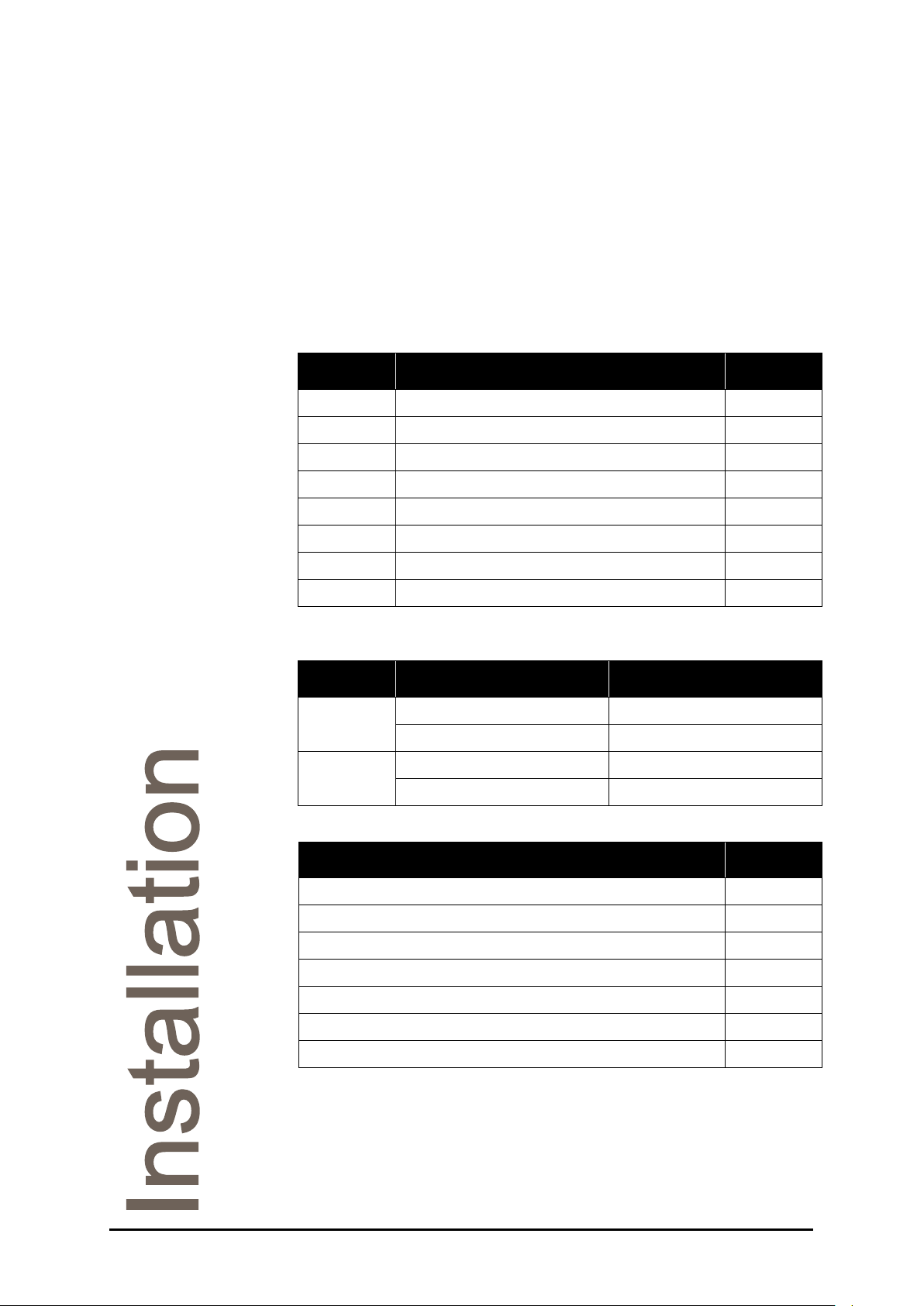
Contents list
Quantity Item Code
1 RFM300-T Series Refractometer See below
1 Mains lead See below
1 Power supply 55-105
1 Quick Start Guides 19-406
2 Card type ID tag 37-530
2 Spare air vent filter 22-482
2 Touchscreen stylus 19-203
1 Touchscreen protector 19-204
RFM300-T refractometer code numbers:
Model Complete refractometer
RFM330-T
RFM340-T
Mains lead code numbers:
Moulded plug type for Code
Switzerland 61-181
Denmark 61-182
India / South Africa 61-188
Australia 61-189
19-30 19-330
19-31 19-331
19-40 19-340
19-41 19-341
RFM300-T 19-461’02 Rev. D September 2017 Page 7
UK 13 Amp square pin to BS1363/A 61-191
United States (3 pin) 61-192
Europe (Schuko) 61-193
Positioning the system
Place the instrument on a flat and stable bench that is:
• Dry and indoors.
• Capable of holding the instrument’s weight.
• Away from draughty or hot equipment like fans or heaters.
• Out of direct sunlight or strong ambient light.
• Away from potential sources of interference, such as RFI
generating equipment.
• Within reach of a power point.
• Not using a power circuit that also has large motors or noise
generating equipment connected to it.
Do not block the air vents.
Mains connection
The power supply adapter is supplied with a moulded mains cord and
plug to suit one of several socket types. For UK leads, replace the fuse
only with the type indicated on the plug.
Power requirements
Voltage 110 to 230 V ~ ±10%
Frequency 50 to 60 Hz
Maximum current 2 A
Warning
RISK OF ELECTRIC SHOCK:
• For indoor use only.
• Must be kept dry.
• Disconnect the equipment from the mains supply before
unplugging the mains lead from the instrument.
WARNING:
• Do not cover, designed to operate with free air convection.
• No cleaning required
A waterproof power supply adaptor, code no. 55-250, which can be used
in damp environments, is available as an optional extra.
Page 8 19-461’02 Rev. D September 2017 RFM300-T

Section 2: Instrument
operation
Basic operation ..................................................................................... 11
Switching on and off ................................................................... 11
Manoeuvring through menus ..................................................... 11
Setup Wizard .......................................................................................... 13
Measurement Display ........................................................................... 14
Title Bar ...................................................................................... 15
Reading display and data ........................................................... 17
Reading configuration ................................................................ 18
Action Buttons ............................................................................ 18
Menu Buttons ............................................................................. 19
Measurement settings .......................................................................... 20
Changing settings ....................................................................... 20
Using the Reading Configuration Panel ..................................... 21
Basic settings ............................................................................. 21
Scale........................................................................................... 21
Temp. Comp. (temperature compensation) ............................... 21
Set Temp (temperature control set-point) .................................. 22
Advanced settings ...................................................................... 22
Stability ....................................................................................... 22
Limits .......................................................................................... 24
Resolution .................................................................................. 25
Secondary reading ..................................................................... 25
Using Methods ........................................................................... 26
Calibration and Reading ....................................................................... 27
Zeroing the instrument ............................................................... 27
Auto Zero .................................................................................... 28
Taking a reading ......................................................................... 28
Span calibration .......................................................................... 29
Undo calibration ......................................................................... 29
Calibration report ........................................................................ 29
Saving results ........................................................................................ 30
Set the print mode ...................................................................... 30
Print formats ............................................................................... 31
Traceability ................................................................................. 31
Batch codes ................................................................................ 32
User codes ................................................................................. 32
RFM300-T 19-461’02 Rev. D September 2017 Page 9

Remember text ........................................................................... 32
Statistics print mode ................................................................... 33
Data Menu .............................................................................................. 35
The Reading Log ........................................................................ 35
The System Log ......................................................................... 36
Downloading Logs ...................................................................... 36
Downloading PDFs ..................................................................... 36
PDF and FTP ............................................................................. 37
Page 10 19-461’02 Rev. D September 2017 RFM300-T
Basic operation
Switching on and off
Plug in the power supply and switch on the mains supply, after startup
the instrument will show a loading screen indicating the software version.
Once loaded, the instrument will be in standby mode. To switch on, swipe
a finger or stylus across the display. After a few moments the instrument
will show the Measurement Display (or the Setup Wizard if switching on
for the first time). An Auto Zero will be requested once the instrument
temperature has stabilised, see Page 27
To switch to standby mode press and hold the Menu Button for several
seconds and select Yes on the confirmation screen. It is then safe to turn
off the mains supply and disconnect the power lead.
Manoeuvring through menus
The RFM300-T Series Refractometer features a capacitive, highresolution touchscreen display. On-screen buttons can be easily used by
simply touching the display. A compatible stylus can also be used, as
supplied with the instrument.
Use the supplied stylus and screen protector to keep the touchscreen
clean and avoid damage from improper use. The touchscreen should
only be used with a finger or stylus designed for use with a capacitive
touchscreen.
Alternatively, a USB keyboard, available from Bellingham + Stanley, can
be used to select items and navigate menus. The USB keyboard can
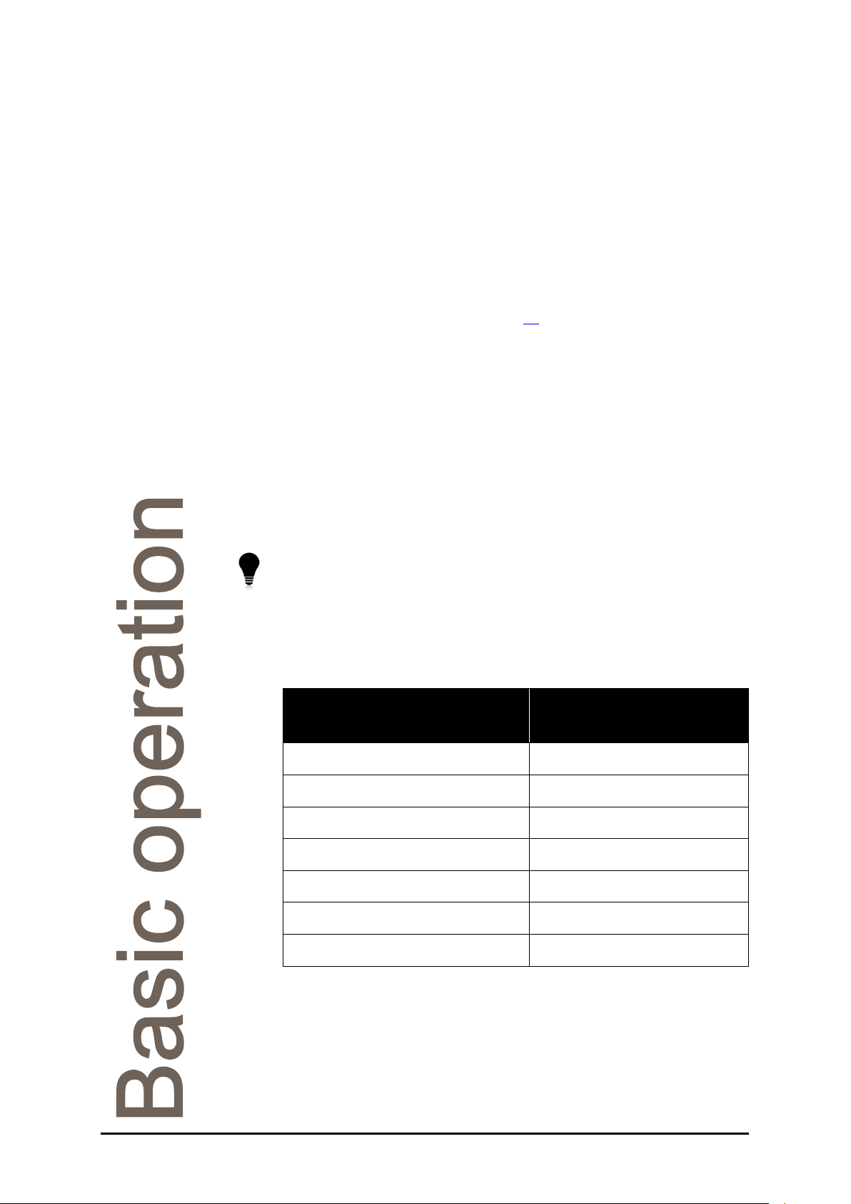
perform the following actions from the Measurement Display.
.
USB keyboard key Function
F1 / Space Start a reading
F2 / Enter Print / Save the current reading
F3 / z Zero
F4 / m Open Mode / Methods
F5 / Esc Open Main Menu
F6 / d Data
Left / Right Logout
Whilst in a Menu, options that are currently unavailable will appear faded.
RFM300-T 19-461’02 Rev. D September 2017 Page 11
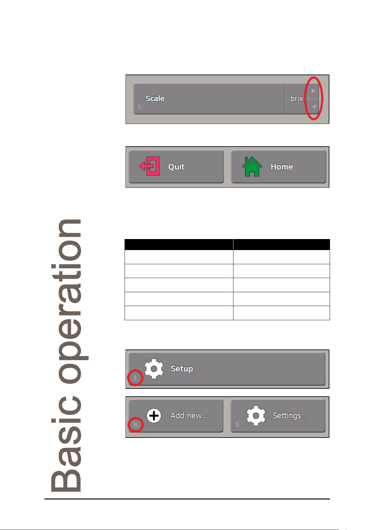
Many buttons feature a quick select option, indicated by the two arrows
on the right of the button. Simply touch either arrow to cycle through the
possible settings.
When in a menu, the Quit and Home buttons become available.
Press the Quit Button to return to the previous menu. Any changes made
will be saved. The Home Button will exit to the Measurement Display,
again any changes made will be saved.
The USB keyboard can be used for Menu navigation.
USB keyboard key Function
Up / Down Change highlighted button
Enter Push highlighted button
Left / Right Cycle quick select options
Esc Quit
Shift + Esc Home
The USB keyboard also allows menu items to be selected by pressing
the related number or letter shown on the left of the on-screen buttons.
Text or number entry boxes can be completed with either the on-screen
keypads or a USB keyboard.
Page 12 19-461’02 Rev. D September 2017 RFM300-T
Setup Wizard
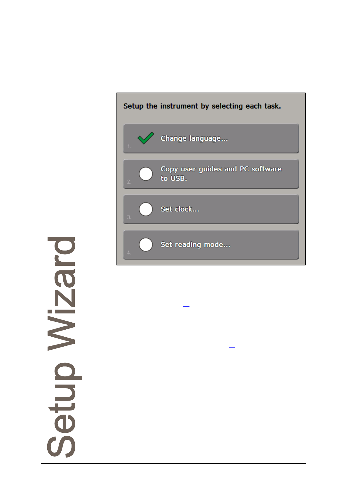
When switching on for the first time, after the instrument has completed
its startup procedures, the Setup Wizard will appear. First select the
desired language. A list of different options will then appear.
• Copy user guides and PC software to USB: Makes copies of
all user guides and PC software compatible with the instrument
to a removable USB storage device.
• Set clock: Set the instrument to local time and set the date
format, see Page 60
• Set reading mode: Make changes to the measurement settings,
see Page 20
• Set record settings: Specify how reading results will be printed
or saved, see Page 30
• Set user settings: Alter the security settings to a level suitable
for the area of operation, see Page 42
Select each in turn and alter the settings as desired, then press Quit to
return to the Setup Wizard Menu. Each menu will be marked by a tick
after the settings are altered.
Once all required settings are changed press Quit on the Setup Wizard
Menu to show the Measurement Display.
.
.
.
.
RFM300-T 19-461’02 Rev. D September 2017 Page 13

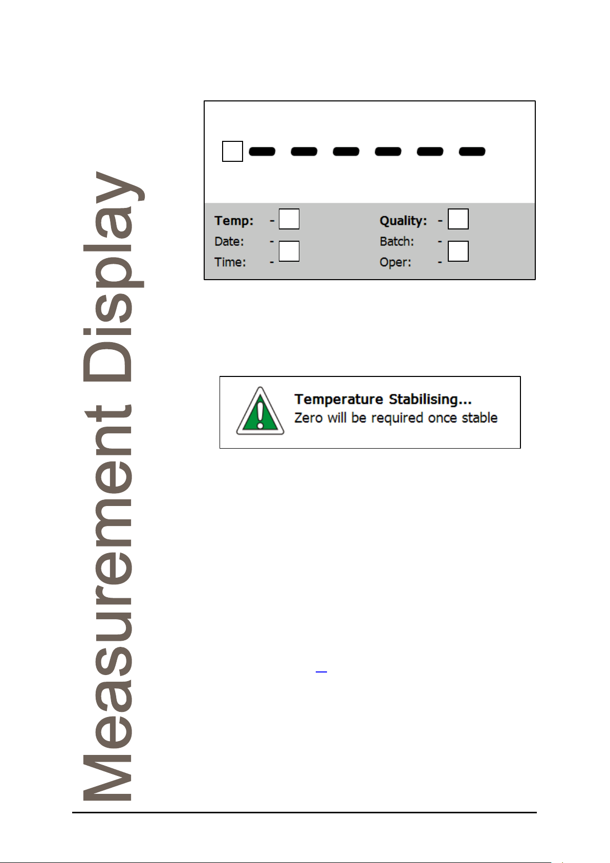
Measurement Display
From the Measurement Display readings can be taken, viewed and
saved. Quick access to all the frequently used features of the instrument
is also available.
Title bar
Reading
display and
data
Reading
configuration
Action
buttons
Menu
buttons
Page 14 19-461’02 Rev. D September 2017 RFM300-T
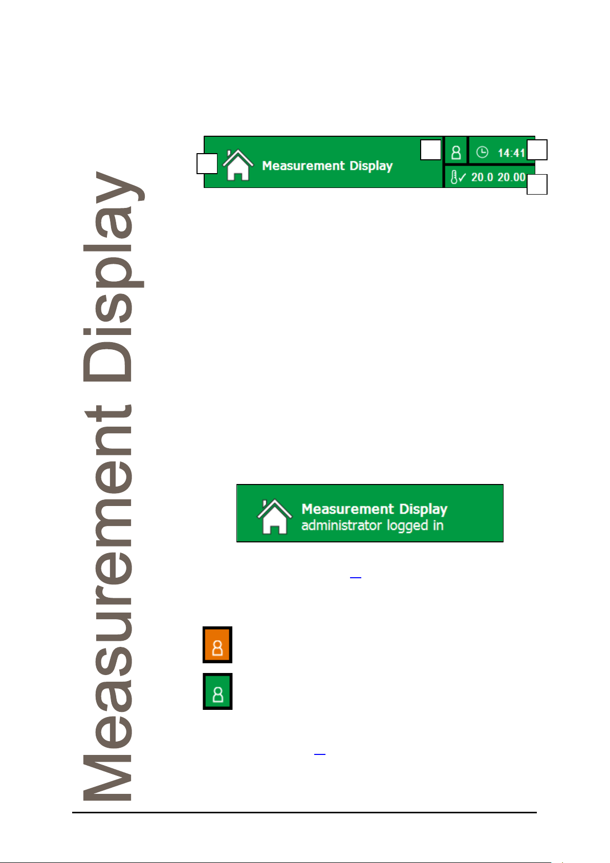
Title Bar
The title bar contains several elements that will be displayed on every
screen.
1
1. Title: Current location within the instrument’s menu structure.
The colour of the title bar will change depending on the current operation.
Red: In the Main Menu structure. This indicates that changes will be
made to the instrument’s settings.
Orange: In Modes/Methods. Changes made will affect the measurement
settings.
Green: Associated with taking and initiating readings.
Blue: Within a process that affects how the current reading will be printed
or saved.
Purple: For calibration requests.
Brown: Whilst exporting or viewing saved readings, logs or PDFs.
These colours are replicated on the associated Action and Menu buttons.
If security settings are in use, the username of a logged-in user will also
appear here whilst in the Measurement Display and in the Main Menu.
3 2
4
Pressing the title bar will also log out the current user. User accessibility
is discussed in detail from Page 42
2. Security status: A further indicator for whether a User is logged in,
displayed in all menus within the instrument.
Users logged out, symbol orange
User logged in, symbol green
3. System clock: Shows the current system time in a 24 hour format. To
alter the time, see Page 60
RFM300-T 19-461’02 Rev. D September 2017 Page 15
.
.
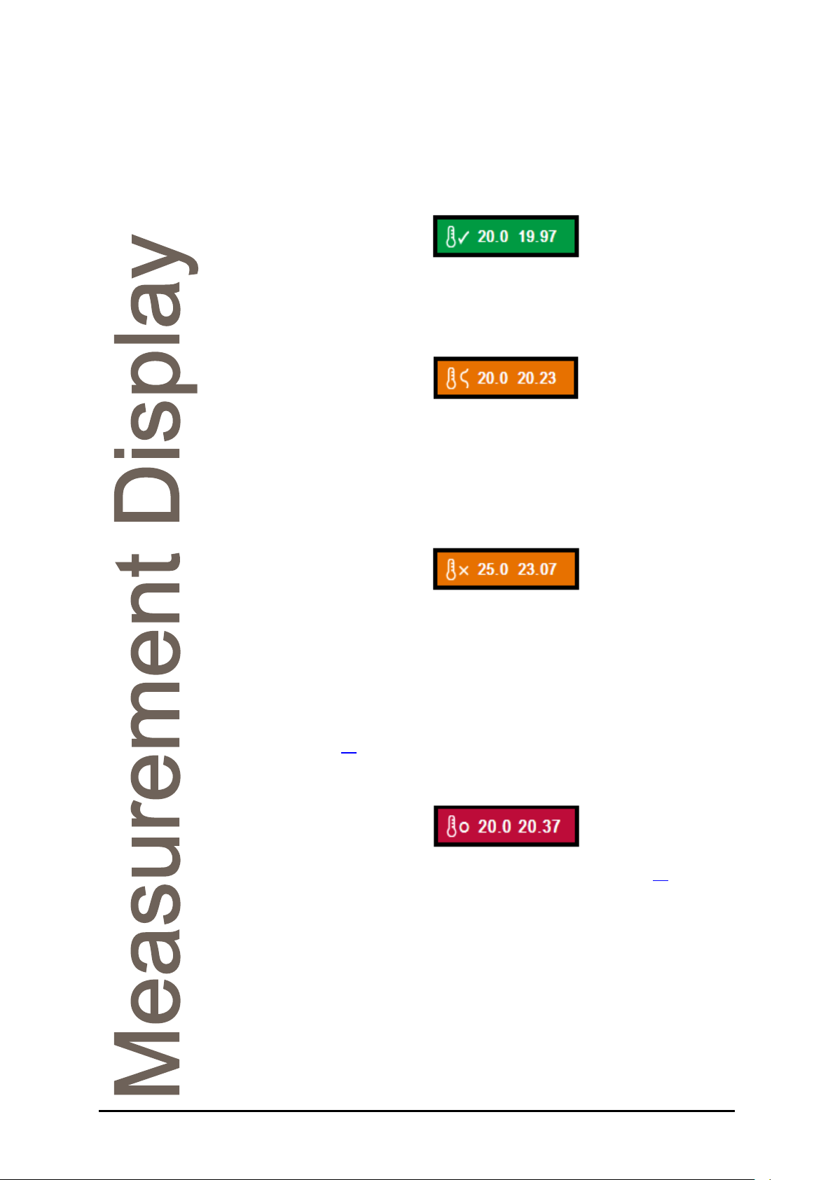
4. Temperature control status: Displays the stability status, prism set
temperature and current prism temperature. The colour and status
symbol will change depending on the set-point temperature and the
measured temperature.
• Temperature stable
The tick indicates that the measured prism temperature (second value) is
stable to within ±0.05°C of the set-point temperature (first value).
• Temperature stabilising
This will often occur when applying a fresh sample which has a
significantly different temperature to the prism.
The stability symbol oscillates to show that the prism temperature is not
yet stable.
• Temperature changing
This will occur when the temperature set-point is changed or after the
instrument is switched on.
The stability symbol becomes a cross and there can be a significant
difference between the measured temperature and the set-point
temperature.
An Auto Zero will be required after changing the temperature set-point,
see Page 28
.
• Temperature control off
If the instrument temperature control is turned off (see Page 61
) the
control status will turn red.
Page 16 19-461’02 Rev. D September 2017 RFM300-T
Reading display and data
1
2 3
4 5
1. Reading result: After taking a reading, the final result will be displayed
here. The result will be displayed in the units set in the Mode/Method,
shown in the reading configuration section of the Measurement Display.
Warning and alert messages will also appear here. For example, after the
temperature set-point is changed, a Zero calibration will be requested.
2. Temperature: The temperature that the prism was at when the
reading was recorded will be displayed here.
3. Quality: The Quality figure is derived from the optical pattern that falls
upon the instrument detection system. A high Quality value indicates that
the optical pattern is well-defined, making the reading signal easy to
resolve. A low Quality value, caused for instance by an opaque sample or
poor sample application, means a less well defined optical pattern so the
reading will be less reliable.
The Quality value for the sample used to set Zero is automatically set to
100, which can then be used as a reference with which to compare other
measured samples.
4. Date/Time: When the displayed result was obtained.
5. Traceability data: Displays batch and operator codes associated with
each reading. See Page 31
for details on traceability settings.
RFM300-T 19-461’02 Rev. D September 2017 Page 17
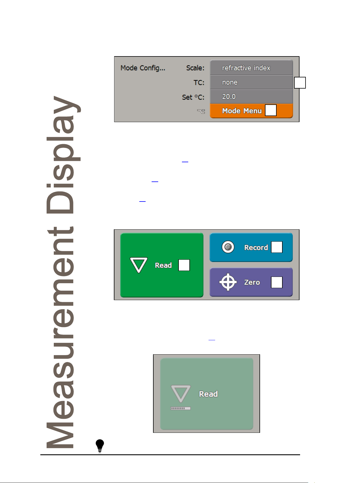
Reading configuration
1
2
1. Reading Configuration Panel: Displays the measurement settings for
the currently displayed reading or, if a result is not currently displayed,
the settings to be used for the next reading. It also allows for quick
changes to the Basic reading settings, see Using the Reading
Configuration Panel, Page 21
2. Mode button: Gives access to edit all Basic and Advanced reading
settings (Page 20
When working with Methods the Reading Configuration Panel is disabled,
see Page 39
).
.
.
Action Buttons
2
1
3
1. Read button: Initiates a reading. Readings will be taken in the manner
described in Mode or the current Method, the Basic settings can be seen
in the Reading Configuration screen section.
If using continuous read mode (Page 51
the Read button.
Holding down the Read button for several seconds will display the
Reading setup menu.
Page 18 19-461’02 Rev. D September 2017 RFM300-T
) a progress bar will appear on
1
2
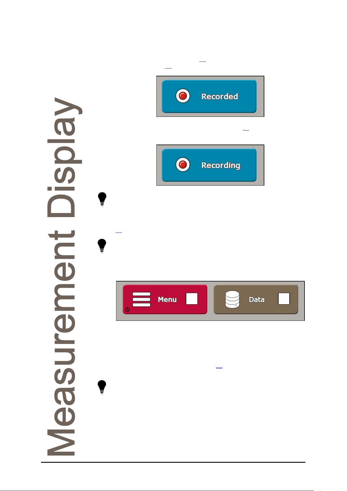
2. Record button: If a result has yet to be printed or saved and a printer
is set, the record icon will appear grey. Pushing the button will record the
result to the Reading Log (Page 35
settings, see Page 30. The record icon will then turn red.
) or printer depending on the print
If the print mode is set to record after read (Page 30
be red permanently.
Holding down the Record button for several seconds will display the
Recording Menu for quick change of printer settings.
3. Zero button: Initiates a Zero calibration routine. A Zero can be
performed with any sample but distilled water is typically used. See Page
for Zero calibration procedure and recommendations.
27
Holding down the Zero button for several seconds will open the
Calibration Menu.
) the record icon will
Menu Buttons
1. Menu button: Opens the instrument’s Main Menu from where all
instrument settings can be changed. Hold for several seconds to switch
the instrument to standby.
2. Data button: Opens the Data Menu, this includes viewers for saved
results and the System Log (see Page 35
download the results and any saved PDFs.
Holding down the Data button for several seconds will open the Saved
Results viewer.
RFM300-T 19-461’02 Rev. D September 2017 Page 19
) as well as the ability to
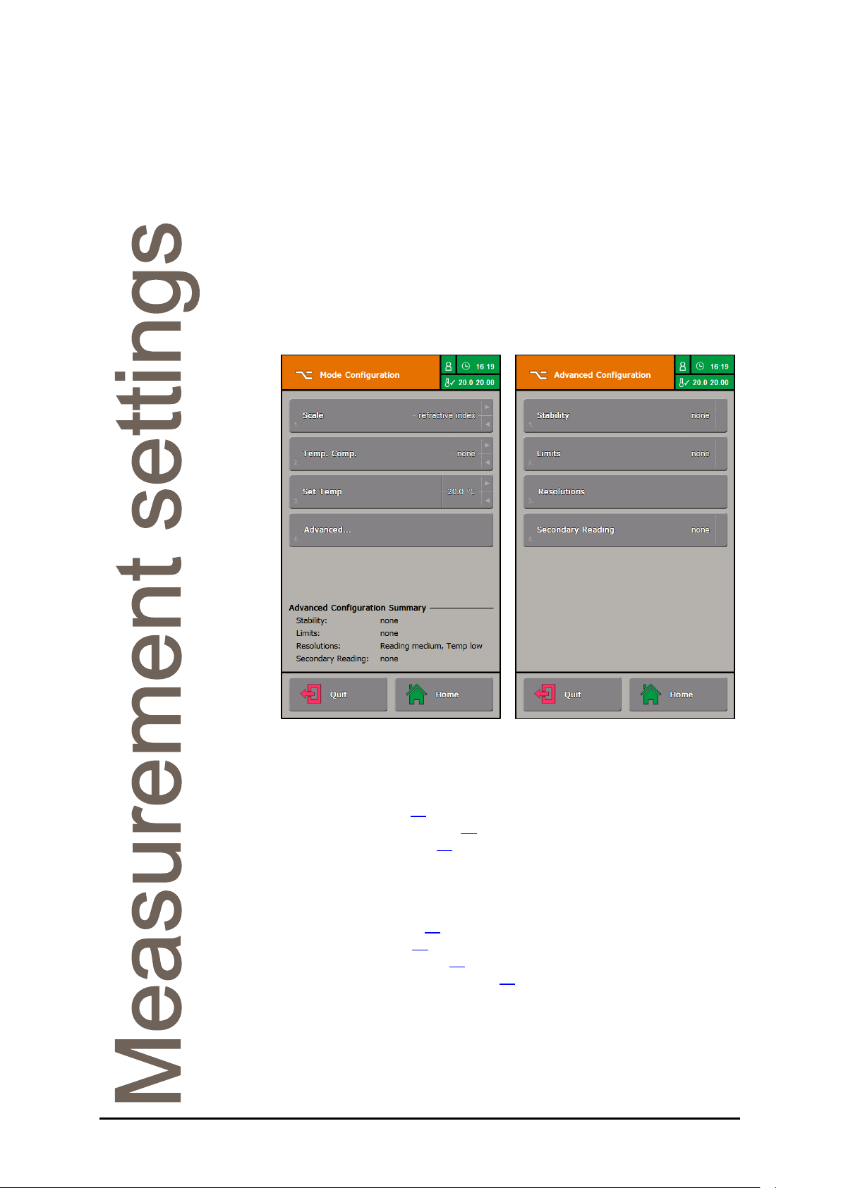
Measurement settings
The measurement settings affect how a reading is collected and
presented. If different sets of measurement settings are required then
Methods can be enabled. For simplicity, the instrument is supplied in
Mode operation.
Changing settings
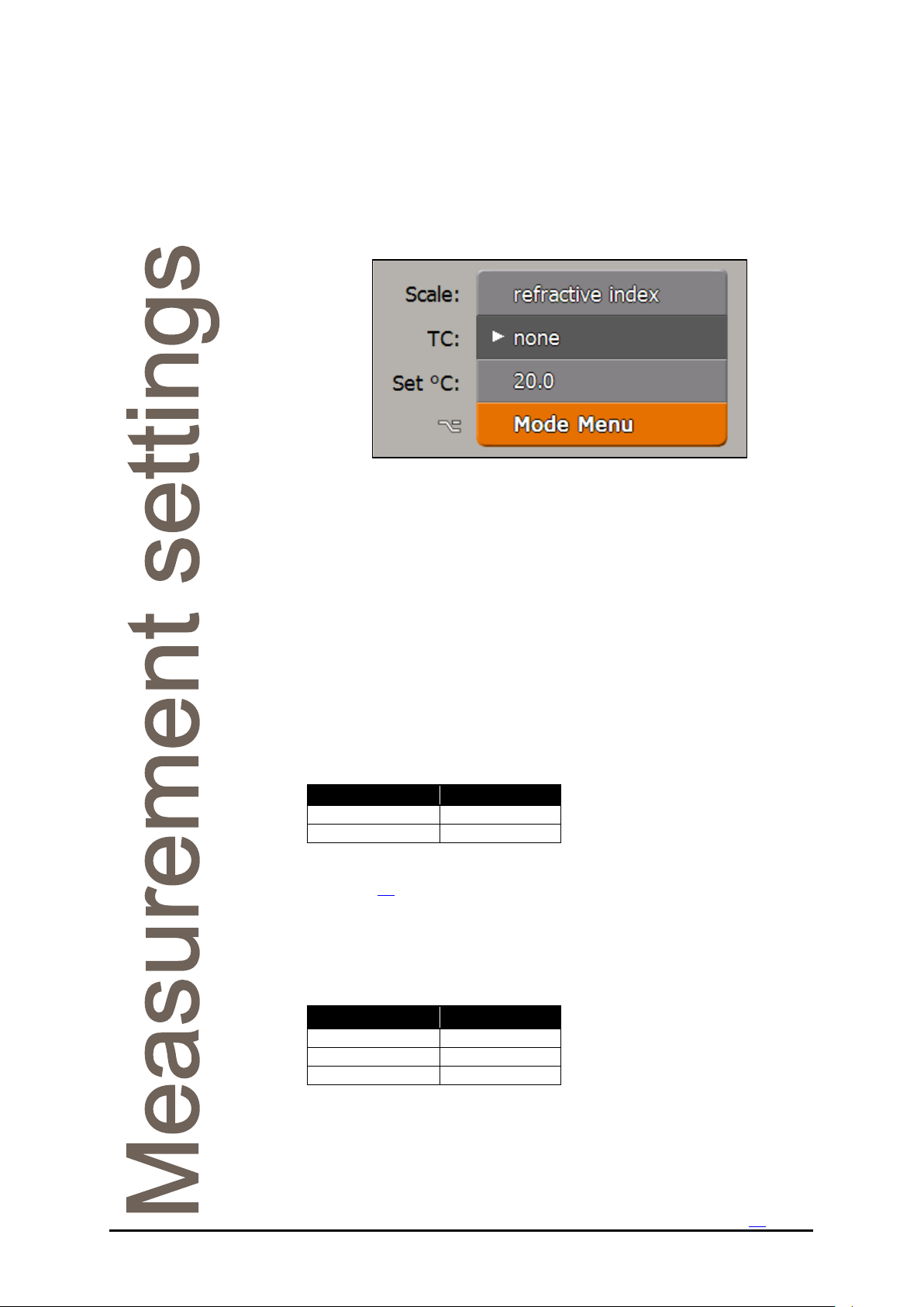
To change measurement settings press the orange Mode button. The
Mode Configuration is divided into two screens with Basic and Advanced
settings.
The Basic settings change the way a result is calculated, for example the
scale units and temperature compensation applied, and also allows
changes to temperature. The Basic settings are:
• Scale, Page 21
• Temp. Comp., Page 21
• Set Temp, Page 22
The Advanced settings allow the use of additional criteria to affect how a
measurement is taken and displayed. The Advanced settings are:
• Stability, Page 22
• Limits, Page 22
• Resolutions, Page 25
• Secondary Reading, Page 25
Once set, press the Quit button or Home button to return to the
Measurement Display. Changes to the Basic settings will be displayed on
the Reading Configuration section of the screen, ready for the next
reading.
Page 20 19-461’02 Rev. D September 2017 RFM300-T
Scale name
Scale ID
Refractive Index
ri
Brix
bx
TC name
TC ID
none
no
sugar
su
ag fluid
ag
Using the Reading Configuration Panel
Basic settings can be changed with the Reading Configuration Panel.
To change a setting, touch and hold the panel and an arrow will appear
next to the selected item. If the wrong item is selected, the user can slide
their finger up or down until the required item is highlighted.
When the arrow is next to the desired item, release the screen. The
options for the selected item will then be displayed.
Changing settings in this manner overwrites the settings in the Mode
Menu, a login may therefore be required if PINs are active.
Basic settings
The following settings can be changed in the Mode Menu, in each
Method or with the Reading Configuration Panel.
Scale
By default the available scales are:
Many other pre-installed scales, as well as custom scales, can be added,
see Page 53
.
RFM300-T 19-461’02 Rev. D September 2017 Page 21
Temp. Comp. (temperature compensation)
By default the available temperature compensation modes are:
Sugar compensation operates in accordance to ICUMSA in the range 10
to 40°C and has been extended to cover the range 5 to 70°C.
Ag fluid compensation can be used with Bellingham + Stanley’s range of
AG Fluid calibration materials, see the Accessories section.
Additional temperature compensations can be added, see Page 56
.

Set Temp (temperature control set-point)
The temperature control system in the instrument can be set over a wide
range of temperatures. In many situations, it is likely that all samples will
be measured at the same temperature, e.g. 20°C for a bottling plant or
70°C for a preserves factory.
Some manufacturers, who produce a range of different products for
different markets at one facility, may need to measure samples at more
than one temperature. However, temperature changes must be used with
care. Due to the time required for stabilisation it is not practical to
continually adjust the temperature set-point for every sample.
After changing the Set Temp, the instrument will inhibit measurement
until the system has stabilised and a Zero calibration has been carried
out (see Page 28
will be more practical if, say, all samples to be measured at 20°C were
carried out in a morning session and then those at 70°C in the afternoon.
The temperature of the stainless steel prism plate will be similar to
the temperature control set-point and so could become extremely
hot. Direct contact with skin should be avoided when applying
sample or cleaning the prism plate at temperatures above 50°C.
for information on Auto Zero). Changing the set-point
Advanced settings
Advanced settings can be changed in the Mode Menu or in the individual
Methods. They cannot be changed via the Reading Configuration Panel.
Stability
Stability sets conditions that must be met before a reading will be taken.
Stability can be set to:
• none
• delay
• repeatability
• SMART
Delay causes a wait period before measurements are initiated after
pressing the Read button. This delay provides a fixed time for the sample
to stabilise on the prism and to achieve thermal equilibrium throughout
the sample mass.
Page 22 19-461’02 Rev. D September 2017 RFM300-T
Loading...