

R
platinum db3A dual fuel cooker
Installation & User’s instructions
platinum db3A dual fuel - Natural Gas
(Liquid Petroleum gas convertible)
Note: This appliance is supplied for use with the category of gas
specified and can be converted to LP gas with the kit
provided.
1

Contents
Product Specification………………………………………………………………………………………….3
Introduction…………………………………………………………………………………………………..…4
Installation Instructions…………………………………………………………………………………….5-8
For Your Safety Never..……………………………………………………………………………………….9
For Your Safety Always………………………………………………………….…………………………..10
Know Your Cooker…………………………………………………………………………………………….11
Know Your Control Panel…………………………………………………………………………………….12
Timer Instructions………………………………………………………………………………………….13-17
Automatic Cooking (Large Oven)………………………………………………..…………………………18
Using the Hob……………………………………………………………………………………………….19-21
Main Multifunction Oven & Grill…………………………………………………………………………22-26
Small Conventional Oven / Storage & Reheating of Food……………………………………………..27
Main Multifunction Oven Cooking Guide………………………………………………………………28-29
Small Conventional Oven Cooking Guide…………………………………………………………………30
Temperature Conversion Scale………………………………………………………………………………31
Care & Cleaning……………………………………………………………………………………………..32-33
Is There Something Wrong With Your Cooker…………………………………………………………….34
Cooking Results…………………………………………………………………………………………………35
Service…………………………………………………………………………………………………………….36
2
Product Specification
Platinum db3A Technical Data
DIMENSIONS:- Height 900 – 915mm
Width 997mm
Depth 600mm (excluding door handles)
GENERAL
Gas connection Rp ½
Burner pressure Natural Gas – 1.0kPa
LPG Gas models – Propane 2.75kPa
Pressure test point Gas Regulator (Nat Gas) or Front Right Semi-Rapid hob burner
(see checking burner pressure)
Gas rate adjustment None
Aeration adjustment None
Electrical connection 4mm² cable 230 – 240V ac 50Hz
Total Heat Input (Gas) Natural Gas: 44.5 MJ/h
LPG – Propane: 38.4 MJ/h
Total Heat Input (Electric) 4.47 – 4.87kW
Multifunction Oven (Left Hand)
Oven Light Only 0.01 - 0.02kW
Fan Oven & Light 2.37 – 2.58kW
Conventional Oven & Light 2.04 – 2.22kW
Fan Grill (Closed Door) 2.43 – 2.65kW
Fan Only & Light (Defrost) 0.04 – 0.05kW
Grill (Full) (Closed Door) 2.41 – 2.62kW
Grill (Half) (Closed Door) 1.30 – 1.42kW
Conventional Oven (Right Hand) 2.04 – 2.22kW
BURNER
HEAT INPUT INJECTOR HEAT INPUT INJECTOR
Middle
(Ultra Rapid) / Wok
Front Left
(Rapid
Rear Left / Front Right
(Semi-Rapid)
Rear Right
(Auxiliary)
NATURAL GAS LPG - PROPANE
13.0 MJ/h 1.65mm 12.0 MJ/h 0.95mm
12.0 MJ/h 1.55mm 10.0 MJ/h 0.87mm
7.7 MJ/h 1.25mm 6.3MJ/h 0.69mm
4.1 MJ/h 0.90mm 3.8 MJ/h 0.53mm
3

Introduction
Your belling Cooker Thank you for purchasing a new belling platinum db3 cooker. Its stylish, practical
design will enhance your kitchen and make cooking a pleasure. It features a
large multifunction oven/Grill (Closed door), a small conventional oven, a storage
compartment, 5 gas hob burners and a utensil holder. There is also an electronic
clock/timer featuring a minute minder and automatic cooking facilities (large oven
only).
Even if you have used an electric or gas cooker before, it is important that
you read these instructions thoroughly before starting to cook, paying particular
attention to the installation and safety instructions.
Getting Help If you have any problems with installing, operating, or cooking with your belling
cooker, please check through these instructions thoroughly to make sure that
you have not missed anything. If you still need help, then please contact your
retailer or place of purchase.
Please quote the cooker model and serial number with all inquiries. This can be
found on the chassis behind the drop down storage compartment panel.
WARNING! For your own safety, make sure that these instructions on
installation, use and maintenance are followed.
We advise you to keep these instructions in a safe place for future reference.
If you sell or transfer ownership of this product, please pass on these Instructions
to the new owner.
Unpacking Unpack the components from inside the storage compartment.
Check that the following parts are present.
Meat / Grill pan with food support grid and detachable handle
Pan supports (3)
Pan Support Bridge
Multifunction oven shelves (2)
Conventional oven shelf
Baking Tray
Hob burners (5)
LP Gas Conversion kit
Literature
After unpacking your cooker, make sure that you remove all the packing from the
grill compartment / ovens and any stickers from the oven doors and hob.
Examine your cooker for any damage. If there is damage to your cooker or
anything is missing, please contact your supplier for advice.
4
Installation Instructions
Gas Safety
This appliance is
TO BE INSTALLED ONLY BY AN AUTHORISED PERSON
(Installation & accordance with the manufacturers installation instructions,
Use) Regulations local gas fitting regulations, the AGA Gas Installation Code, the Australian Gas
Installation code AG601/AS5601 and any other relevant statutory regulations.
Particular attention should be given to the relevant requirements regarding
ventilation.
Failure to install the cooker correctly could invalidate the warranty liability claims
and could lead to prosecution.
Where this appliance is installed in marine craft or in caravans, it shall NOT
be used as a space heater.
Space for Fixing Your cooker is heavy, so be careful when moving or positioning it. Do not try to
move the cooker by pulling on the doors or handles or control panel. The Belling
db92 is designed to 'slot-in' between 600mm deep cabinets, spaced at least
915mm apart. It can also be used freestanding, with a cabinet to one side, in a
corner setting or with its back to a wall. However it must not be situated with
either side closer than 50mm to a combustible wall or cupboard that is higher
than the cooker.
in
The wall behind the cooker and 450mm above and across the width of the
cooker, should be of an incombustible material or easy clean surface such as
ceramic tiles. Please note, when positioning your cooker against a wall, ensure
there is sufficient clearance for the screw heads on the back panel.
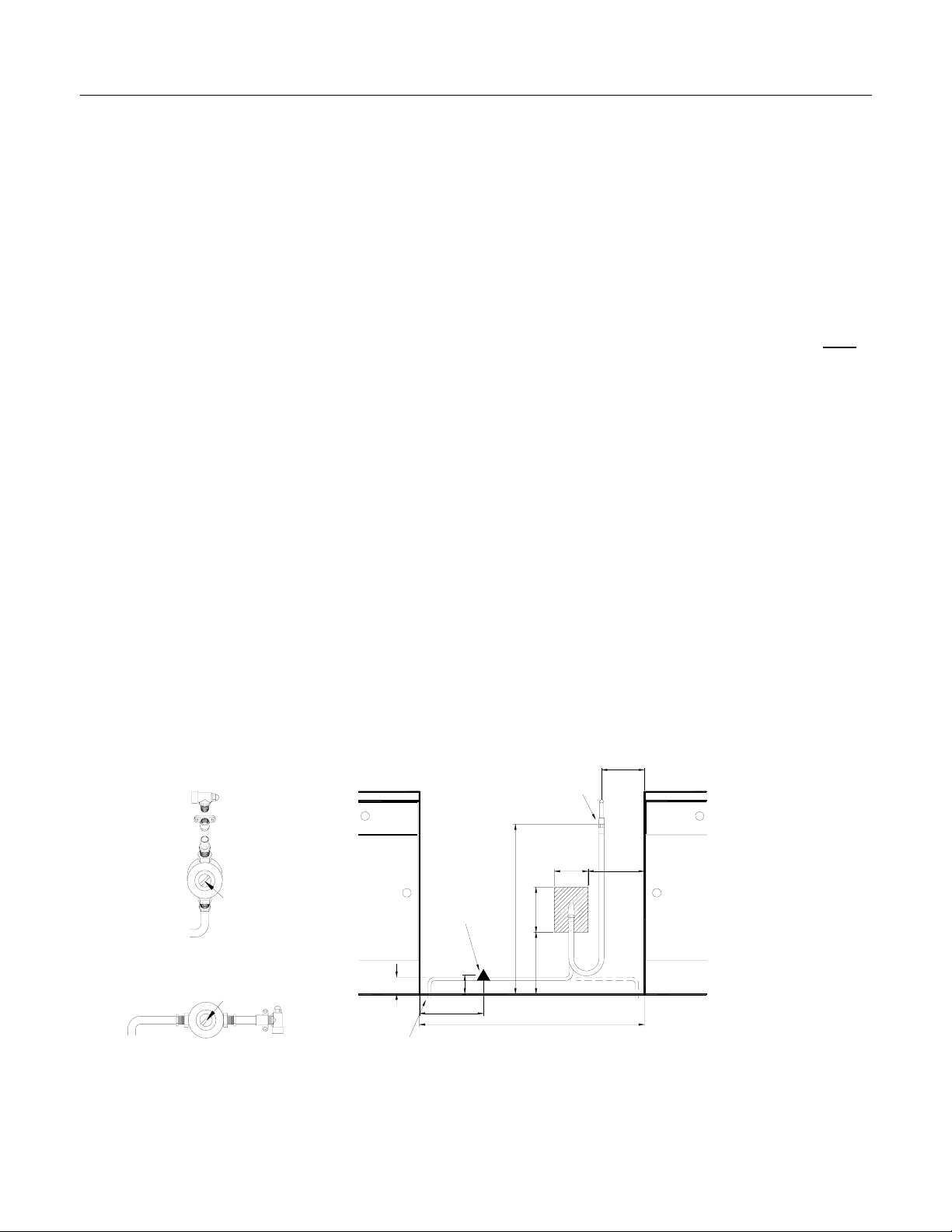
This appliance is designed not to project in front of standard 600mm worktops
(excluding handles). To achieve the best fit the cooker must be pushed against the
wall. If the wall mounted adapter back-plate (Fig.1) is to be fitted behind the
appliance then the suitable area for this fitting is shown as the area in (Fig.2).
Fig. 1
Fig. 2
150
MAINS INLET ON APPLIANCE
150
250
GAS REGULATOR
(Natural Gas Only
ELECTRICAL CONNECTION
755
200
VERTICAL PIPEWORK OPTION
GAS REGULATOR
(Natural Gas Only
HORIZONTAL PIPEWORK OPTION
275
285
85
1000
75
MAX
OR COOKER TO SIT FLUSH WITH THE REAR WALL :-
AS PIPE MUST NOT BE MORE THAN 75mm ABOVE THE FLOOR (In either direction)
R PROJECT MORE THAN 40mm FROM THE REAR WALL
NOTE: The adaptor backplate requires chasing into the wall if it protrudes more than 40mm. This is to
allow the cooker to be pushed back to the wall.
5
Installation Instructions
Any overhanging surface or cooker hood should be at least 760mm (30") above
the cooker hob. We do not recommend positioning the cooker below wall
cupboards, as the heat and steam from the cooker may cause damage to the
cupboard and its contents.
Excess steam from the oven, vents out at the top back edge of the cooker, so
make sure that the walls behind and near the cooker are resistant to heat, steam
and condensation.
Levelling Your cooker must stand on a flat surface so that when it is in position the hob is
level. The cooker is fitted with rear wheels and will slide into position easily.
Movement of your cooker is most easily achieved by lifting the front, as follows.
Open the oven doors sufficiently to allow a comfortable grip on the underside front
edge of the oven roofs, avoiding grill elements or oven furniture.
Adjust the cooker at the rear to the required height, using the 2 jacking screws
situated behind the rear access cover and secure with the lock-nuts. Position the
cooker and adjust the height at the front with the 2 jacking screws situated at the
front underside. Check that the cooker is level by using a spirit level (adjusting the
jacking screws if necessary). It is important that the cooker is stable and level for
the overall cooking performance.
Caution NOTE: This appliance should not be installed on a platform.
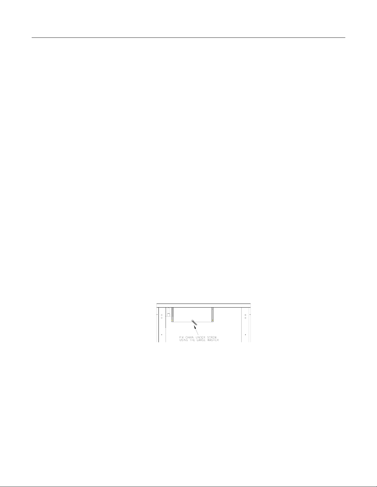
Stability Chain
The cooker must be fitted with a stability device such as a proprietary stability
chain (supplied) as shown in Figure 3 and firmly secured to the fabric of the
building. Any leaflet included with the chain should be read in conjunction with the
following instructions.
Whatever the position, remember to leave enough room for the cooker to be pulled
out for cleaning and service.
Fig.3
6

Installation Instructions
Connect to Gas Supply Means of isolation shall be provided at the supply point by either an approved
quick connect device or a type1 manual shut off valve. The outlet of the quick
connect device shall be at, or below, the horizontal position.
Connection to the cooker should be made using the supplied AGA certified hose
assembly and regulator (Natural Gas only).
Note: Max length of hose = 900mm
The temperature rise of areas at the rear of the cooker that are likely to come
into contact with the flexible hose do not exceed 70°C.
1
/2 elbow is fitted to the cooker.
A Rp
If the position of the wall connection is within 250mm of the oven inlet, the loop of
hose will give maximum movement to the cooker.
A restraining chain or wire of adequate strength is to be fixed to the appliance and
the wall within 50mm of each connection point. The length of the chain or wire is
not to exceed 80% of the length of the hose assembly. The restraining chain or
wire is to prevent stress being imparted onto the hose assembly when the cooker
is moved out of its normal operating position.
After installation, check for soundness.
The burner pressure is tested at the hob burner situated rear/left.
With reference to the user instructions:
1 Check that the hotplate burners ignite correctly and burn with a steady flame.
2 Check for a steady flame at the low (small flame symbol) setting.
3 Instruct the user on the operation of the cooker.
Checking Burner Pressure The burner pressure of the appliance can be checked at the Gas regulator
(Nat Gas), or the front Right Semi-Rapid hob burner (the adaptor supplied will be
required).
When checking at the front right Semi-Rapid burner, remove the burner jet and
screw in the adaptor. Connect the test equipment and ignite the Rapid burner
(Front left) on maximum setting. Pressure should be as stated on the data badge
(adjust the pressure if required). Remove the adaptor and replace the jet in the
burner (Rapid).
IMPORTANT:
Ensure the pressure adaptor is retained by the householder for use by future
authorized service personnel.
Bypass Adjustment
The appliance is factory set for Natural Gas. All bypass screws are preset to suit
and should only require adjustment, by an authorized person, when the appliance
is being converted to Propane gas (Refer to Conversion Instructions). If
adjustment is required, the adjusting screw is situated down the center of each gas
tap spindle and is adjusted, only by an authorized person, with the aid of a small
flat-headed screwdriver.
Clockwise = Reduce rate
Anti-clockwise = Increase rate
If the appliance cannot be adjusted to perform correctly, then please contact your
sales agent shown at the rear of these instructions or your local gas authority.
7
Installation Instructions
Connecting to Electrical For your own safety, we recommend that your cooker is installed by a
Supply competent person. The cooker should be installed in accordance with
AS/NZS 3000:2000
WARNING: THIS APPLIANCE MUST BE EARTHED!
The cooker must be connected to the correct electrical supply as stated on the
rating plate, through a suitable cooker control unit incorporating a double pole
switch having a contact separation of at least 3mm in all poles, adjacent to (but not
above) the cooker. We recommend that the cooker circuit is rated to 30 Amps.
We also recommend that 4mm² P.V.C. (minimum 2.5mm² - maximum 6.0mm²)
Insulated twin and earth cable is used to connect the cooker control unit.
IMPORTANT:
For access to the mains terminal block and for supply cable connection, it is
necessary to remove the access cover situated at the bottom of the back panel.
No part of the appliance will operate unless the main control unit is switched ON.
The live and neutral positions are marked with the letters L and N respectively,
marked in front of the terminal block. The earth terminal is marked by the earth
symbol.
Allow sufficient cable length for the cooker to be pulled out for cleaning, but do not
let it hang closer than 25mm (1”) to the floor. The cable can be looped if
necessary, but make sure that it is not kinked or trapped when the cooker is in
position. Secure the mains cable using the cable clamp.
Connect the mains cable as follows:Live to terminal L.
Neutral to terminal N
Earth to the earth stud.
Before Cooking
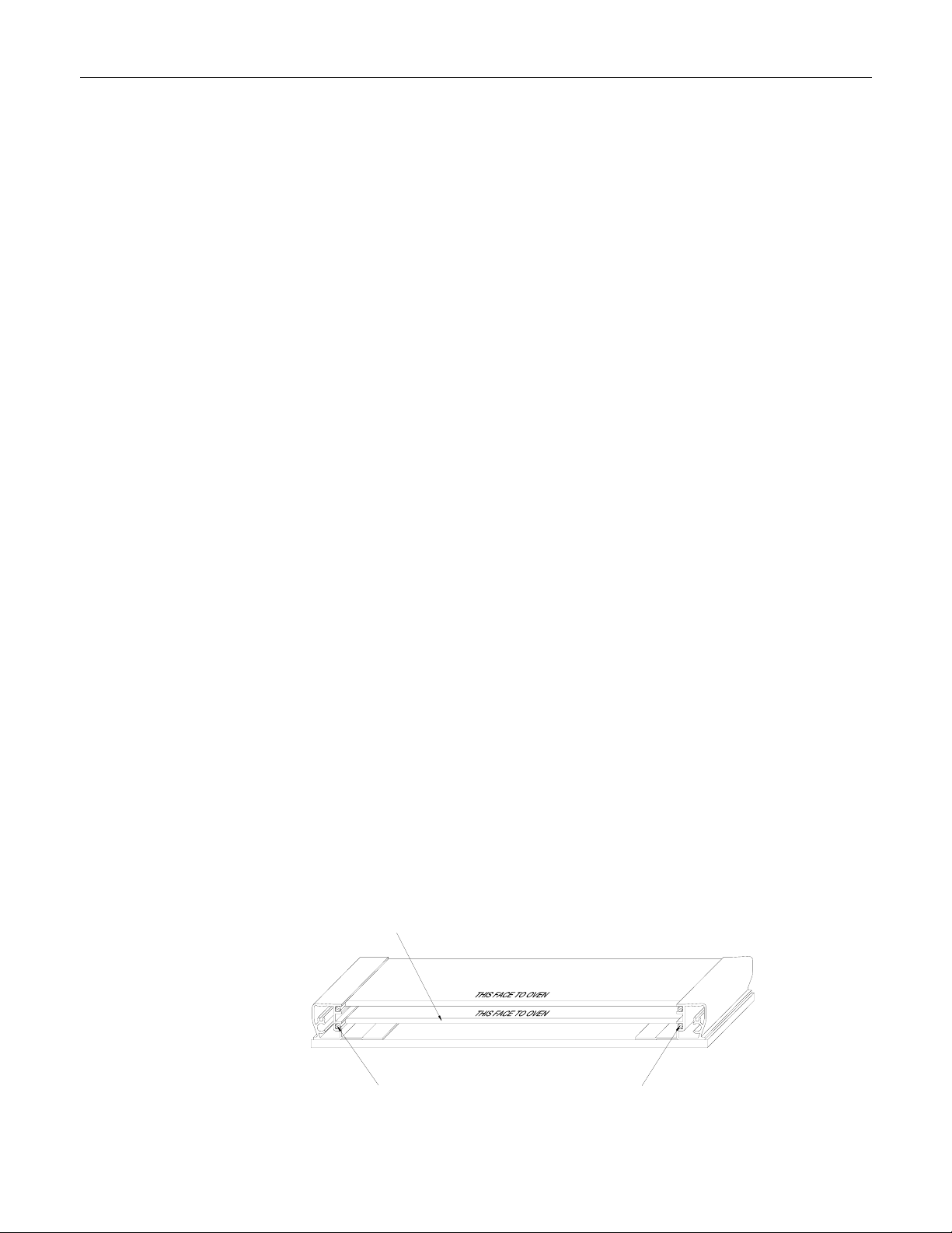
Additional Protective An additional protective means to avoid contact with high temperatures on the
Means oven doors is available. An extra inner door glass is provided to make the door
Before you cook for the first time, we recommend that you switch on each element
in turn to burn off any odours remaining from manufacture.
assembly triple glazed, thus reducing temperatures on the door front. This part
should be fitted when young children are likely to be present.
The kit is available as an optional extra from the Belling Agent as listed at the
rear of the instructions.
Quote Reference: DK0001
Inner door glass slides into position
Screw (2) Grubscrews into the base of the extrusions
into the channels as shown
8

For Your Own Safety
When used properly your Belling Cooker is completely safe, but as with any cooker there are some precautions
you must take in its use.
NEVER
• Never allow anyone except an authorized Belling Service Agent to service or
repair your cooker.
• Never remove any part of the cooker other than those intended in normal use, or
attempt to modify the cooker in any way.
Never use the cooker for commercial catering. It is designed for domestic use.
•
• Never allow young children to operate or play with the cooker.
• Never use a chip pan or deep fat fryer more than
frying and do not leave a fryer unattended while cooking.
• Never line the shelves, floor, or sides of the ovens or grill with aluminum foil as
overheating and damage may result.
• Never place anything which might catch fire, such as towels or tea towels, near to
the burners or over the flue outlet even when the cooker is not in use.
• Never use an asbestos mat, trivet or rack of any kind under pans on any hotplate.
• Never store anything which might catch fire in the oven, grill compartment or
storage compartment.
• Never allow aluminum foil or plastic to touch any hotplate when it is hot.
• Never store flammable liquids, aerosols, etc. in adjacent cabinetry.
• Never dry clothes or place other items over or near to the hotplate or oven or grill
doors.
• Never use large preserving pans or fish kettles across two hotplates as this will
damage the hob.
• Never use cooker as a room heater.
• Never wear garments with long flowing sleeves whilst cooking.
• Never leave burners lit when not in use.
• Never use the hotplates with the burner caps removed.
Never use badly designed or misshapen pans which may be unstable.
•
• Never allow pan handles to stick out beyond the hotplate (where they can be
knocked) or over another burner.
• Never store flammable materials in the storage drawer
MPORTANT! DO NOT SPRAY AEROSOLS IN THE VICINITY OF THIS COOKER WHILE IT IS
IN OPERATION
1
/3 full of oil, or use a lid while
IF YOU SMELL GAS turn off all gas controls on the hob, open windows and turn
off gas supply at the mains. Do not operate any electrical switches and contact
your local gas supplier immediately.
9

ALWAYS
For Your Own Safety
• Always make sure you understand the controls prior to use.
• Always take care when touching any part of the cooker that may be hot. Use good
quality dry oven gloves when removing or replacing food or dishes.
• Always stand back when opening the oven door to allow any build-up of heat or
steam to disperse.
• Always keep the oven and grill doors closed when not in use to prevent accidents.
• Always make sure that the roof, side and back panels, and shelves are fitted
correctly before using the oven or grill.
• Always keep your cooker clean, as a build-up of grease or fat from cooking may
be a fire hazard.
• Always switch off at the mains supply before cleaning your cooker.
• Always supervise children and pets, particularly when grilling, as exposed parts of
the grill may become hot.
• Always place pans centrally over the hotplate burners and make sure that they are
stable.
• Always keep handles away from the edge of the hob and any other burners. For
added safety you should consider using a suitable hob guard.
• Always make sure that all the controls are switched off when you finish cooking.
• Always remember that your cooker may stay hot for a time even after you have
finished cooking.
• Always keep ventilation slots at the rear of the cooker clear of obstructions.
10
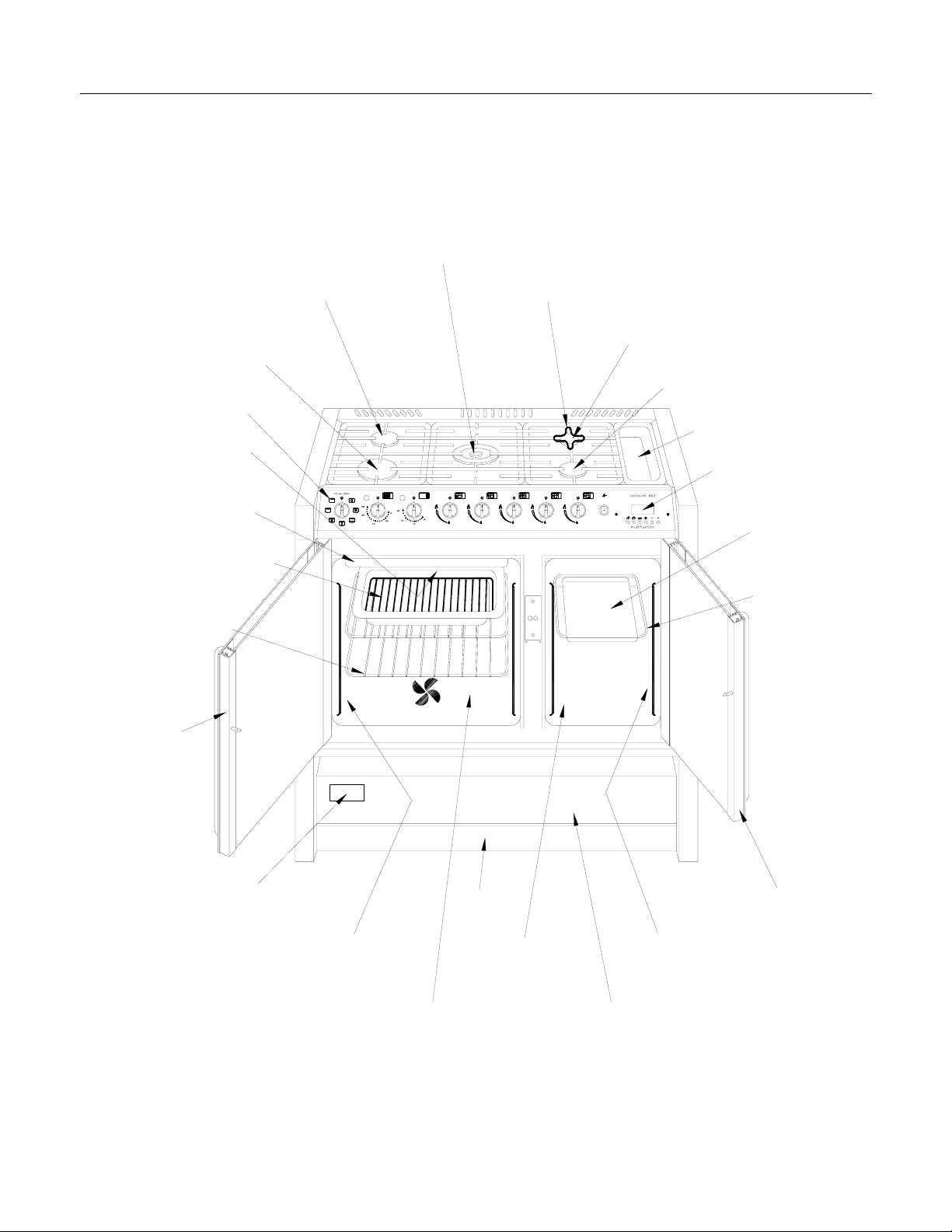
Know Your Cooker
Centre hotplate
(Wok-Triple Ring)
Rear left hotplate
(Semi-Rapide)
Front left hotplate
(Rapide)
Control panel
Pan Bridge Support
Rear right hotplate
(Auxiliary)
Front right hotplate
(Semi-Rapide)
Electric grill
(Closed door)
Cookclean roof liner
Meat/grill pan c/w
food support grid &
detachable handle
(Not shown)
2 Oven shelves
Easyfit
main oven
glass door
Utensil holder
Electronic digital timer &
large oven programmer
Baking tray
1 Oven shelf
multi-function
Rating label on chassis
(Behind storage panel)
Cookclean side & rear panels
Large Timed Electric Multifunction Oven
PLinth
Small electric
conventional oven
Cookclean side panels
Drop down storage panel
Easyfit small oven glass door
11
 Loading...