

Belling G706, G707, G709, G708, DB60 Installation And User Instructions Manual
Slot-in Gas Cooker
INST ALLATION AND USER
INSTRUCTIONS
Model Number
G706
G707
G708
G709
DB60
This appliance is supplied for use with Natural gas
G20 only and cannot be converted to any other gas.
2
G141
CONTENTS
The appliance was designed and made in accordance with the European standards listed below:
• EN 30-1-1, EN 30-2-1 and EN 437 plus subsequent amendments (gas)
• EN 60 335-1 and EN 60 335-2-6 (electrical) plus relative amendments
The appliance complies with the prescriptions of the European Directives as below:
• 73/23 + 93/68 EC concerning electrical safety (BT).
• 89/336 + 92/31 + 93/68 EC concerning electromagnetic compatibility (EMC)
• 90/396 + 93/68 EC concerning gas safety.
Oven accessories that could come into contact with foodstuffs are made with materials that comply
with the provisions of the 89/109 EC directive dated 21/12/88.
INTRODUCTION page 3
INSTRUCTIONS FOR THE INSTALLER pages 4-10
FOR YOUR OWN SAFETY page 11
KNOW YOUR COOKER pages 12-13
USING THE GAS HOB page 14
USING THE GAS HOB - GENERAL NOTES page 15
GRILLING page 16
GRILLING - GENERAL NOTES page 17
USING THE MAIN OVEN page 18
MAIN OVEN COOKERY NOTES pages 19-20
USING THE TOP OVEN - DB60, G707 and G 708 only page 21
TOP OVEN COOKERY CHARTS - DB60, G707 and G 708 only page 22
CLEANING AND MAINTENANCE pages 23-24
IS THERE SOMETHING WRONG WITH YOUR COOKER? pages 25-26
SERVICE page 27

3
G141
INTRODUCTION
Your Belling Cooker
Thank you for purchasing a new Belling gas Cooker . Its stylish and practical design will enhance your
kitchen and make cooking a pleasure. Dependant on model, it features a large main oven with a light,
a separate top oven (DB60, G707 and G708 only), grill and a gas hob, all with push button ignition.
Some models also feature a clock which features a minute minder and a toughened glass lid with
safety shut off valve.
Even if you have used a gas cooker before, it is important that you read these instructions thoroughly
before starting to cook, as there may be many new features not featured on your previous cooker.
Pay particular attention to the installation and safety instructions.
Getting Help
If you have any problems with installation, operating or cooking with your Belling cooker please
check through these instructions thoroughly to make sure that you have not missed anything. If you
still need help, then please contact (including a daytime telephone number if possible):
Customer Care Centre
Belling Appliances
Stoney Lane
Prescot
Merseyside
L35 2XW
Belling Customer Care Centre Tel: 0151 432 7999
Please quote the cooker model and serial number with your enquiries. This can be found on the rating
label, positioned on the rear panel of the cooker
WARNING! For your own safety, make sure that these instructions on installation, use and
maintenance are followed.
We advise you to keep these instructions in a safe place for future reference.
If you sell or transfer ownership of this product, please pass on these instructions to the new owner.
Note: the pictures shown in the figures in this handbook are purely indicative.
4
G141
INSTRUCTIONS FOR THE INSTALLER
TECHNICAL INFORMATION
•All installation and maintenance must only be
carried out by qualified personnel. The manufacturer
cannot be held responsible for any damage to
persons or property resulting from an incorrect
installation of the appliance.
• The appliance must only be used for its original
purpose, that is, cooking for domestic use.
• The manufacturer cannot be held responsible for
any damage to persons or property resulting from
an incorrect installation, maintenance or use of the
appliance.
• The electrical safety of this appliance is only
guaranteed if it is correctly connected to a suitable
earth system, as prescribed by the electrical safety
standards. The manufacturer disclaims all
responsibility if these instructions are not followed.
Should you have any doubts, seek the assistance
of a qualified person.
• Before connecting the appliance ensure that the
rating plate data corresponds to that of the gas and
electricity supply .
• The safety and automatic adjustment devices of
the appliance may, during its life, only be modified
by the manufacturer or duly authorised supplier.
UNPACKING Y OUR COOKER
• Remove all packaging before use and check to
make sure that the appliance is in perfect condition.
If you have any doubts do not use the appliance
and call your supplier for advice.
• Do not move the appliance using the handles.
Some parts on the appliance are protected by a plastic
film. This protective film must be removed before the
appliance is used. We recommend carefully slitting the
plastic film along the edges with a sharp knife or pin.
The packaging materials should carefully
discarded and not left within easy reach of
children, as they are a potential safety hazard.

5
G141
INSTRUCTIONS FOR THE INSTALLER
Prior to installation, ensure that the local distribution
conditions (nature of the gas and gas pressure) and the
adjustment conditions are compatible. The factory set
adjustment conditions for this appliance are stated on
the rating label, which is fitted to the back panel of the
appliance.
This appliance is not designed to be connected to a
combustion products evacuation device. It must be
installed and connected in accordance with current
installation regulations. Particular attention should be
given to the relevant requirements regarding ventilation.
This appliance is factory set to burn NATURAL GAS (G20),
category I2H+ (GB, IE) at 20mbar ONLY and cannot be
used on any other gas category.
GAS SAFETY (INSTALLATION & USE)
REGULATIONS
It is the law that all gas appliances are installed by
competent persons in accordance with the current
edition of the above regulations. It is in your interest
and that of safety to ensure compliance with the law.
In the UK, CORGI registered installers work to safe
standards of practice.
The cooker must also be installed in accordance with
BS 6172: 1990.
Failure to install the cooker correctly could invalidate
the warranty liability claims and could lead to
prosecution.
LOCATION
The cooker may be located in a kitchen, kitchen/diner
or a bed-sitting room, but not in a room containing a
bath or shower. The cooker must not be installed in a
bed-sitting room of less than 20 m
3
.
PROVISION FOR VENTILATION
The room containing the cooker should have an air
supply in accordance with BS 5440:Part 2: 1989.
The room must have an opening window or equivalent;
some rooms may also require a permanent vent. If the
room has a volume between 5 and 10 m
3
, it will require
an air vent of 50 cm
2
effective area unless it has a door
which opens directly to outside. If the room has a volume
of less than 5 m
3
, it will require an air vent of 100 cm
2
effective area. If there are other fuel burning appliances
in the same room, BS 5440: Part 2: 1989 should be
consulted to determine air vent requirements.
6
G141
INSTRUCTIONS FOR THE INSTALLER
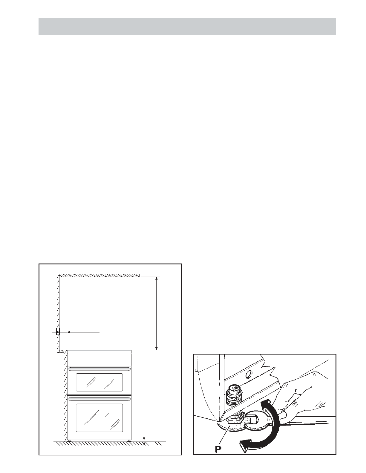
POSITION
The appliance must not be installed on a compressible
floor covering, i.e. carpet or carpet tiles. Care must be
taken to ensure a minimum air gap of 10mm is
maintained between the floor and the underside of the
appliance.
The appliance should be positioned in good light and
free from draughts. Any shelf or cupboard of combustible
material should be at least 750mm above the hob top,
a greater clearance is desirable if discoloration is to be
avoided, otherwise the shelf etc. should be protected.
In accordance with the gas standards, the gas
appliances can be installed as “class 2 subclass 1”
(recessed) and, as such, must comply with the
clearances specified in figure.
The rear wall and surfaces adjacent to or surrounding
the appliance must be able to resist a temperature rise
of 65°C. We recommend fitting ceramic tiles to protect
the surrounding surfaces.
NOTE: When installing the appliance adequate space
must be provided to allow the glass lid (where fitted) to
be opened to its fullest extent.
LEVELLING THE COOKER
• It is important that the cooker is placed on a firm
level surface and that the feet, are adjusted to
ensure that the cooker is perfectly level. An
unlevelled cooker can affect the cooking results.
To level the cooker simply adjust the feet (P) (See
diagram below) screwing up or down as required.
By turning these feet you can align the cooker height
with the adjacent work surfaces.
• The cooker is fitted with two spacers placed at the
rear part of the hob top, which ensures a minimum
distance between the appliance and the rear wall.
They must not be removed.
NOTE: Under no circumstances must the feet be
removed.
50 mm
750 mm
Min. 10 mm
7
G141
INSTRUCTIONS FOR THE INSTALLER
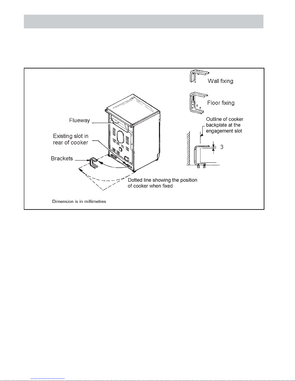
STABILITY BRACKET
We recommend a stability bracket is fitted to the cooker . The type shown in the diagram below can be purchased
from most plumbers merchants and DIY shops.
Note: The power supply cable must be positioned so that no part of the cable can come into contact with any
surface which could reach temperatures in excess of 75°C.
8
G141
INSTRUCTIONS FOR THE INSTALLER
ELECTRICAL CONNECTION
The electrical connection must be carried out in
accordance with the current standards and laws
in force and by a qualified electrician.
WARNING!!: This appliance must be earthed.
This appliance operates from a 3 pin, 13 amp plug,
supplied fitted to the appliance. The voltage ra ting is
230 Volt and should be protected by a 5 amp fuse in the
plug. Should the fuse require replacement, it must be
replaced with a fuse rated at 5 amp approved to BS1362.
Should this plug not fit the socket outlet in your home it
should be cut off and replaced with a suitable plug as
outlined below.
NOTE: The removed plug cannot be used for any other
appliance and should therefore be properly disposed of
and not left where children might find it and plug it into
a supply socket - with the obvious consequent danger.
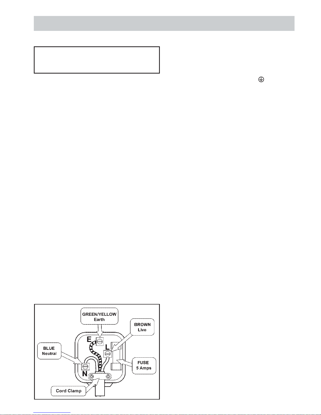
Important: The wires in the mains lead on this appliance
are coloured in accordance with the following code:
Green and Yellow = Earth
Blue = Neutral
Brown = Live
As the colours may not correspond with the markings
identifying the terminals in your plug, proceed as follows:
• The green and yellow wire must be connected to
the terminal in the plug, which is marked with the
letter E or with the earth symbol or coloured
green and yellow.
• The blue wire must be connected to the terminal
marked with the letter N or coloured black.
• The brown wire must be connected to the terminal
marked with the letter L or coloured red.
9
G141
INSTRUCTIONS FOR THE INSTALLER
GAS CONNECTION
IMPORTANT! This appliance is supplied for use on
NATURAL GAS ONLY and cannot be converted for use
on any other gas.
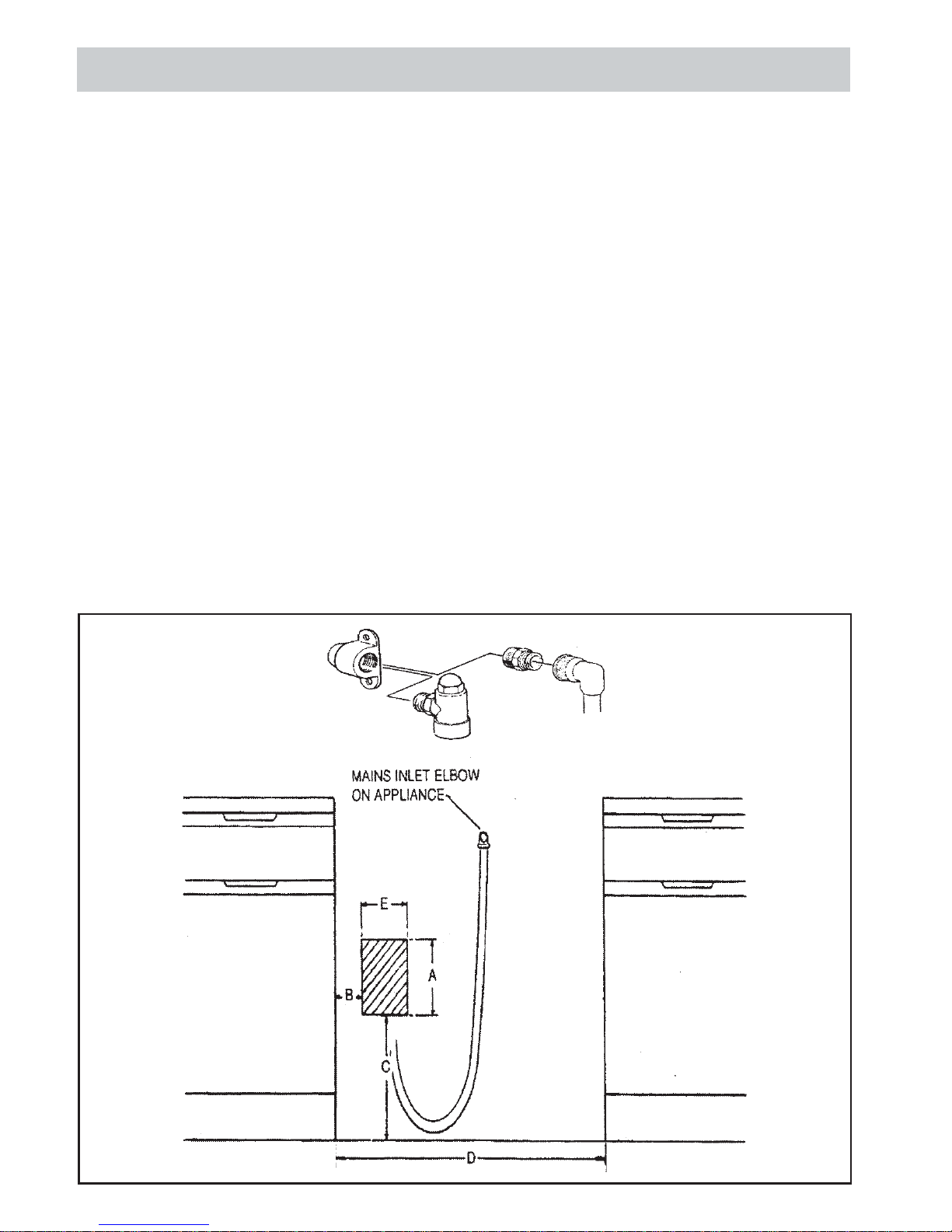
CONNECTING TO GAS SUPPLY
The cooker is designed to match the depth of standard
600mm worktops. An adaptor backplate should,
therefore, be fitted within the shaded area shown to
allow the cooker to be pushed fully to the wall.
Connection to the cooker should be made with an
approved appliance flexible connection to BS 669. A
length of 0.9 to 1.25 m is recommended. The length of
hose chosen should be such that when the cooker is in
situ, the hose does not touch the floor.
The temperature rise of areas at the rear of the cooker
that are likely to come in contact with the flexible hose
do not exceed 70ºC
A=200mm (7 /8”)
B=100mm (4”)
C=330mm (13”)
D=605mm (23
/4”)
E=150mm (6”)
7
3
 Loading...