


BE807
BE811
Integrated fridge/freezer
INSTALLATION AND USER INSTRUCTIONS
Instructions for Use
1
Integrated fridge/freezer
Thank you for purchasing a Belling product.
Please read this instruction book thoroughly before attempting to use the
product.
Please read these instructions carefully before installing or using this
appliance.
This appliance should be mounted and installed in compliance with
these instructions, current standards and regulations.
The electrical connection should be carried out by a suitably qualified
electrician.
Choosing the Right Place
Place the appliance in a dry and regulariy ventilated room. The allowed
ambient temperature for the appliance is from +16°C to +32°C.
In case the appliance is exposed to temperatures lower than +16°C, the operation
of the refrigerator is normal, yet the temperature in the freezing compartment is
raised which shortens the storage time of the frozen foods. Never place the
appliance near heat emitting devices (e.g. cooker, radiator, water heater or similar
devices) and do not expose it to direct sunlight.
Installation Dimensions and
Required Air Circulation 3
Changing the Direction of
Opening the Door 4-5
Installing the Appliance 6-7
Connection to the power supply 8
User Instructions 9
Before Use 10-12
2
Description of the Appliance 13-14
Operation Control 15
Use 16-19
Maintenance and Cleaning 20-21
Trouble-Shooting Guide
Calling for Service Back Cover
Instructions for Use
22-23
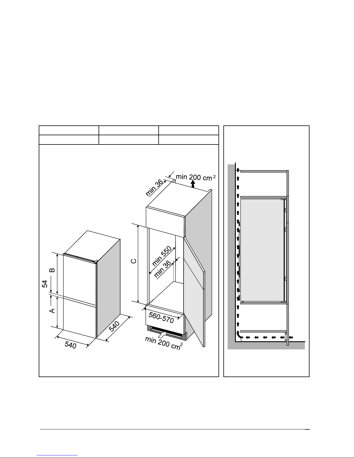
Installation Dimensions and Required Air Circulation
The rear wall of the appliance gets warm during the operation of the
appliance and water evaporates from the drain pan on the
compressor. You must therefore provide for adequate air circulation
on the rear of the appliance.
• At the base of the kitchen unit intended for building in the integrated
appliance, there should be at least 200 cm² free space, for
adequate air circulation.
• On the upper part of the appliance the air comes out, so do not
cover the opening for the outflow air.
A (mm) B (mm) C (mm)
846 840 1775-1780
Instructions for Use
3

Reversing the door opening
If you find the door opening direction of your appliance inconvenient,
you can reverse it. The necessary holes on the opposite side of the
appliance cabinet have been made in the factory and plugged.
• Remove the top hinge cover of the refrigerator door. Remove the
door by unscrewing the hinge (the door is supported only by the
bottom hinge) and remove the hinge washer.
• Unscrew the top fixing strip, move it to the opposite side of the
appliance and fasten it.
• Unscrew the bottom hinge and washer of the freezer door and
remove the lower door.
• Unscrew the top hinge of the freezer door and the bottom hinge of
the refrigerator door.
• Remove the corner caps from the door and reposition them (instead
of the corner cap with a hole insert the one without it, and vice
versa).
• Take off the washer from the bottom hinge of the freezer door (by
turning it in clockwise), pull out the bottom hinge pivot and fit into
opposite side.
• Put the freezer door on the bottom hinge.
• Turn the bottom hinge of the refrigerator door by 180°, insert the
hinge and the washer into the hole of the corner cap on the freezer
door and fasten it. Use the same procedure for the top hinge of the
freezer door and screw it on the opposite side of the upper door. Put
the washer and the upper door on the hinge.
• Screw the top hinge of the refrigerator door and replace the cover.
• Reposition the slide guides on the opposite sides of both doors.
• Plug the remaining holes with decorative caps.
• After you have reversed the door, check if the magnetic gasket seals
correctly. It must not be creased and must seal all around the door.
4
Instructions for Use
1 Top hinge cover of the refrigerator door 7 Bottom hinge of the freezer door
2 Top hinge of the refrigerator door 8 Bottom hinge pivot of the freezer
3 Top fixing strip door
4 Bottom hinge of the refrigerator door 9 Slider guide
5 Top hinge of the freezer door 10 Corner cap with a hole
6 Washer 11 Corner cap without a hole
Instructions for Use
5

Installing the Appliance
WARNING
Before mounting the appliance into the kitchen unit, disconnect the
power supply and set the thermostat knob to STOP (0) position.
• Push the appliance for some 38 mm into the kitchen unit and allow at
least 4 mm free space on both sides between the appliance and the
side walls of the kitchen unit (Fig. 1).
• Widely open both the doors and put them together with the door of
the kitchen unit. The procedure is as follows:
− Put together the appliance door and the door of the kitchen unit
(Fig. 2).
− Insert the slides into the guides and fix them on the kitchen unit
door some 15 mm from the edge, using the A 4 x 12 screws
(Fig. 3).
− Remove the slide guides and separate the appliance door from the
door of the kitchen unit.
− Fix the slides and be careful not to move them while fixing (Fig. 4).
− Fix the slide guides to the original position.
− Close the door and check the gasket (it should not be creased).
The door should open and close smoothly.
• Fix the appliance into the kitchen unit. On the upper side, fix the
three screws A 4 x 12 through the rail and on the lower side with two
screws A 4 x 16, through the lower hinges. Drill holes, ø 3 x 5
(Fig. 5).
• Seal the gap on the opposite side of the hinge with the enclosed seal
(Fig. 6).
6
Instructions for Use
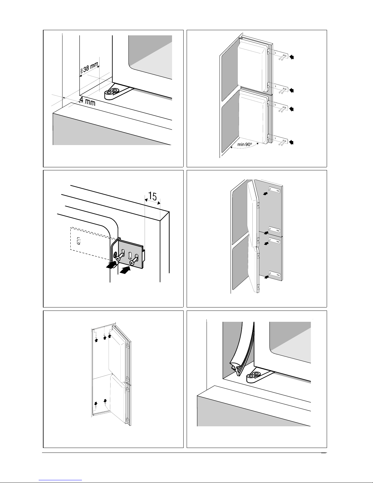
Fig. 1 Fig. 2
Fig. 3 Fig. 4
Fig. 5 Fig. 6
Instructions for Use
7

Connection to Power Supply
Connect the appliance with the cable and plug to a suitable 13 amp socket
which is properly earthed.
Required nominal voltage and frequency are indicated on the rating plate. The
connection to the mains supply and earthing have to be made according to
current standards and regulations. The appliance resists temporary voltage
tolerance up to -15 to +10 %.
If the fitted plug is not suitable for your socket outlet, then it should be cut off
and disposed of safely in order to avoid a possible shock hazard. A suitable
plug of 13 amp or 15 amp rating should then be fitted to the cable.
The wires in the mains lead are coloured in accordance with the following
code:
BLUE NEUTRAL
BROWN LIVE
GREEN AND YELLOW EARTH
1 The GREEN AND YELLOW wire must be connected to the terminal
in the plug which is marked with the letter E or by the earth symbol
or coloured green or green and yellow.
2 The BLUE wire must be connected to the terminal which is marked
with letter N or coloured black.
3 The BROWN wire must be connected to the terminal which is
marked with the letter L or coloured red.
8
Instructions for Use
 Loading...