

Belling 864 Installation And User Instructions Manual

2
CONTENTS
INTRODUCTION page 3
INSTRUCTIONS FOR THE INSTALLER pages 4-10
FOR YOUR OWN SAFETY page 11
KNOW YOUR COOKER pages 12-13
OVEN TIMER OPERATION pages 14-15
USING THE GAS HOB page 16
USING THE GAS HOB - GENERAL NOTES pages 17
GRILLING page 18
TOP OVEN COOKERY NOTES page 19
TOP OVEN COOKERY CHARTS page 20
MAIN OVEN COOKERY NOTES pages 21-22
MAIN OVEN COOKERY CHARTS page 23
CLEANING AND MAINTENANCE page 24
IS THERE SOMETHING WRONG WITH YOUR COOKER? pages 25-26
SERVICE page 27
The appliance was designed and made in accordance with the European standards listed below:
• EN 30-1-1, EN 30-2-1 and EN 437 plus subsequent amendments (gas)
• EN 60 335-1 and EN 60 335-2-6 (electrical) plus relative amendments
The appliance complies with the prescriptions of the European Directives as below:
• 73/23 + 93/68 EC concerning electrical safety (BT).
• 89/336 + 92/31 + 93/68 EC concerning electromagnetic compatibility (EMC)
• 90/396 + 93/68 EC concerning gas safety.
Oven accessories that could come into contact with foodstuffs are made with materials that comply
with the provisions of the 89/109 EC directive dated 21/12/88.
G83

Your Belling Cooker
Thank you for purchasing a new Belling Dual Fuel Cooker . Its stylish and practical design will enhance
your kitchen and make cooking a pleasure. Dependant on model, it features a large electric main fan
oven with a light, separate top oven and a grill. The hob features four gas burners with push button
ignition. Some models also feature a clock/timer with minute minder and an automatic main oven
switch on and off function as well as a toughened glass lid with safety shut off valve.
Even if you have used a gas or electric cooker before, it is important that you read these instructions
thoroughly before starting to cook, as there may be many new features not featured on your previous
cooker. Pay particular attention to the installation and safety instructions.
Getting Help
If you have any problems with installation, operating or cooking with your Belling cooker please
check through these instructions thoroughly to make sure that you have not missed anything. If you
still need help, then please contact (including a daytime telephone number if possible):
INTRODUCTION
3
Consumer Relations Department
Belling Appliances Ltd.,
Talbot Road,
Mexborough
South Y orkshire.
S64 8AJ.
G83
BELLING HELP LINE Tel: 01709 579902
Please quote the cooker model and serial number with your enquiries. This can be found on the rating
label, positioned on the rear panel of the cooker
WARNING! For your own safety, make sure that these instructions on installation, use and
maintenance are followed.
We advise you to keep these instructions in a safe place for future reference.
If you sell or transfer ownership of this product, please pass on these instructions to the new owner.
Note: the pictures shown in the figures in this handbook are purely indicative.

4
INSTRUCTIONS FOR THE INSTALLER
TECHNICAL INFORMATION
• All installation and maintenance must only be
carried out by qualified personnel. The manufacturer
cannot be held responsible for any damage to
persons or property resulting from an incorrect
installation of the appliance.
• The appliance must only be used for its original
purpose, that is, cooking for domestic use.
• The manufacturer cannot be held responsible for
any damage to persons or property resulting from
an incorrect installation, maintenance or use of the
appliance.
• The electrical safety of this appliance is only
guaranteed if it is correctly connected to a suitable
earth system, as prescribed by the electrical safety
standards. The manufacturer disclaims all
responsibility if these instructions are not followed.
Should you have any doubts, seek the assistance
of a qualified person.
• Before connecting the appliance ensure that the
rating plate data corresponds to that of the gas and
electricity supply.
• The safety and automatic adjustment devices of
the appliance may, during its life, only be modified
by the manufacturer or duly authorised supplier.
UNPACKING YOUR COOKER
• Remove all packaging before use and check to
make sure that the appliance is in perfect condition.
If you have any doubts do not use the appliance
and call your supplier for advice.
• Do not move the appliance using the handles.
Some parts on the appliance may be protected by a
plastic film. This protective film must be removed before
the appliance is used. W e recommend carefully slitting
the plastic film along the edges with a sharp knife or
pin.
The packaging materials should carefully
discarded and not left within easy reach of
children, as they are a potential safety hazard.
Prior to installation, ensure that the local distribution
conditions (nature of the gas and gas pressure) and the
adjustment conditions are compatible. The factory set
adjustment conditions for this appliance are stated on
the rating label, which is fitted to the back panel of the
appliance.
This appliance is not designed to be connected to a
combustion products evacuation device. It must be
installed and connected in accordance with current
installation regulations. Particular attention should be
given to the relevant requirements regarding ventilation.
This appliance is factory set to burn NATURAL GAS (G20)
at 20mbar but can be converted by a suitably qualified
engineer to burn BUTANE (G30) at 28-30 mbar and
PROPANE (G31) at 37 mbar, using the kit supplied.
GAS SAFETY (INSTALLATION & USE)
REGULATIONS
It is the law that all gas appliances are installed by
competent persons in accordance with the current
edition of the above regulations. It is in your interest
and that of safety to ensure compliance with the law.
In the UK, CORGI registered installers work to safe
standards of practice.
The cooker must also be installed in accordance with
BS 6172: 1990.
Failure to install the cooker correctly could invalidate
the warranty liability claims and could lead to
prosecution.
LOCATION
The cooker may be located in a kitchen, kitchen/diner
or a bed-sitting room, but not in a room containing a
bath or shower. The cooker must not be installed in a
bed-sitting room of less than 20m3.
LPG models shall not be installed in a room or internal
space below ground level, e.g. in a basement.
PROVISION FOR VENTILATION
The room containing the cooker should have an air
supply in accordance with BS 5440:Part 2.
The room must have an opening window or equivalent;
some rooms may also require a permanent vent. If the
room has a volume between 5 and 10m3, it will require
an air vent of 50 cm2 effective area unless it has a door
which opens directly to outside. If the room has a volume
of less than 5m3, it will require an air vent of 100 cm2
effective area. If there are other fuel burning appliances
in the same room, BS 5440: P art 2 should be consulted
to determine air vent requirements.
G83
INSTRUCTIONS FOR THE INSTALLER
5
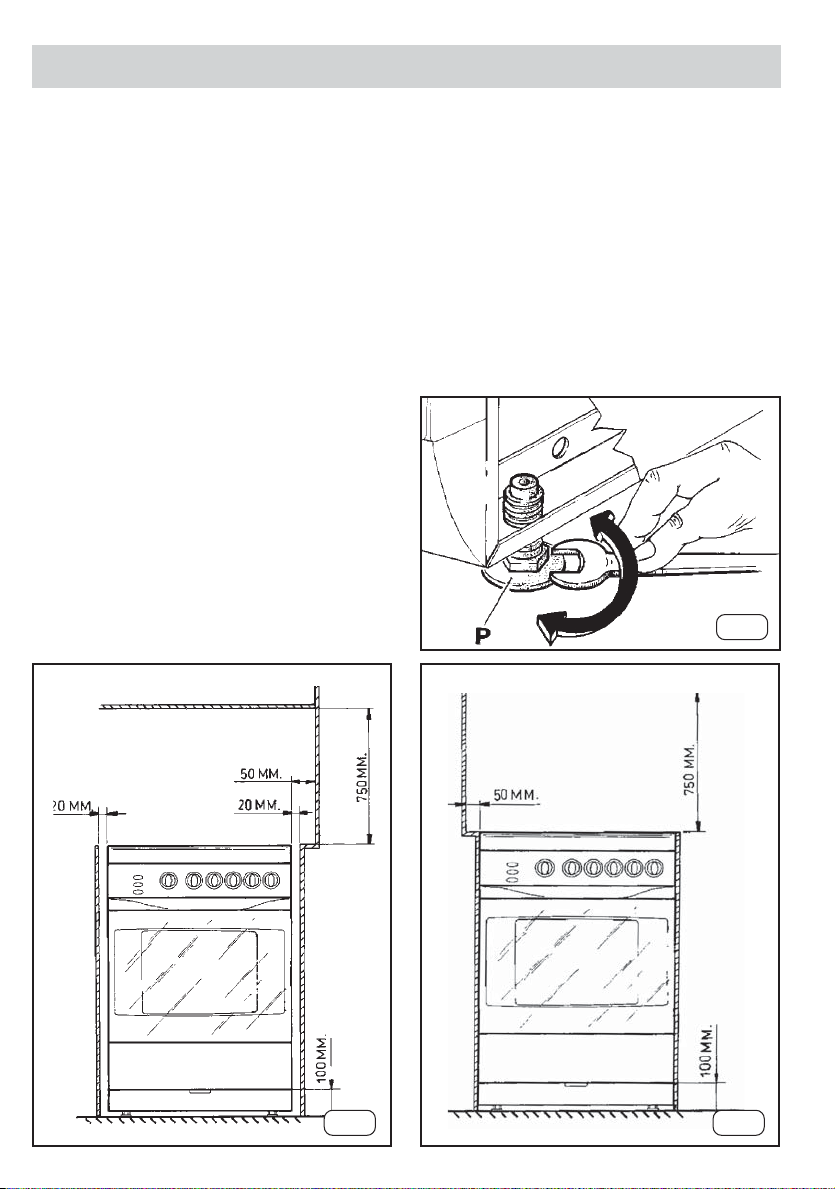
POSITION
The appliance should be positioned in good light and
free from draughts. Any shelf or cupboard of combustible
material should be at least 750mm above the hob top,
a greater clearance is desirable if discoloration is to be
avoided, otherwise the shelf etc. should be protected.
In accordance with the gas standards, the gas
appliances can be installed as “class 1” (free standing)
or “class 2 subclass 1” (recessed) and, as such, must
comply with the clearances specified in figures 1 and 2
respectively.
The rear wall and surfaces adjacent to or surrounding
the appliance must be able to resist a temperature rise
of 65(C. We recommend fitting ceramic tiles to protect
the surrounding surfaces.
NOTE: When installing the appliance adequate space
must be provided to allow the glass lid (where fitted) to
be opened to its fullest extent.
LEVELLING THE COOKER
• It is important that the cooker is placed on a firm
level surface and that the feet, are adjusted to
ensure that the cooker is perfectly level. An
unlevelled cooker can affect the cooking results.
To level the cooker simply adjust the feet (P) (See
diagram below) screwing up or down as required.
By turning these feet you can align the cooker height
with the adjacent work surfaces.
• The cooker is fitted with two spacers placed at the
rear part of the hob top, which ensures a minimum
distance between the appliance and the rear wall.
They must not be removed.
FIG.3
G83
FIG.2FIG.1
6
INSTRUCTIONS FOR THE INSTALLER
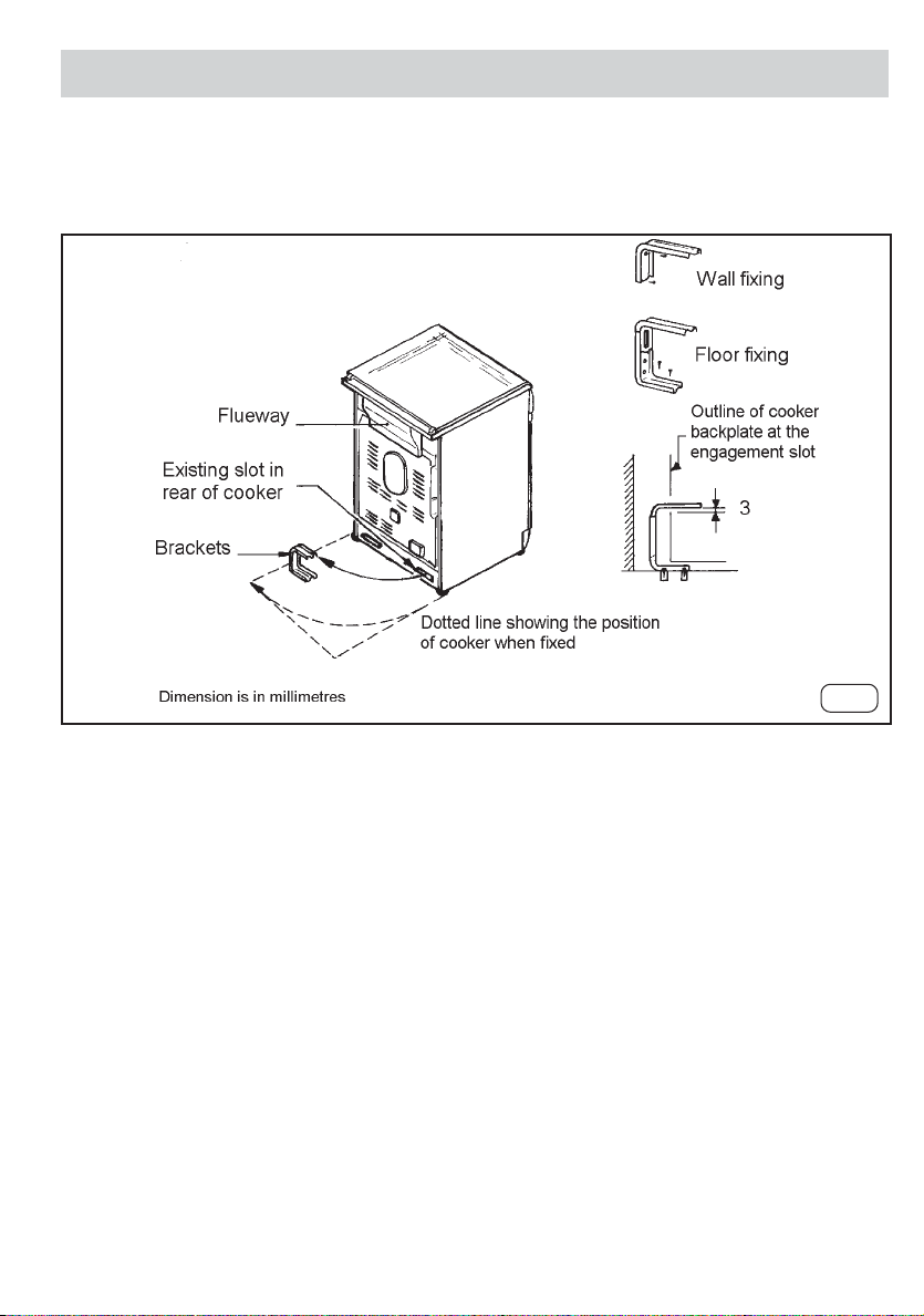
STABILITY BRACKET
We recommend a stability bracket is fitted to the cooker. The type shown in the diagram below can be purchased
from most plumbers merchants and DIY shops.
FIG.4
Note: The power supply cable must be positioned so that no part of the cable can come into contact with any
surface which could reach temperatures in excess of 75°C.
G83
INSTRUCTIONS FOR THE INSTALLER
7
ELECTRICAL CONNECTION
WARNING! THIS APPLIANCE MUST BE EARTHED!
Your cooker should have been checked to ensure that
the voltage corresponds with the supply voltage, this is
stated on the rating plate, which is situated on the rear
of the cooker. The cooker must be connected by a
qualified electrician to a suitable double-pole control unit
with a minimum of 32A and a minimum contact
clearance of 3mm, which should be fitted adjacent to
(but not above) the cooker, in accordance with IEE
regulations. The power supply cable should conform to
BS6004. W e recommend P.V.C. insulated twin and earth
cable with a conductor size of 6mm2 .. The control unit
should be easily accessible in the event of an emergency .
This appliance conforms to EN55014 regarding
suppression of radio and television interference.
Allow sufficient cable length for the cooker to be pulled
out for cleaning, but do not let it hang c loser than 50mm
(2") to the floor. The cable can be looped if necessary,
but make sure that it is not kinked or trapped when the
cooker is in position.
Before you cook for the first time, we recommend that
you switch on each element in turn to burn off any odours
remaining from
manufacture. Simply operate the grill on maximum for
a few minutes, and the oven for approximately 30
minutes. Ensure that the room is well ventilated (eg.
open a window or use an extractor fan) and that persons
who may be sensitive to the odour avoid any fumes. It
is suggested that any pets be removed from the room
until the smell has ceased.
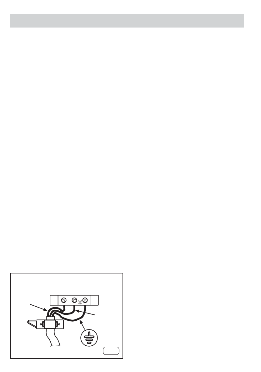
Connection to the mains terminal block as shown below.
It is accessed by removing the cooker back panel.
G83
L
LN
N
FIG.5
8
INSTRUCTIONS FOR THE INSTALLER
GAS CONNECTION
WARNING! This appliance is adjusted for NATURAL GAS
at 20 mbar ONLY.
The hob is suitable for conversion to Liquid Petroleum
Gas (BUTANE (G30) at 28-30 mbar and PROP ANE (G31)
at 37 mbar) by the follo wing procedure using the kit
supplied.
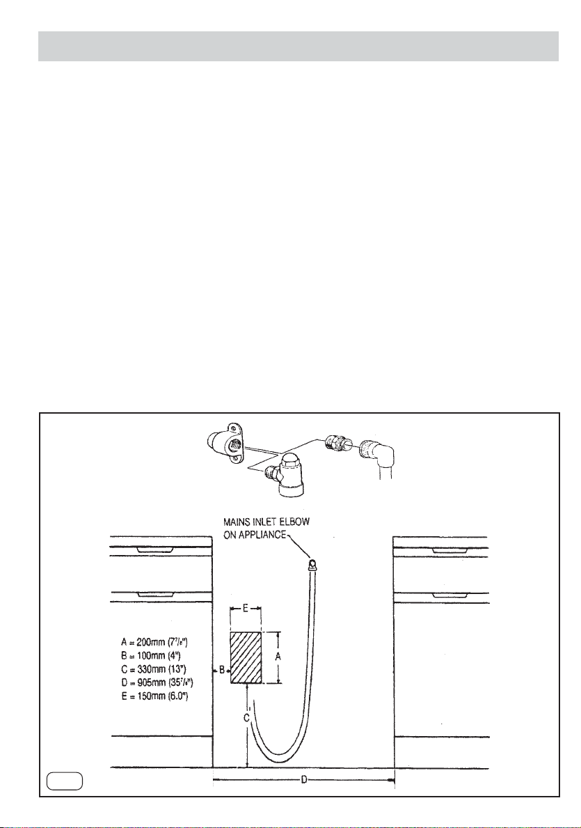
CONNECTING TO GAS SUPPLY
The cooker is designed to match the depth of standard
600mm worktops. An adaptor backplate should,
therefore, be fitted within the shaded area shown to
allow the cooker to be pushed fully to the wall.
Connection to the cooker should be made with an
approved appliance flexible connection to BS 669. A
length of 0.9 to 1.25m is recommended. The length of
hose chosen should be such that when the cooker is in
situ, the hose does not touch the floor.
LPG models should be connected with a hose suitable
for LPG and capable of withstanding a pressure of 50
mbar.
The temperature rise of areas at the rear of the cooker
that are likely to come in contact with the flexible hose
do not exceed 70ºC
FIG.6
G83
INSTRUCTIONS FOR THE INSTALLER
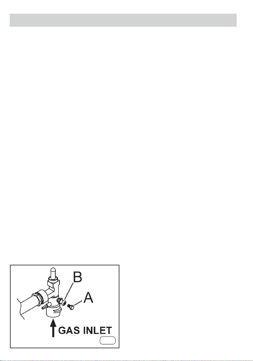
TESTING FOR CORRECT PRESSURE OF GAS
Before attempting to light burners, it is necessary to
ascertain that the correct and desired pressure of gas
is arriving at the appliance.
The test is carried out by removing screw (A) from the
test point (B) and attaching a water gauge tester by
rubber tube to the test point. Turn on the gas and
ascertain the pressure being received (NATURAL GAS,
20 mbar, BUTANE, 28-30 mbar or PROPANE, 37 mbar).
Should the pressure be lower or in excess of the desired
pressure then the installer should consult the gas
supplier . With LP Gas, the installer must ensure that the
correct regulator is fitted and particular attention should
be made when one or more appliances are operating at
the same time so as to obtain correct reading at the
test point on the cooker . Once the correct pressure has
been ascertained, replace screw (A).
After ensuring that the correct gas pressure is being
supplied to the appliance and if the appliance is to be
operated with natural gas, you can now proceed to light
the burners to ascertain that they are burning correctly.
If the appliance is to be converted for use with L.P. gas,
please follow the conversion instructions prior to testing
the hotplate burners.
9
G83
FIG.7
 Loading...