

Belling 152 Installation And User Instruction Manual

Installation & User’s Instructions
Model No. 152
This model is supplied for use with Natural gas,
and is convertible to LPG with the kit provided.
Belling
Cookcenter
Dual Fuel Cooker

Contents
Introduction..................................................................................................................3
Installation Instructions ........................................................................................4-10
For Your Safety Always ............................................................................................11
For Your Safety Never ...............................................................................................12
Know Your Cooker................................................................................................13-14
Know Your Timer...... ..........................................................................................15-19
Hob..................... ..........................................................................................................20
Griddle ........................................................................................................................21
Warming Zone ............................................................................................................22
Oven Temperature Chart ..........................................................................................23
Grilling ........................................................................................................................24
Fan oven cookery notes and charts ..................................................................25-28
Conventional oven cookery notes and charts ................................................29-32
Slow Cook/Warming Oven .......................................................................................33
Care And Cleaning................................................................................................34-35
Is There Something Wrong?. ..............................................................................36-37
Spares And Service ......................................................................................Rear Cover
2

Thank you for purchasing a new Belling Cookcenter. Its stylish and practical
design will enhance your kitchen and make cooking a pleasure. It features a
fan, a conventional oven, a slow cook / warming oven, a separate grill, a seven
burner hob with a warming area and removable griddle plate. There is also a
clock / timer with a minute minder and automatic oven switch on and off.
If you have any problems with installing, operating, or cooking with your
Belling cooker, please check through these instructions thoroughly to make
sure that you have not missed anything. If you still need help then please
contact (including a daytime telephone number if possible):
Consumer Relations Department,
Belling Appliances Ltd.,
Talbot Road,
Mexborough,
South Yorkshire,
S64 8AJ
Belling helpline Tel: 01709 579902.
Please quote the cooker model and serial number with all enquiries. The serial
number can be found on the left hand side of the oven frame.
WARNING! For your own safety, make sure that these instructions on
installation, use and maintenance are followed.
We advise you to keep these instructions in a safe place for future reference.
If you sell or transfer ownership of this product, please pass on these
instructions to the new owner.
After unpacking your cooker, make sure that you remove all the packing from
the oven and grill and any stickers from the oven/grill door and the hob.
Belling provide a range of cleaning materials for your new cooker. Please call
01709 579907 for details.
Grill Compartment smoothglide system Part number Belling 027
Main Fan Oven smoothglide system Part number Belling 028
Kebab Rack for Grill Compartment Part number Belling 029
Getting help
Unpacking
Cleaning
Accessories
3
Your Belling
Cooker
Introduction

4
Installation Instructions
Prior to installation, ensure that the local distribution conditions (nature of the
gas and gas pressure) and the adjustment conditions are compatible. The
adjustment conditions for this appliance are stated on the data badge which is
fitted on the rear panel.
This appliance is not designed to be connected to a combustion products
evacuation device. It must be installed and connected in accordance with
current installation regulations. Particular attention should be given to the
relevant requirements regarding ventilation.
Model number: 152
Category II
2H3+
(GB, IE)
This model is set to burn NATURAL GAS (G20) at 20mbar and can be converted
for use on BUTANE (G30) at 28-30mbar and PROPANE (G31) at 37mbar with
the kit supplied.
GAS SAFETY (INSTALLATION & USE) REGULATIONS
It is the law that all gas appliances are installed by competent persons in
accordance with the current edition of the above regulations. It is in your interest and that of safety to ensure compliance with the law.
In the UK, CORGI registered installers work to safe standards of practice.
The cooker must also be installed in accordance with BS 6172.
Failure to install the cooker correctly could invalidate the warranty liability
claims and could lead to prosecution.
LOCATION
The cooker may be located in a kitchen, kitchen/diner or a bed-sitting room,
but not in a room containing a bath or shower. The cooker must not be
installed in a bed-sitting room of less than 20m3.
When adjusted for use on butane (G30) or propane (G31) these models must
not be installed in a room or internal space below ground level, e.g. in a
basement.
PROVISION FOR VENTILATION
The room containing the cooker should have an air supply in accordance with
BS 5440:Part 2:.
The room must have an opening window or equivalent; some rooms may also
require a permanent vent. If the room has a volume between 5 and 10m3, it
will require an air vent of 50 cm2effective area unless it has a door which
opens directly to outside. If the room has a volume of less than 5m3, it will
require an air vent of 100 cm2effective area. If there are other fuel burning
appliances in the same room, BS 5440: Part 2: should be consulted to determine
air vent requirements.
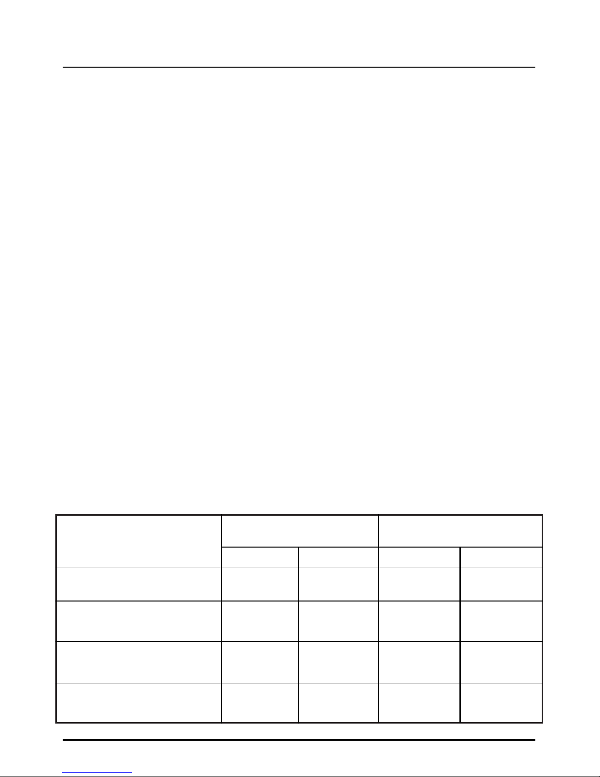
HOTPLATE
Front Left & Rear Centre Right
(Semi Rapide)
NATURAL GAS Models
L.P.G. Models
102
1.9kW
3.1 kW
HOTPLATE
Front Centre Left (Wok)
Installation Instructions
5
TECHNICAL DATA
DIMENSIONS
Height 900 - 915mm
Width 1090mm
Depth 600mm (excluding door handles)
GENERAL
Gas connection Rp 1/2(1/2” BSP female)
Supply pressure Natural Gas Models - G20 at 20mbar
Convertible to Butane (G30) at 28-30mbar
or Propane (G31) at 37mbar
Pressure test point Rear Centre Right hob burner (Semi-Rapide)
Gas rate adjustment None
Aeration adjustment None
Electrical connection 6mm2PVC insulated twin and earth
230 -240V a.c. 50Hz
Total Heat Input (Natural Gas) 14.7kW.
Total Heat Input (LPG Gas) 14.2kW. (1033gms/h - G30) (1015gms/h - G31)
Total Heat Input (Electric) 7.43 - 8.10kW.
Fan Oven Wattage 2.30 - 2.50kW.
Grill 2.44 - 2.66kW.
Conventional Oven 2.20 - 2.40kW.
Slow Cook/Warming Oven 0.20 - 0.22kW.
Warming Zone 0.11 - 0.12kW
HEAT INPUT
HEAT INPUT
BURNER
INJECTOR
INJECTOR
130
3.0 kW
(218gms/h - G30)
(214gms/h - G31)
2.8 kW
(204gms/h - G30)
(200gms/h - G31)
1.0 kW
(73gms/h - G30)
(72gms/h - G31)
1.8 kW
(131gms/h - G30)
(129gms/h - G31)
90
82
65
50
HOTPLATE
Rear Left & Front Centre Right
(Rapide)
HOTPLATE
Front Right & Rear Right
(Auxiliary)
128
1.0 kW
72
2.9 kW

1090
400
6
Space For Fixing
The cooker can be close fitted below hotplate level. This
requires a minimum distance of 1090mm between
cupboard units of hotplate height.
The wall behind the cooker between the hotplate and
450mm above, and across the width of the cooker, must be
an incombustible material such as ceramic wall tiles.
Follow the diagrams below for guidance on fitting.Take note
of all dimensions.
If your appliance is to be fitted close to a corner ensure that
there is a clearance of 135mm minimum. This will enable
you to fully open the door and allow removal of oven
shelves.
1090
1090
2050 min
Gap can be in filled
below hotplate
level
65
1090
1090
794
25 min
400
min
2050 min
Cupboards
or wall
Appliance
Cupboar
d
135 min
Fig. 1
INSTALLATION WITH WALL CUPBOARDS
IN LINE WITH SIDES OF APPLIANCE
Fig. 3
INSTALLATION ALONGSIDE TALL CUPBOARDS OR SIDEWALL
Fig. 4
INSTALLATION CLOSE TO A CORNER
Fig. 2
INSTALLATION USING BRIDGING
CUPBOARDS
1200
Installation Instructions
Unpack the components from inside the grill and oven: Check
that the following parts are present.
Grill pan and grid
Pan supports (3)
Main oven shelves (4)
Meat pan
Literature
Griddle
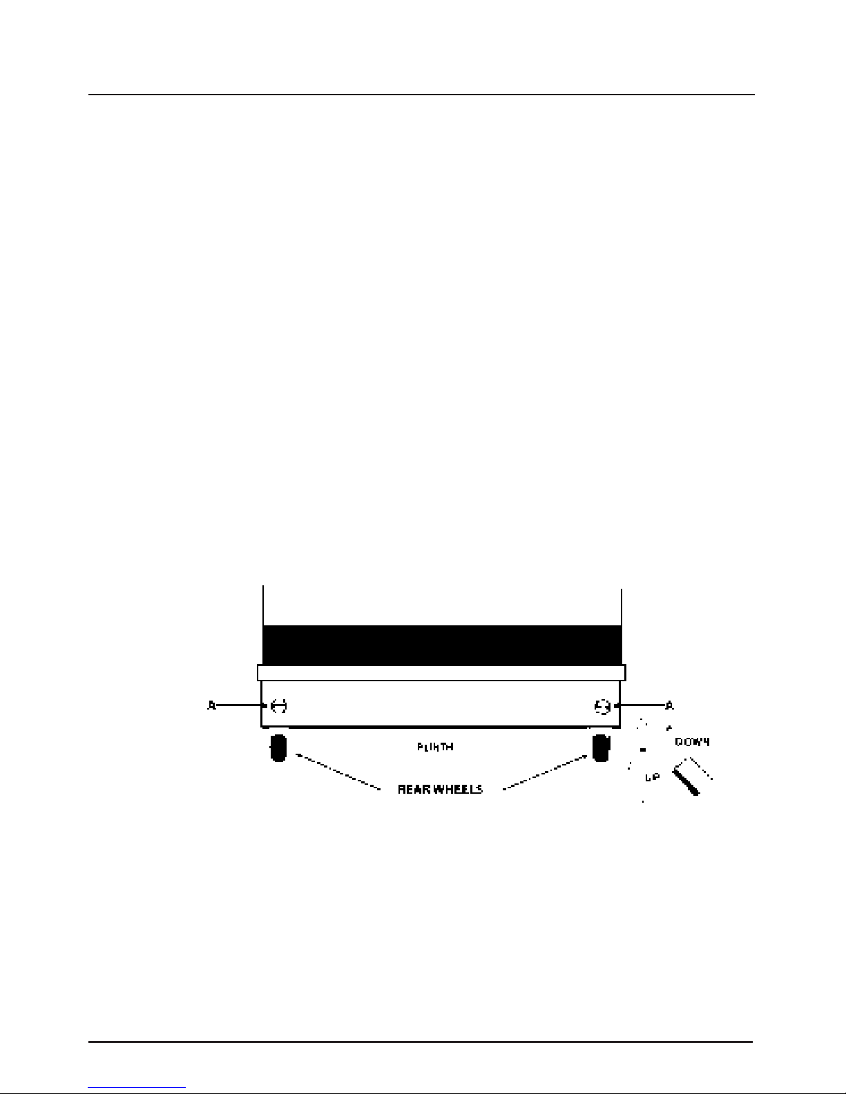
Two rear wheels and two front feet are fitted which can be adjusted up or down to set the height (900mm - 915mm) and level the
cooker.
1. The rear wheels can be raised or lowered from the BACK of the
cooker by adjusting the levelling screws ‘A’ in the plinth.
2. The front feet can be simply screwed in or out to lower or raise
the front of the cooker.
Some soft floor coverings may get damaged if the cooker is not
moved carefully.
7
UNPACKING
THE COOKER
LEVELLING
CAUTION:
VIEWED FROM THE REAR
Installation Instructions
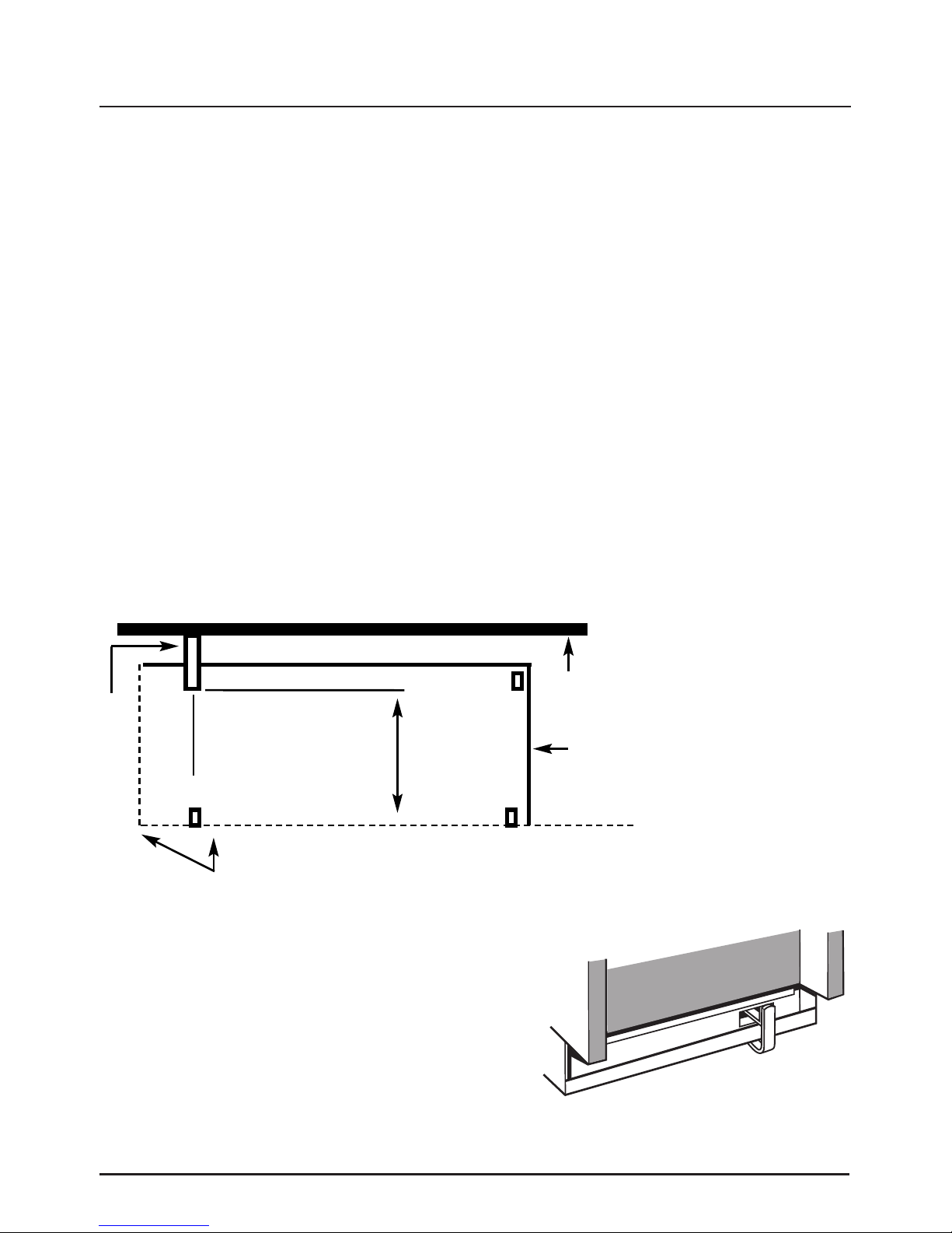
The back of the cooker has a slot for engagement of a
stability bracket, which can be obtained, as an extra, from the
cooker supplier. The leaflet included with the bracket should
be read in conjunction with the following instructions:
Push cooker to its intended position.
Draw pencil lines on the floor in line with the front and
left side of the plinth.
Remove the cooker.
Position stability bracket in accordance with diagram
below.
Measure height from floor level to the bottom of the
slot in the back of the cooker.
Add 3mm to the dimension and assemble the stability
bracket to that height. (i.e. from floor level to the
underside of the top member).
Stability
Bracket
8
PENCIL LINE
PLINTH
BRACKET
WALL
92
mm
410mm
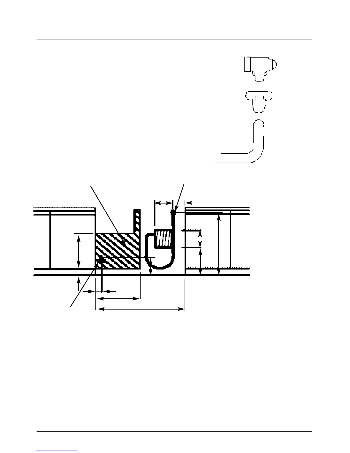
Connecting to the Gas Supply
9
This area to be
clear of pipework
and obstructions
450
250
770
80
470
1090
570
160
60
75
Mains Inlet on Appliance
Electrical
Connection
Connection to the cooker should be made with an approved appliance flexible connection
to BS 669. A length of 0.9 to 1.25m is recommended. The length of hose chosen should
be such that when the cooker is in situ, the hose does not touch the floor.
LPG models should be connected with a hose suitable for LPG and capable of withstanding
pressure of 50 mbar.
The temperature rise of areas at the rear of the cooker that are likely to come in contact
with the flexible hose do not exceed 70˚C.
After installation, check for soundness.
The supply pressure is tested at the hob burner.
With reference to the user’s instructions:
1. Check that the hotplate burners ignite correctly and burn with a steady flame.
2. Check for a steady flame at the low (small flame symbol) setting.
3. Instruct the user on the operation of the cooker.
The cooker is designed to match the depth of
standard 600mm worktops. An adaptor backplate
should, therefore, be fitted within the 160 x
250mm shaded area shown, pointing towards the
left to allow the cooker to be pushed fully to the
wall. If a forward facing backplate is used, it must
be chased into the wall.
250

Connecting to Electrical Supply
10
Connecting The
Cooker
Before Cooking
For your own safety, we recommend that your cooker is installed by
a competent person. The cooker should be installed in accordance
with the latest edition of the IEE regulations.
WARNING! THIS COOKER MUST BE EARTHED.
The cooker must be connected to the correct electrical supply as
stated on the rating plate, through a suitable cooker control unit
incorporating a double pole switch having a contact separation of
at least 3mm in all poles, adjacent to (but not above) the cooker.
We recommend the cooker circuit be rated to 45 amps with a
minimum of 32 amps.
We recommend that 6mm
2
PVC insulated twin and earth cable is
used to connect the cooker to the cooker control unit. The
minimum size of cable that can be used is 6mm
2
twin and earth,
the maximum size is 10mm
2
twin and earth.
The power supply cable should conform to BS6004.
IMPORTANT. For access to the mains terminal block, for supply
cable connection, it is necessary to remove the mains terminal
cover, located at the lower right hand side of the rear panel. No
part of the appliance will operate unless the main control unit is
switched ON.
Allow sufficient cable length for the cooker to be pulled out for
cleaning, but do not let it hang closer than 25mm (1") to the floor.
The cable can be looped if necessary, but make sure that it is not
kinked or trapped when the cooker is in position.
This appliance conforms to BS EN55014 regarding suppression of
radio and television interference.
Before you cook for the first time, we recommend that you switch
on each element in turn to burn off any odours remaining from
manufacture.
Run oven elements for 1/2 hr on maximum.

For Your Safety
11
Please read the precautions below before using your
cooker.
● Always make sure you understand the controls before using
the cooker.
● Always check that all controls on the cooker are turned off
after use.
● Always stand back when opening an oven door to allow heat
to disperse.
● Always use dry, good quality oven gloves when removing items
from the ovens.
● Always take care when removing items from the top oven/grill
when the main oven is on, as the contents may be hot.
● Always keep the oven and grill doors closed when the cooker is
not
in use.
● Always place pans centrally over the hotplate burners and
position them so that the handles cannot accidentally be
caught or knocked or become heated by other burners.
● Always keep the cooker clean, as a build up of grease or fat
from cooking can cause a fire.
● Always allow the cooker to cool before cleaning.
● Always follow the basic principles of food handling and
hygiene to prevent the possibility of bacterial growth.
● Always keep ventilation slots clear of obstructions.
● Always turn off the electricity supply before cleaning or
replacing the oven lamp.
● Always refer servicing to CORGI registered appliance service
engineers.
● Always ensure that the Griddle is fitted correctly to the pan
supports and that the fingers are located correctly within the
slots in the Griddle feet.
Always..

● Never leave children unsupervised where the cooker is installed
as all surfaces will get hot during and after use.
● Never allow anyone to sit or stand on any part of the appliance.
● Never store items that children may attempt to reach above the
appliance.
● Never fill chip pans more than 1/3 full with oil or fat, or use a
lid. DO NOT LEAVE UNATTENDED WHILE COOKING
● Never use proprietary spillage collectors on the hotplate, eg. foil
spillage bowls.
● Never heat up unopened food containers as pressure can build
up causing the container to burst.
● Never
store chemicals / food stuffs, pressurised containers in or
on the appliance,
or in cabinets immediately above or next to
the appliance.
● Never place flammable or plastic items on or near the hotplate.
● Never use the cooker as a room heater.
● Never dry clothes or place other items over or near to the hot
plate or oven/grill doors eg. tea towels & oven gloves.
● Never wear garments with long flowing sleeves whilst cooking.
● Never leave items that could catch fire (tea towels etc.) near to
the burners or over the flue outlet.
● Never leave burners lit when not in use.
● Never use plastic items in or on the appliance.
For Your Safety
NEVER..
12
 Loading...