

Page 1
Product Data
Page 2

THIS ELECTRONIC DOCUMENT MAY HAVE BEEN SUPERCEDED.
THE MOST CURRENT DOCUMENT INFORMATION IS AVAILABLE
THIS IS AN UNCONTROLLED DOCUMENT.
FROM YOUR BELL HELICOPTER TEXTRON REPRESENTATIVE.
DISCLAIMER
THIS INFORMATION CONTAINED HEREIN WAS PREPARED AND INTENDED, ONLY,
AS A MARKETING AID. IT CANNOT BE USED AS A SUBSTITUTE FOR THE
ROTORCRAFT FLIGHT MANUAL, MAINTENANCE MANUAL, ILLUSTRATED PARTS
BREAKDOWN OR OTHER PUBLICATIONS APPROVED BY AIR REGULATORY
AUTHORITIES FOR THE OPERATION, AND/OR MAINTENANCE OF ANY BELL
AIRCRAFT.
PUBLISHERS NOTICE
The data presented herein is general in nature and is intended for the use of BHTI
Sales Personnel and International Sales Representatives as an aid in describing
the features and benefits of Bell Helicopters to prospective customers.
This data includes proprietary material of BHTI. Disclosure, reproduction, or use of
any of the material herein by persons other than
BHTI employees, and BHTI Independent
Representatives [International Dealers] is forbidden without written permission from
BHTI.
The PHOTOGRAPHS and DRAWINGS appearing herein are for illustration only, and
may differ from the actual aircraft, as the BHTI continuing product improvement process
causes some components, specifications, and procedures to be changed or replaced.
THE WEIGHTS, DIMENSIONS, AND PERFORMANCE DATA SHOWN MAY NOT BE
CURRENT. For the
most current tabular data, and performance and fuel flow charts
refer to the current year’s Technical Information Booklets.
©Copyright, Bell Helicopter Textron, Inc., 2003 ®™, Bell Helicopter, Bell Helicopter Textron Inc., Bell
206B3, 206L-4, 407, 427, 430, 412, 609, JetRanger and
LongRanger are registered trademarks of Bell
Helicopter Textron Inc.
PRODUCT DATA JANUARY 2003
2
Page 3

THIS ELECTRONIC DOCUMENT MAY HAVE BEEN SUPERCEDED.
THE MOST CURRENT DOCUMENT INFORMATION IS AVAILABLE
THIS IS AN UNCONTROLLED DOCUMENT.
FROM YOUR BELL HELICOPTER TEXTRON REPRESENTATIVE.
BELL 430
PRODUCT DATA
CONTENTS
SECTION ONE GENERAL DESCRIPTION OF
THE STANDARD CONFIGURATION
SECTION TWO OPTIONAL EQUIPMENT
FACTOR Y INSTALLED
BHTC & VENDOR STC KITS
SECTION THREE DIMENSIONS,
DESIGN SPECIFICATIONS
AND WEIGHTS
ALPHABETICAL INDEX
PRODUCT DATA JANUARY 2003
3
Page 4

THIS ELECTRONIC DOCUMENT MAY HAVE BEEN SUPERCEDED.
THE MOST CURRENT DOCUMENT INFORMATION IS AVAILABLE
THIS IS AN UNCONTROLLED DOCUMENT.
FROM YOUR BELL HELICOPTER TEXTRON REPRESENTATIVE.
Atmosphere
Rate of Climb
Speed and Distance
INTERNATIONALLY APPROVED ABBREVIATIONS
GLOSSARY
C
Degrees Celsius (° is not required if meaning is clear.)
ISA
ISA+20 C
ISA+30 C
SL
R/C
ft/min
m/s
km
km/h
International standard atmosphere. (Standard temperature is defined
as 15°C at sea level, with a lapse rate of -1 °C for each 150 meters (500
feet) increase in pressure altitude.)
International standard temperatures increased at each altitude by a
constant 20 C or 30 C.
Sea level.
Rate of climb.
Feet per minute.
Meters per second. (One meter per second is 3.28 ft/s )
h
Hour/hours.
Kilometer/kilometers.
Kilometers per hour. (One kilometer per hour equals 0.54
knots or 0.62 statute miles per hour.)
Knots. (Nautical miles per hour.)
Weights
Performance
Definitions
mph
nm
sm
kg
IGE
OGE
max
Maximum Endurance
Speed
Long Range Cruise
Speed
M
Meter/meters. (One meter equals 3.28 feet.)
Statute miles per hour. (One mile per hour equals 0.87
knots. )
Nautical miles.
Statute miles.
Kilogram/kilograms.
lb
Pound/pounds. (One pound equals 0.45 kilograms.)
In ground effect. (Hovering near the ground creates a
cushion of air that increases the weight carrying capability
of the helicopter (the ground effect). This effect generally
is present up to one rotor diameter above the ground.)
Out of ground effect. (Since the ground effect extends up to
one rotor diameter out of ground effect refers to flight that is
higher than this height above the ground.)
Maximum.
The speed at which power required to fly is a minimum.
The higher of the two speeds at which 99% of maximum
range occurs. Cruising at this speed is a tradeoff of one
percent in maximum range for 20 to 30 kilometers per hour
(10 to 15 knots), higher speed.
Pressure Altitude
Service Ceiling
PRODUCT DATA JANUARY 2003
The altitude indicated on an altimeter or barometer when
the sea level standard pressure reading is the reference
(1013 millibars (29.92 inches) of mercury).
The altitude at which the maximum rate of climb capability
is 0.5 meters per second, 100 feet per minute.
4
Page 5

THIS ELECTRONIC DOCUMENT MAY HAVE BEEN SUPERCEDED.
THE MOST CURRENT DOCUMENT INFORMATION IS AVAILABLE
THIS IS AN UNCONTROLLED DOCUMENT.
FROM YOUR BELL HELICOPTER TEXTRON REPRESENTATIVE.
SECTION ONE
GENERAL DESCRIPTION OF
THE STANDARD CONFIGURATION
PRODUCT DATA JANUARY 2003
5
Page 6

THIS ELECTRONIC DOCUMENT MAY HAVE BEEN SUPERCEDED.
THE MOST CURRENT DOCUMENT INFORMATION IS AVAILABLE
THIS IS AN UNCONTROLLED DOCUMENT.
FROM YOUR BELL HELICOPTER TEXTRON REPRESENTATIVE.
PRODUCT DATA JANUARY 2003
6
Page 7
THIS ELECTRONIC DOCUMENT MAY HAVE BEEN SUPERCEDED.
THE MOST CURRENT DOCUMENT INFORMATION IS AVAILABLE
THIS IS AN UNCONTROLLED DOCUMENT.
FROM YOUR BELL HELICOPTER TEXTRON REPRESENTATIVE.
SYSTEMS OVERVIEW
Introduction
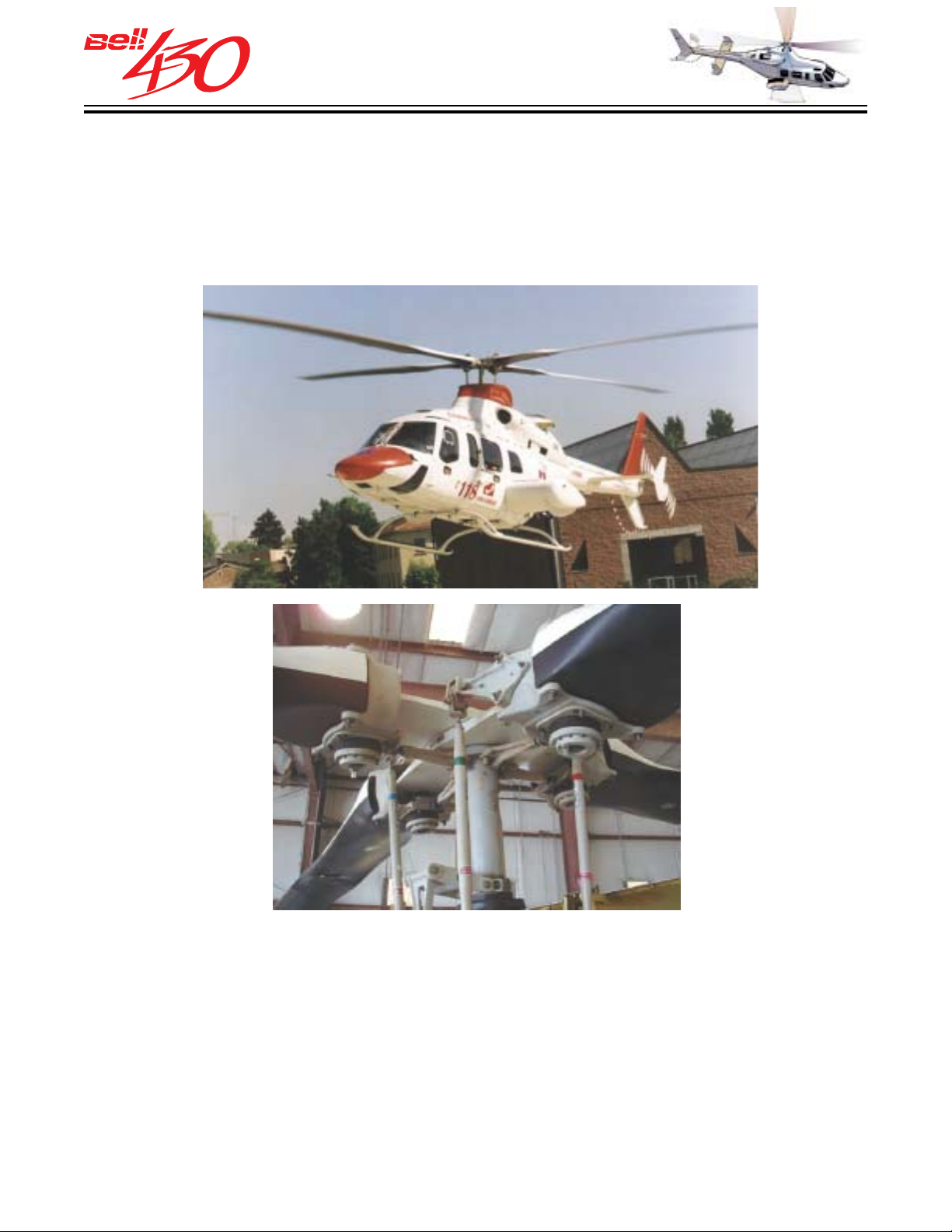
The Bell 430, a 9 to 11 place twin turbine powered helicopter, is the latest version of
Bells' well proven INTERMEDIATE TWIN helicopter series whose heritage reaches
back almost 20 years. This latest model in the series blends the attractive lines of the
222/230 family with Bells' advanced Model 680 Rotor Design.
ADVANCED
FOUR-BLADED
MAIN ROTOR
The Bell 430 FOUR-BLADED bearingless rotor system features primary structural
elements constructed of composite materials to avoid corrosion and to provide benign,
easily detectable failure modes, along with "on-condition" (no retirement life) operation.
Main rotor blade pitch change as well as flapping and lead/lag motions occur through
flexing and bending the two composite yokes (with fluid filled dampers and shear
restraints), rather than by means of the customary hinges and lubricated bearings.
The four blades of the main rotor are of all composite construction with a replaceable
metal leading edge abrasion strip. They are designed for on-condition replacement
and are fully interchangeable. A simplified pylon support system attaches the rotor
and transmission systems to the fuselage.
PRODUCT DATA JANUARY 2003
7
Page 8
THIS ELECTRONIC DOCUMENT MAY HAVE BEEN SUPERCEDED.
THE MOST CURRENT DOCUMENT INFORMATION IS AVAILABLE
THIS IS AN UNCONTROLLED DOCUMENT.
FROM YOUR BELL HELICOPTER TEXTRON REPRESENTATIVE.
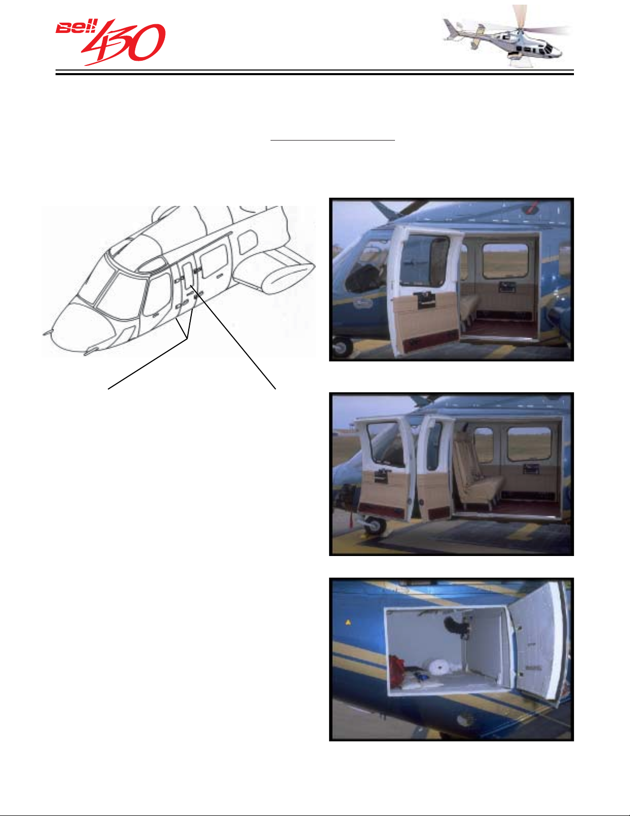
STRETCHED FUSELA GE WITH OPTIONAL PANEL DOOR
The passenger cabin is longer than that of the Bell 222/230 to give each of the three
main cabin seat rows more pitch, making the accommodations more comfortable and
the ride more pleasant. An optional
ease of access for cargo or litters. Located between the left crew and passenger doors
it is attached by hinges to the fuselage and the passenger door in a manner similar to
the Litter Door of the Bell LongRanger & 407 series.
hinged panel door kit is available to provide greater
CABIN STRETCH WITH OPTIONAL LITTER DOOR
COMFOR T F EATURES
The spacious cabin is easily entered through the wide (nearly 180°) opening passenger doors, and provides comfortable
seating for seven (standard seats) , with
ample room for baggage. The 1.05 cubic
meter (37.2 cubic feet) aft baggage
compartment is accessible through it's own
door, or through the rear cabin partition.
Cabin furnishings include the high backed
non-folding seats with three-point lap /
shoulder restraints, and the standard
deluxe interior trim, headliner /
soundproofing, hard thermoplastic wall
covering, and vinyl floor covering. The SIX
large cabin windows afford each
passenger a panoramic view. The cabin
ventilation system directs fresh outside
air to each seat from individual overhead
outlets. In flight, the cabin's occupants
receive a smooth vibration-free ride,
®
courtesy of the LIVE
suspension.
MAIN PASSENGER DOOR
OPTIONAL LITTER DOOR
BAGGAGE DOOR
PRODUCT DATA JANUARY 2003
8
Page 9
SAFETY FEA TURES
THIS ELECTRONIC DOCUMENT MAY HAVE BEEN SUPERCEDED.
THE MOST CURRENT DOCUMENT INFORMATION IS AVAILABLE
THIS IS AN UNCONTROLLED DOCUMENT.
FROM YOUR BELL HELICOPTER TEXTRON REPRESENTATIVE.
The primary design parameters of the Bell
430 emphasize safety in every aspect of
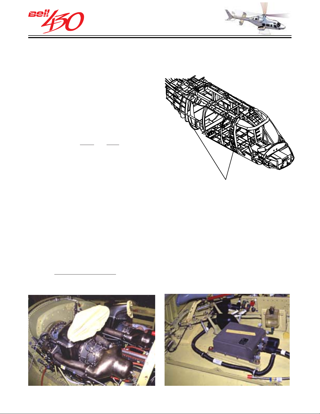
OCCUPANT PROTECTION BY REDUNDANT
FUSELAGE LOAD PATHS
the aircraft. All critical flight systems are
either duplicated or isolated / separated
to meet / exceed the specifications of FAR
Part 29 Category A. Redundant load paths
are incorporated throughout all safety-of-
flight components, such as the main rotor
blades, transmission attachment, and flight
control linkage. Fuselage integrity is
ensured through two integral roll-over
bulkheads at the
front and rear of the cabin.
The fuel supply is contained in rupture-
resistant fabric and rubber cells which have
been drop-tested when 75% full from 15
meters (50 feet) without spillage, and are
interconnected with break-away self-
sealing fittings.
ROLLOVER BULKHEADS
ROLLS-ROYCE 250-C40B ENGINES WITH FADEC
The engines selected for the Bell 430 are the Rolls-Royce 250-C40B. These are a
growth version of the well - proven 250-C30 engine series from Rolls-Royce which
provide reliable power under the extremes of climatic conditions. The Rolls-Royce 250
engine series has accumulated over 100 million hours of flight time, with deliveries
totaling over 30,000 engines. Controlling each engine is a Full Authority Digital
Electronic Control (FADEC). The FADEC provides automatic starting, is able to
maintain rotor speed and engine matching within closer tolerances, and to offer a 30-
second
single engine rating to enhance Category A operations. Additionally, as in all
Bell Helicopters, MANUAL power management of each engine is immediately available
to the pilot through the collective-mounted twist grip throttles.
ROLLS-ROYCE 250-C40B ENGINES FADEC ELECTRONIC CONTROL UNIT
PRODUCT DATA JANUARY 2003
9
Page 10
THIS ELECTRONIC DOCUMENT MAY HAVE BEEN SUPERCEDED.
THE MOST CURRENT DOCUMENT INFORMATION IS AVAILABLE
THIS IS AN UNCONTROLLED DOCUMENT.
FROM YOUR BELL HELICOPTER TEXTRON REPRESENTATIVE.
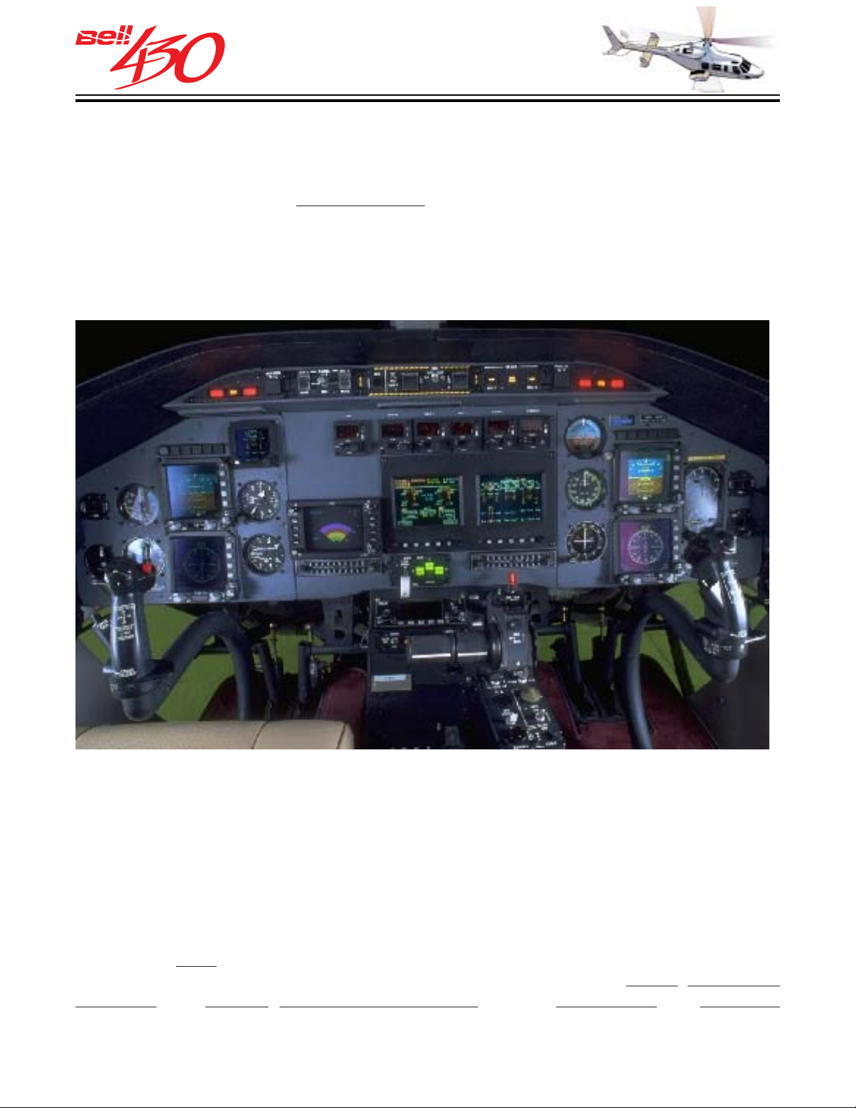
INTEGRA TED INSTRUMENT DISPLAY SYSTEM (IIDS)
Another new feature of the Bell 430 is the Integrated Instrument Display System (IIDS) which reduces the size of the instrument panel and gives the flight crew more forward field of view. The
control, essential parameters of critical helicopter systems. The IIDS also controls the
Chip Detector/Fuzz Burner Functions for both engines (2 each) and the transmission
/ tail rotor (6/1). Additionally, the IIDS has new maintenance and power assurance
functions. As a bonus, the IIDS is a valuable tool which also helps to increase the
helicopter's reliability and maintainability.
Dual Displays help the flight crew to track, as well as to
INTEGRATED INSTRUMENT DISPLAY SYSTEM (IIDS) - SHOWN WITH OPTIONAL EQUIPMENT
MAINTAINABILITY FEATURES
The Bell 430 is engineered for reliability and ease of maintenance. Built in steps and
work platforms, along with plentiful access panels, doors, and inspection windows
provide for quick and thorough preflight checks and servicing. Primary components
and systems are designed for routine servicing while remaining installed on the aircraft.
Major service intervals are among the longest in the rotorcraft industry due to Bell's
traditionally
have not, and will not change ; Bell Helicopter's commitment to
operation, and reliable, responsive helicopters that are supportable and economic
through their lifetimes.
PRODUCT DATA JANUARY 2003
long Time Between Overhaul / Retirement Life components. Some things
safety, low cost of
10
Page 11
THIS ELECTRONIC DOCUMENT MAY HAVE BEEN SUPERCEDED.
THE MOST CURRENT DOCUMENT INFORMATION IS AVAILABLE
THIS IS AN UNCONTROLLED DOCUMENT.
FROM YOUR BELL HELICOPTER TEXTRON REPRESENTATIVE.
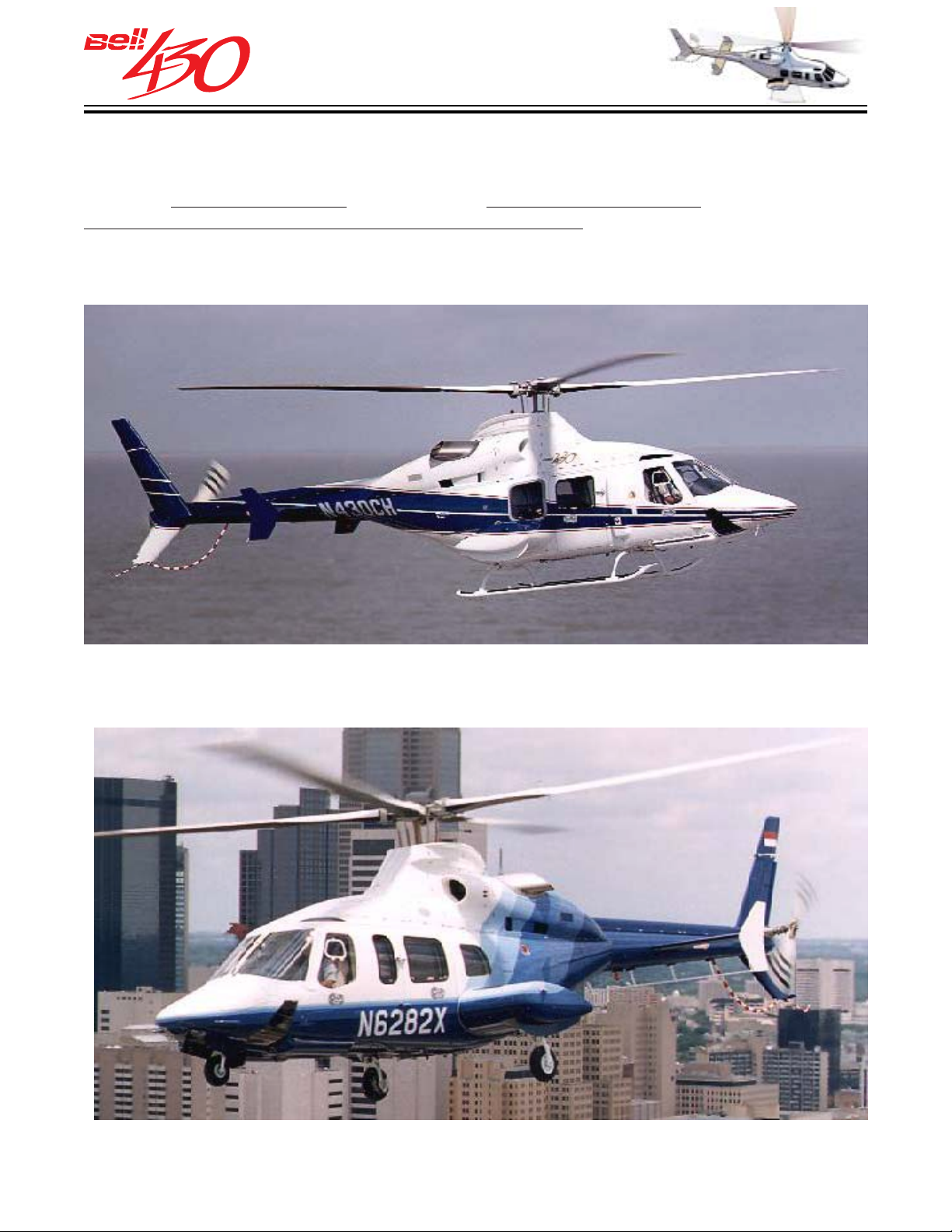
LANDING GEAR CHOICE
The basic airframe of the Bell 430 is provided with complete provisions for delivery in
either of
RETRACTABLE TRICYCLE WHEEL LANDING GEAR.
two configurations;the standard SKID LANDING GEAR , or the optional
PRODUCT DATA JANUARY 2003
11
Page 12
THIS ELECTRONIC DOCUMENT MAY HAVE BEEN SUPERCEDED.
THE MOST CURRENT DOCUMENT INFORMATION IS AVAILABLE
THIS IS AN UNCONTROLLED DOCUMENT.
FROM YOUR BELL HELICOPTER TEXTRON REPRESENTATIVE.
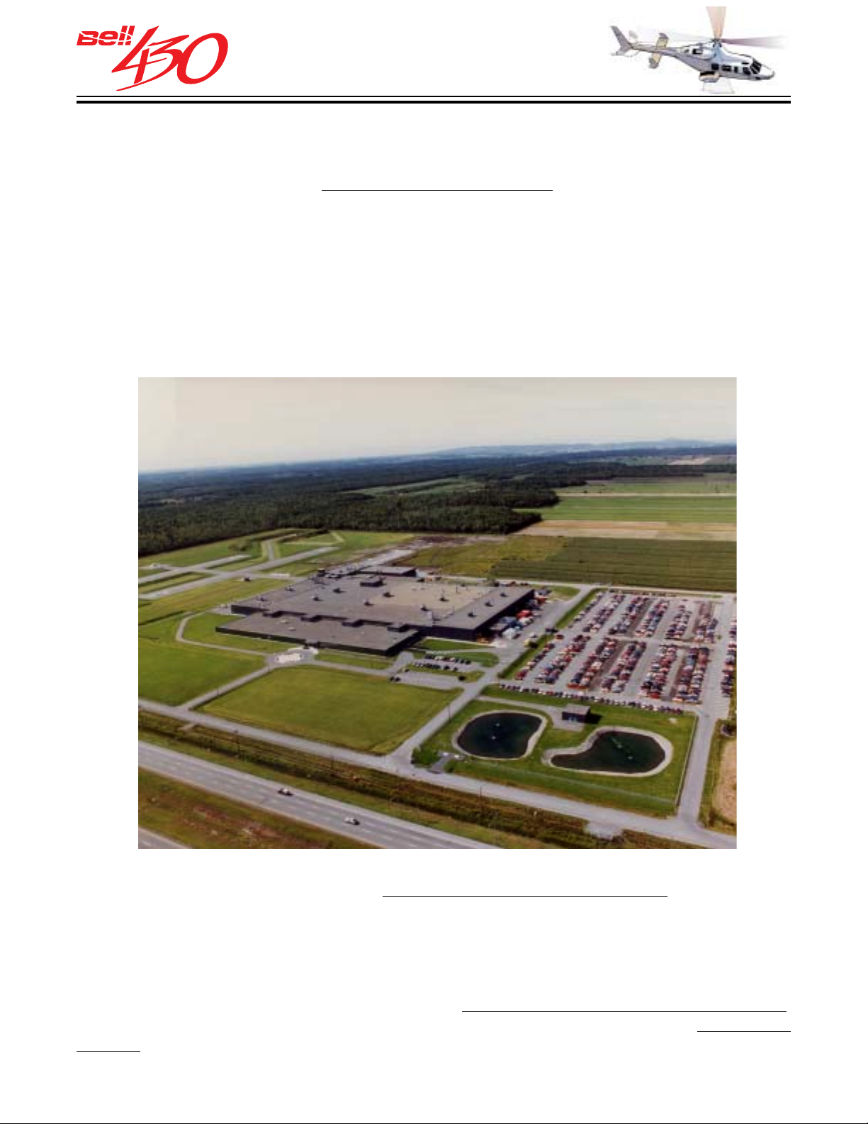
BELL HELICOPTER TEXTRON CANADA, LTD.
The Bell 430 is assembled at Bell Helicopter Textron Canada, Ltd. The manufacturing facilities are situated in Mirabel, Quebec, 19 miles (30 kilometers) North of Montreal.
The plant is a short drive from
Dorval International Airport. The 152-acre site in Mirabel
includes a 529,000 square foot facility that houses manufacturing, fabricating, processing,
assembly, engineering design, research and development, product support engineering,
marketing and administration.
MANUFACTURING AUTHORITY
The Bell 430 received its Canadian Type Approval Certificate [H-88] on February 23,
1996. The Bell 430 was also certificated by the FAA in accordance with provisions of 14
CFR Section 21.29 on April 11, 1996. Initial deliveries of the new Bell 430 began in
February 1996.
BASIS OF CER TIFICATION
The Bell 430 is certified under FAR
the Bell 430 is approved under Canadian Airworthiness Manual Chapters 529, Sections
529.1301.1, 529.1557(c), 529.1518 (e), and 529.1093 (b) (1) (ii).
Part 29, Category B requirements . Additionally,
INTERNATIONAL CERTIFICATION
A new Bell 430 is delivered with a Canadian Certificate of Airworthiness for Export,
which may be readily exchanged for a Certificate of Airworthiness in the
country.
PRODUCT DATA JANUARY 2003
12
destination
Page 13
THIS ELECTRONIC DOCUMENT MAY HAVE BEEN SUPERCEDED.
THE MOST CURRENT DOCUMENT INFORMATION IS AVAILABLE
THIS IS AN UNCONTROLLED DOCUMENT.
FROM YOUR BELL HELICOPTER TEXTRON REPRESENTATIVE.
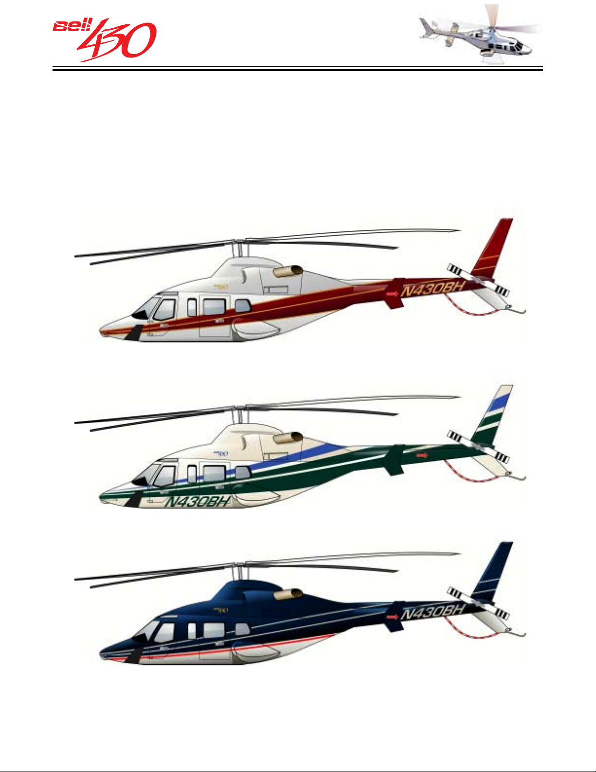
EXTERIOR PAINT SCHEMES
The overall eye appeal of the Bell 430 is aided by the sparkling Polyurethane paint.
Not only is it durable and easy to keep clean, but it maintains and, in fact, exemplifies
the high standard of Bell quality and dependability. The standard Bell 430 comes in
THREE basic color scheme designs illustrated below, each in THREE colors. The
colors are selected from the many shown in the IMRON paint chip chart available
from the Bell representative.
A
B
C
Special company colors, paint design, logos, etc., can be negotiated.
PRODUCT DATA JANUARY 2003
13
Page 14
THIS ELECTRONIC DOCUMENT MAY HAVE BEEN SUPERCEDED.
THE MOST CURRENT DOCUMENT INFORMATION IS AVAILABLE
THIS IS AN UNCONTROLLED DOCUMENT.
FROM YOUR BELL HELICOPTER TEXTRON REPRESENTATIVE.
GENERAL DESCRIPTION
OF THE STANDARD CONFIGURATION
SERIAL NO. 49001 AND SUBSEQUENT
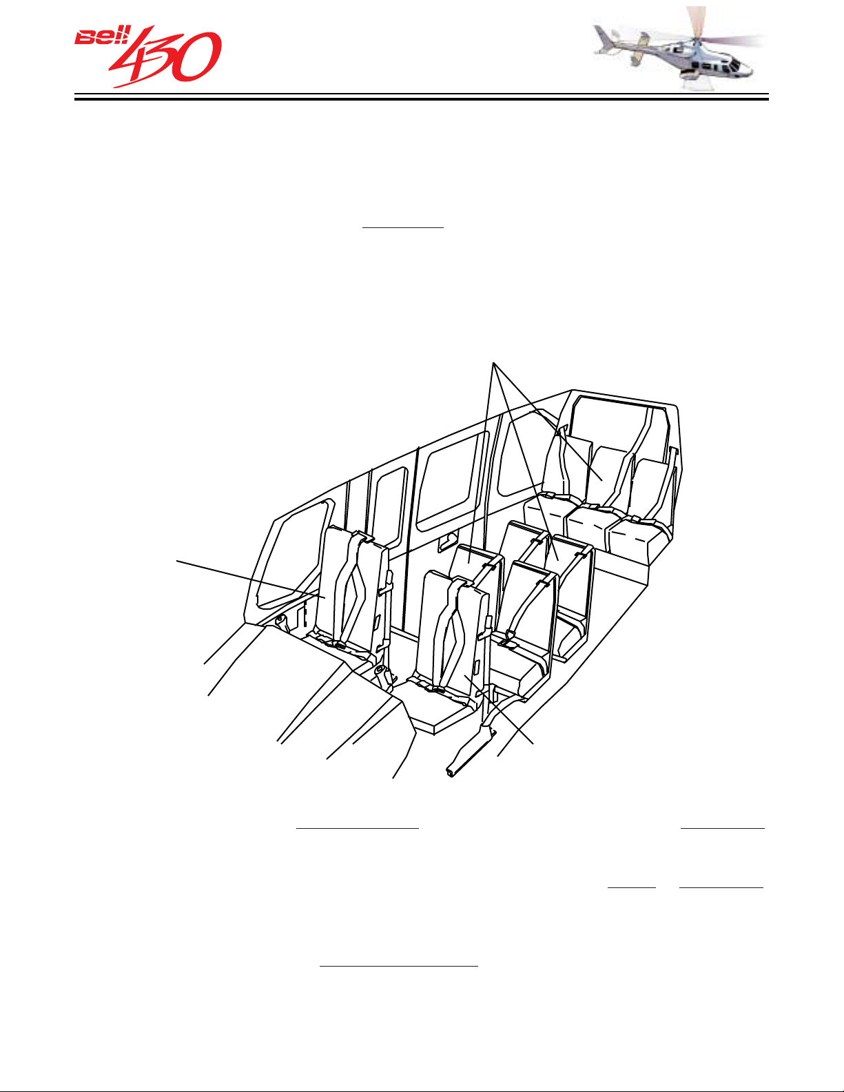
The Bell 430 is the newest of the Bell intermediate twin engine helicopters and is designed
to carry nine to ten adults comfortably, including the pilot. The Bell 430 is approved
for single pilot operation (standard
under day or night VFR non-icing conditions as a Transport Category Rotorcraft (FAR
Part 29, Category B). The standard Bell 430 incorporates all of the redundant systems
necessary for Category A certification.
nine place seating) and is certified for land operation
SEVEN STANDARD CABIN
PASSENGER SEATS IN
THREE ROWS [ 2 X 2 X 3 ]
PILOT'S
SEAT
FORWARD
PASSENGER
OR COPILOT SEAT
The pilot must occupy the
right front seat. A passenger seat is provided on the left,
which may also carry a copilot with the addition of the optional dual flight control kit
[provisions for this kit are standard]. Seven additional passengers can be accommodated
in the spacious main cabin. Passengers can enter the cabin from
either or both sides.
Two rows of two seats, centrally located, face forward. The remaining three seats are
in a row, facing forward, on a bench at the rear of the compartment. This is the STANDARD
nine place interior. Headliners, soundproofing, carpet and upholstered seats add to
the comfort. Conversion from
passenger to cargo configuration is easily accomplished
by removing the cabin seats.
PRODUCT DATA JANUARY 2003
14
Page 15
THIS ELECTRONIC DOCUMENT MAY HAVE BEEN SUPERCEDED.
THE MOST CURRENT DOCUMENT INFORMATION IS AVAILABLE
THIS IS AN UNCONTROLLED DOCUMENT.
FROM YOUR BELL HELICOPTER TEXTRON REPRESENTATIVE.
430 SEATING
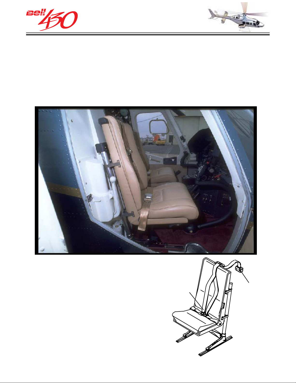
PILOT AND FORW ARD PASSENGER SEATING
Two individual ergonomically designed energy-attenuating bucket seats with adjustable
lumbar support, each equipped with seat belt, double strap [four point] shoulder harness
and inertia reel, with "Quick Release" mechanism, are located in the cockpit. The color
and upholstery material for the seats, and interior trim of the cockpit match that which
is selected for the cabin.
OCCUPANT RESTRAINT
Each crew and passenger seat is equipped
with a restraint assembly that consists of
an inertia reel, a shoulder harness [pilot &
FOUR POINT
RESTRAINT
HARNESS
left front seat have double straps / the
passenger cabin has single straps], and
an adjustable seat belt. The inertia reel is
provided with an anti-rebound lock feature
and is capable of retracting 56 centimeters
(22 inches) of web belt.
CREW SEAT
PRODUCT DATA JANUARY 2003
15
INERTIA
REEL
Page 16
THIS ELECTRONIC DOCUMENT MAY HAVE BEEN SUPERCEDED.
THE MOST CURRENT DOCUMENT INFORMATION IS AVAILABLE
THIS IS AN UNCONTROLLED DOCUMENT.
FROM YOUR BELL HELICOPTER TEXTRON REPRESENTATIVE.
CABIN SEA TING & INTERIOR CHOICES
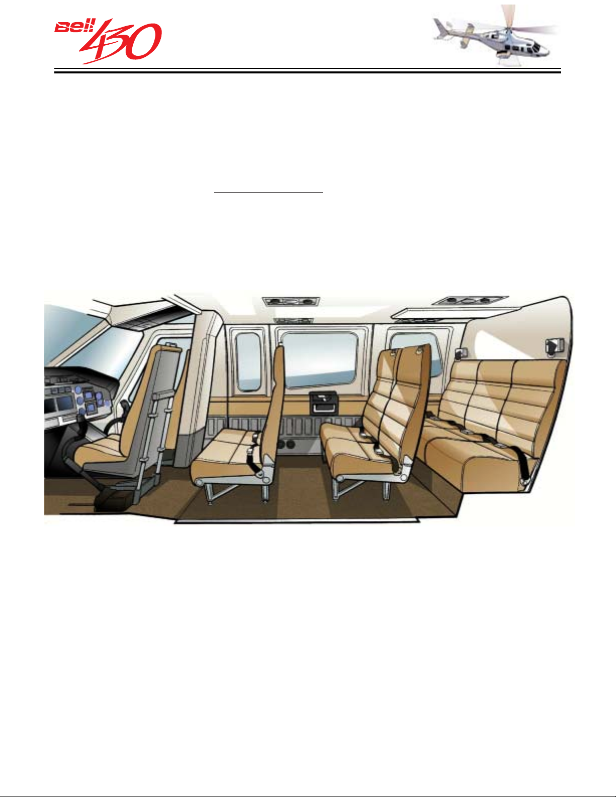
Standard Seating
seat belts and single strap shoulder harness and inertia reel, arranged with two rows
of two, and one row of three forward facing seats. Available in DARK RED, BLUE, BROWN,
or GRAY fabric covered cushions. (108.6 lbs. [49.3 Kg.] included in the standard
configuration weight.) All leather or vinyl is available as an option. This configurations
also available with optional
passenger seats.
- Seven fabric covered high-backed non-folding seats with individual
energy attenuating (either with or without folding seatbacks)
Corporate Interior-
This optional higher level of interior trim complements the executive
seating, but may also be specified with the standard seating, and includes: Floor covered
with tightly woven wool carpet; Side wall armrests covered in color coordinated leather,
with fine hardwood accent trim; Color coordinated seat belts; Color coordinated leather
covering for the crew and passenger seat backs; Decorative accent fabric covering for
the aft cabin bulkhead and small control column bulkhead. (When installed a net increase
of 10.3 lbs. [4.7 Kg.]).
PRODUCT DATA JANUARY 2003
16
Page 17
THIS ELECTRONIC DOCUMENT MAY HAVE BEEN SUPERCEDED.
THE MOST CURRENT DOCUMENT INFORMATION IS AVAILABLE
THIS IS AN UNCONTROLLED DOCUMENT.
FROM YOUR BELL HELICOPTER TEXTRON REPRESENTATIVE.
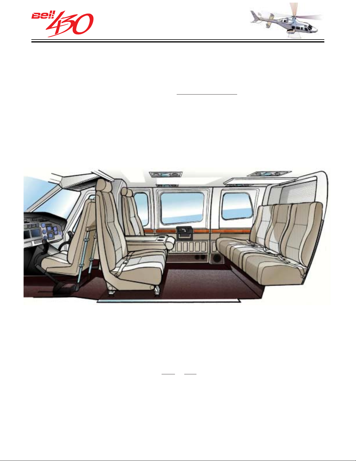
8-Place Corporate Seating
- Six deep bolstered fine wool fabric covered high-backed
seats with individual seat belts and single strap shoulder harness and inertia reel, in
the traditional CLUB arrangement, with one row of three facing rearward, and one row
of three facing forward. Available in eight
color coordinated choices of fabric covered
cushions. (88.0 lbs. [39.9 Kg.]-when installed a net decrease of -3.7 lbs. [-1.7 Kg.]). All
leather is available as an option.
Additional Corporate Seating Arrangements -
five passenger seats in the cabin, and
one or two refreshment / entertainment cabinets
Cabin seating options with four or
are also available;
7-Place Corporate Seating w/one cabinet-[67.5 lbs. (30.6 Kg.), net -22.1 lbs. (-10.0
Kg.)]
6-Place Corporate Seating w/two cabinets-[Customized, net +35 to 50 lbs.(+16 to
25 Kg.)]
PRODUCT DATA JANUARY 2003
17
Page 18
THIS ELECTRONIC DOCUMENT MAY HAVE BEEN SUPERCEDED.
THE MOST CURRENT DOCUMENT INFORMATION IS AVAILABLE
THIS IS AN UNCONTROLLED DOCUMENT.
FROM YOUR BELL HELICOPTER TEXTRON REPRESENTATIVE.
ADDITIONAL CABIN SEATING & INTERIOR CHOICES
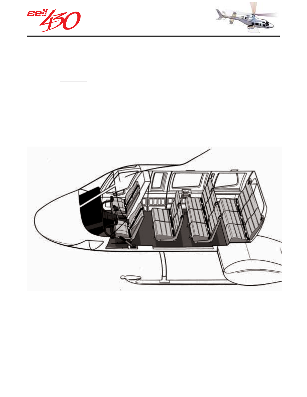
Customized 10-Place Forward Facing Seating
energy attenuating seats with individual seat belts and single strap shoulder harness
and inertia reel, arranged with one row of two, and two rows of three forward facing
seats. The
outboard two seats in the middle row fold forward to provide access to the
rear row. Available in DARK RED, BLUE, BROWN, or GRAY fabric covered cushions.
(134.0 lbs. [60.8 Kg.]-when installed a net increase of 48.3 lbs. [21.9 Kg.]). All leather
or vinyl is available as an option.
- Nine fabric covered high-backed
PRODUCT DATA JANUARY 2003
18
Page 19
THIS ELECTRONIC DOCUMENT MAY HAVE BEEN SUPERCEDED.
THE MOST CURRENT DOCUMENT INFORMATION IS AVAILABLE
THIS IS AN UNCONTROLLED DOCUMENT.
FROM YOUR BELL HELICOPTER TEXTRON REPRESENTATIVE.
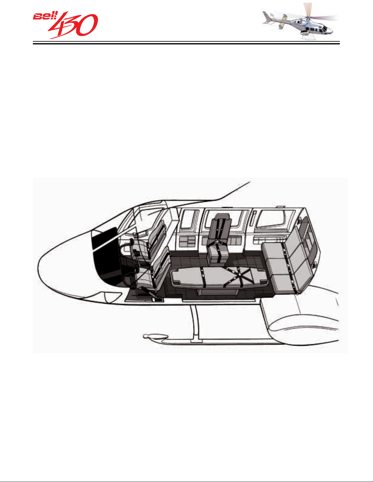
Customized EMS - Single Pivoting Litter [illustrated below] -
Customized EMS interiors
are available to meet a broad range of Hospital Based or Public Agency medical transport
and critical care requirements. The Bell 430 cabin offers ample space for either single
3
or dual pivoting litter installations. The 158 cubic foot (4.5 M
) cabin volume provides
an unmatched work area for multiple medical attendants, with care provided at the
head of the patient, along with a complete complement of fixed and portable life support
3
equipment [An additional 37 cubic feet (1.1 M
) of space located in the cabin accessible
baggage compartment].
PRODUCT DATA JANUARY 2003
19
Page 20
THIS ELECTRONIC DOCUMENT MAY HAVE BEEN SUPERCEDED.
THE MOST CURRENT DOCUMENT INFORMATION IS AVAILABLE
THIS IS AN UNCONTROLLED DOCUMENT.
FROM YOUR BELL HELICOPTER TEXTRON REPRESENTATIVE.
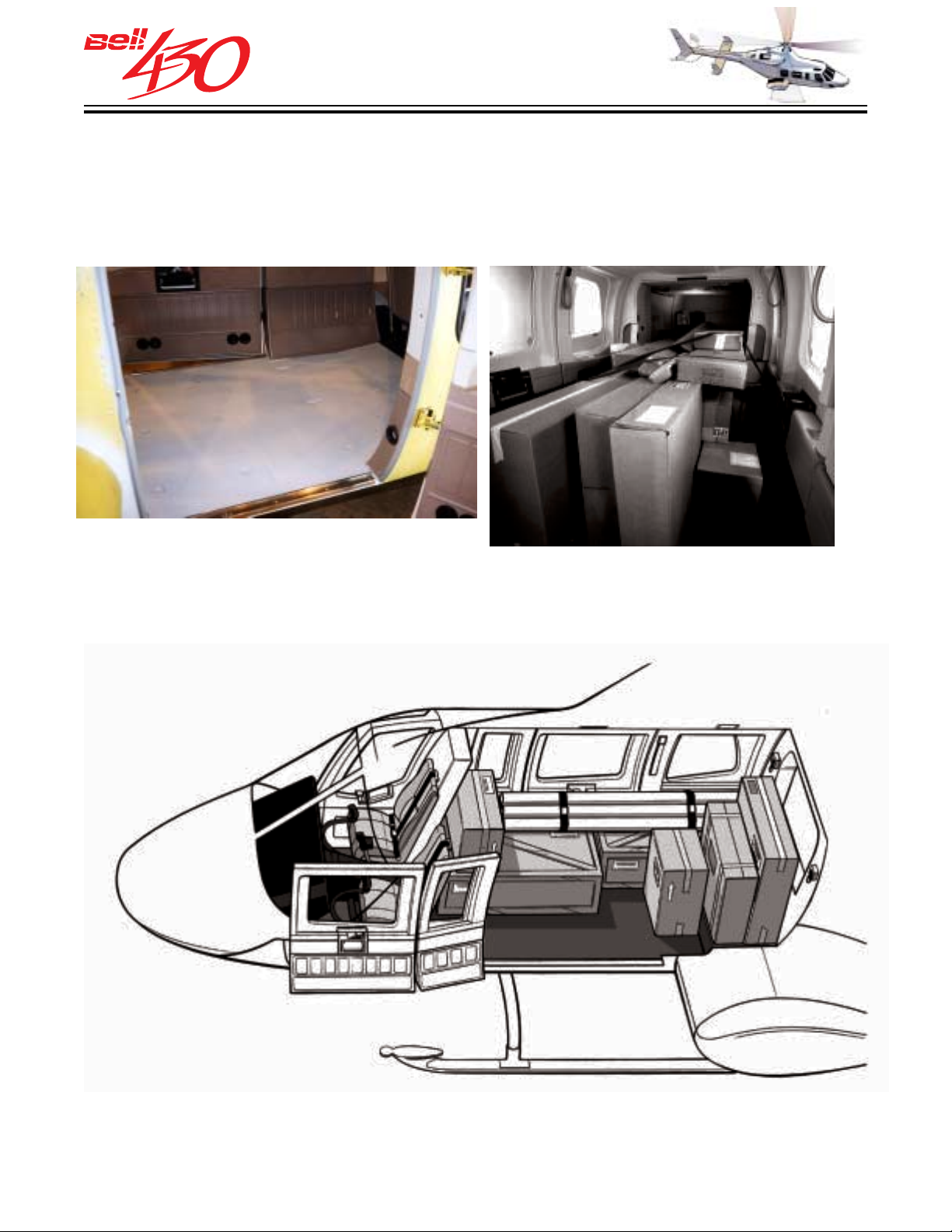
CARGO
When cargo is transported, it may be secured against shifting by attachment of straps
and tie-down rings to the 16 recessed studs found in the cabin floor.
The studs are all stressed for maximum loads of 1134 kilograms (2500 pounds) force,
from perpendicular to 30° in any direction.
PRODUCT DATA JANUARY 2003
20
Page 21
THIS ELECTRONIC DOCUMENT MAY HAVE BEEN SUPERCEDED.
THE MOST CURRENT DOCUMENT INFORMATION IS AVAILABLE
THIS IS AN UNCONTROLLED DOCUMENT.
FROM YOUR BELL HELICOPTER TEXTRON REPRESENTATIVE.
SOUNDPROOFIN G
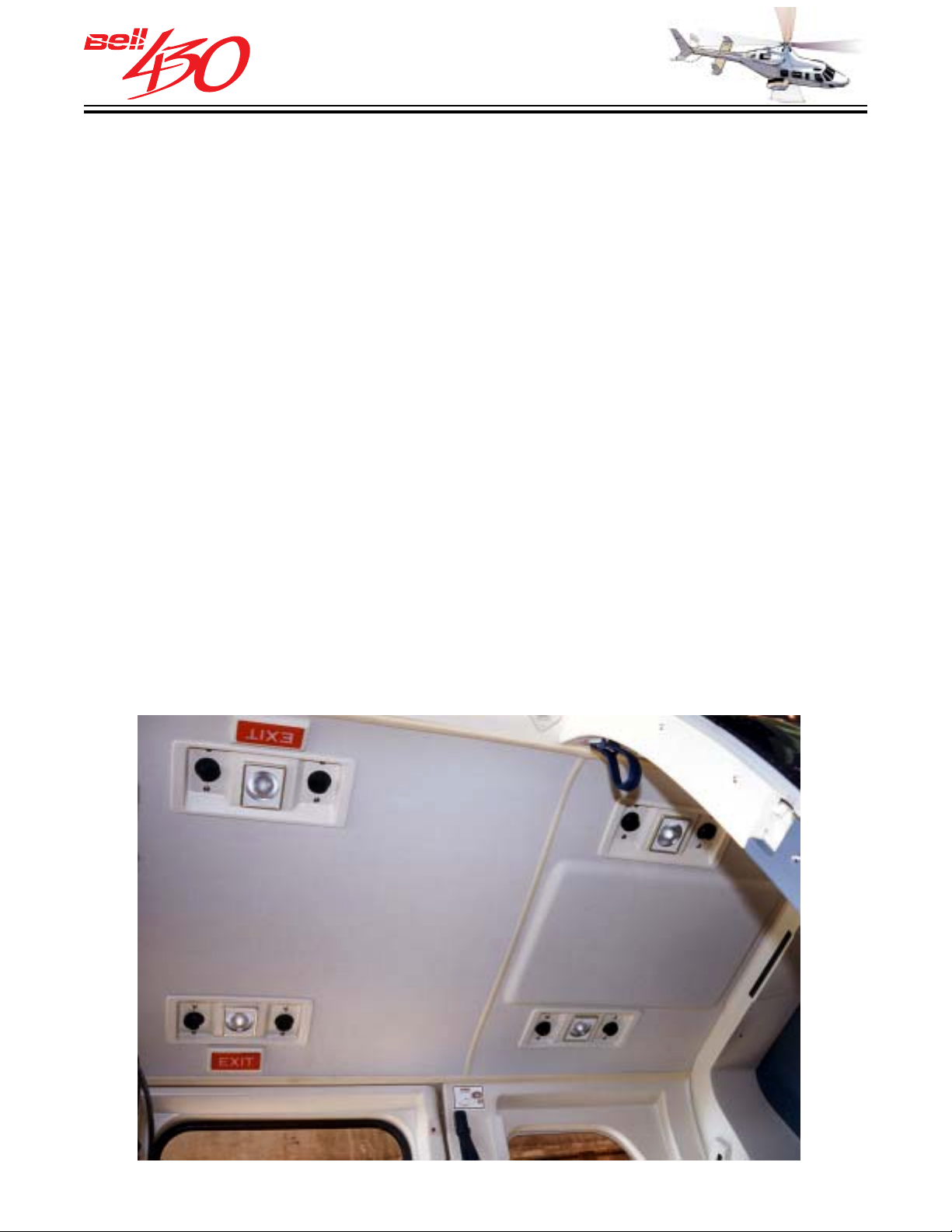
A highly effective soundproofing installation has been engineered for the Bell 430,
and is provided at no additional cost, unless the customer declines its installation.
This provides the customer flexibility where non-Bell interior completions are planned,
or utility operations require the minimum aircraft empty weight / maximum available
payload. The Basic Soundproofing Installation reduces the noise entering the cabin
from the engine and transmission compartments. The soundproofing material consists
of a heavy duty blanket which fits between the headliner and interior trim panels, and
the airframe. The blanket is constructed from alternating layers of sound-attenuating
composite foam, lead foil, and vinyl covered fiberglass batting. Access panels and
bulkhead passages for wiring, ducting, and plumbing are sealed to eliminate extraneous
sound paths.
The installation is compatible with only the STANDARD INTERIOR TRIM. The installation
is not compatible with the optional CORPORATE INTERIOR TRIM or with highly
customized interior completions (such as "COCOON" isolation-type interiors).
The increase in weight with the soundproofing installed is 43.0 kilograms (95.0 pounds).
If the optional auxiliary fuel tank is also installed, the weight increase is 43.2 kilograms
(95.3 pounds).
STANDARD SOUNDPROOFING BEHIND INTERIOR TRIM PANELS REDUCES
NOISE IN THE CABIN FROM THE ENGINES AND TRANSMISSION
[SOUNDPROOFING WEIGHT IS NOT INCLUDED
IN THE STANDARD CONFIGURATION WEIGHT]
PRODUCT DATA JANUARY 2003
21
Page 22
THIS ELECTRONIC DOCUMENT MAY HAVE BEEN SUPERCEDED.
THE MOST CURRENT DOCUMENT INFORMATION IS AVAILABLE
THIS IS AN UNCONTROLLED DOCUMENT.
FROM YOUR BELL HELICOPTER TEXTRON REPRESENTATIVE.
CREW COMPARTMENT
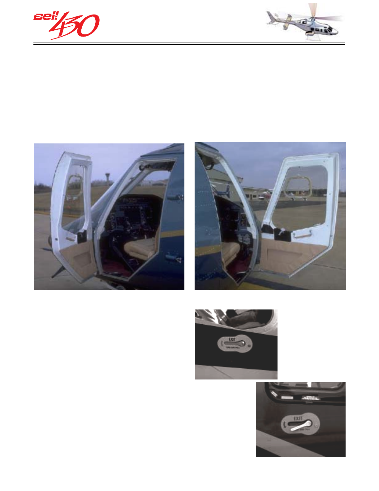
Access to the crew compartment is provided on either side through large doors which are hinged at the forward edge. The doors are secured by a three-point / dual-action latching system and feature full perimeter sealing against wind noise or water leaks.
A hinged metal strap, with a strong spring action , is mounted on the bottom edge of the
door to hold it in the open position. The external door handles are flush-mounted ,
spring-loaded levers, which are easy to grasp and turn. The internal handles are of the lift-up type, with an adjacent hinged assist handle. A common keyed lock is shared with the cabin/baggage doors.
DOCUMENT STOWAGE
Provisions for stowage of documents /
equipment during flight are included. The
following list of stowage requirements are
provided for: Operators Manual, Maps,
Approach Plates / Airport Directories, Flight
Computer / Portable GPS. Additionally,
provisions for the aircraft log book are
available.
PRODUCT DATA JANUARY 2003
22
Page 23

THIS ELECTRONIC DOCUMENT MAY HAVE BEEN SUPERCEDED.
THE MOST CURRENT DOCUMENT INFORMATION IS AVAILABLE
THIS IS AN UNCONTROLLED DOCUMENT.
FROM YOUR BELL HELICOPTER TEXTRON REPRESENTATIVE.
GLASS WINDSHIELDS
Excellent visibility is provided in the crew
compartment by two large glass
windshields and acrylic windows in the
doors, lower nose, and roof. Each crew
door window has a clear vision window
in it's upper center section. The small
window is hinged at the bottom, latched at
it's top, and is sealed for protection against
wind and water.
SKYLIGHT
STANDARD GLASS WINDSHIELDS
STANDARD WINDSHIELD WIPERS
CLEAR VISION WINDOW
CHIN WINDOW
WINDSHIELD WIPERS
A windshield wiper is installed on each windshield. The wipers operate in
synchronization and are controlled by a single switch located on the overhead console.
The switch has four positions, HIGH, LOW, OFF, AND PARK.
PRODUCT DATA JANUARY 2003
23
Page 24
THIS ELECTRONIC DOCUMENT MAY HAVE BEEN SUPERCEDED.
THE MOST CURRENT DOCUMENT INFORMATION IS AVAILABLE
THIS IS AN UNCONTROLLED DOCUMENT.
FROM YOUR BELL HELICOPTER TEXTRON REPRESENTATIVE.
CREW SEATING FEATURES
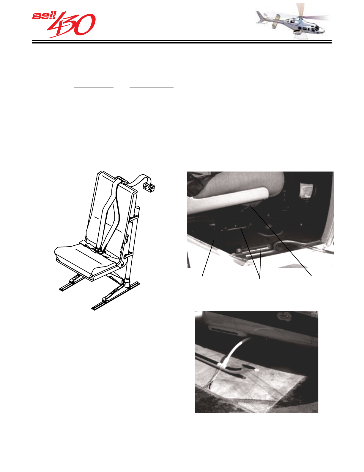
Energy attenuating bucket seats are provided for the pilot and left front passenger.
These seats are upholstered with flame retardant materials and are individually
adjustable
to rails built into the floor and allow forward / rearward movement up to 11.4 centimeters
(4.5 inches), locking every 2 centimeters (0.8 inches). The control lever is on the right
lower seat support. Each seat has its own seat belt and dual-shoulder harness with
inertia reel. The metal buckle of the lap belts accept the clips at the ends of the shoulder
harness straps. One release motion serves to disengage the buckle and straps. The
inertia reel locks automatically to restrain the seat occupant when it senses sudden deceleration.
Each of the crew seats weighs approximately 12.7 kilograms (28 pounds).
fore and aft and up and down. Attachments on the bottom of the seats fit on
The seat back is supported by three
vertical columns, which permit up and
down adjustment of up to 8.9 centimeters
(3.5 inches). A lever under the right forward
edge of the seat controls the movement,
while an assist spring in the central column
make upward adjustment easy. The central
column also contains frangible material
which absorbs energy and allows the seat
to stroke downward in the event of severe
impact. The seats are designed to begin
absorbing energy as a 77 kilogram (170
pound) mass reaches 14.5 g's downward
acceleration.
FWD/AFT
RELEASE
MOUNTING
RAILS
UP / DOWN
RELEASE
A crew step built in to the forward tip of the skid landing gear allows easy entrance
and exit.
PRODUCT DATA JANUARY 2003
24
Page 25
THIS ELECTRONIC DOCUMENT MAY HAVE BEEN SUPERCEDED.
THE MOST CURRENT DOCUMENT INFORMATION IS AVAILABLE
THIS IS AN UNCONTROLLED DOCUMENT.
FROM YOUR BELL HELICOPTER TEXTRON REPRESENTATIVE.
COCKPIT FEATURES
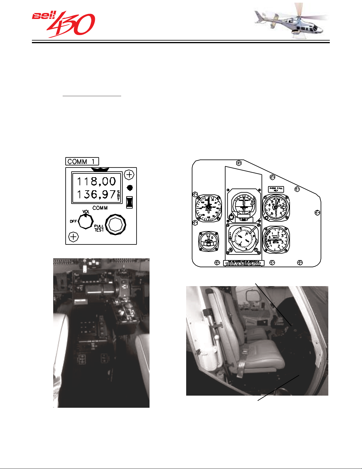
The standard instrument panel is equipped with the basic VFR flight instruments with ample space to add a wide selection of options. Visibility forward and to the side is excellent due to the panel's low, compact design. The standard VHF-AM communications
system (
two-way amplitude-modulated voice communications within the frequency range of
118.000 MHz to 135.975 MHz. The radio's control head is located on the upper center
section of the instrument panel. The remote mounted transceiver unit is located in the
nose avionics compartment and the antenna is on the aircraft belly. The transmit function
is controlled by a switch on the cyclic stick and the floor mounted foot switch.
VHF comm No.1) is a King KTR-908 lightweight airborne radio. It provides
VHF COMM 1 CONTROL HEAD PILOTS INSTRUMENTS [STANDARD
ELECTROMECHANICAL]
PILOT CYCLIC TRANSMIT SWITCH
FLOOR TRANSMIT SWITCH
A center pedestal between the two cockpit seats contains the pilots' ICS control panel,
pilot and left seat ICS / radio foot switch selectors, and gyrocompass control switch.
The remaining space is available for optional equipment.
PRODUCT DATA JANUARY 2003
25
Page 26
THIS ELECTRONIC DOCUMENT MAY HAVE BEEN SUPERCEDED.
THE MOST CURRENT DOCUMENT INFORMATION IS AVAILABLE
THIS IS AN UNCONTROLLED DOCUMENT.
FROM YOUR BELL HELICOPTER TEXTRON REPRESENTATIVE.
COCKPIT FURNISHINGS
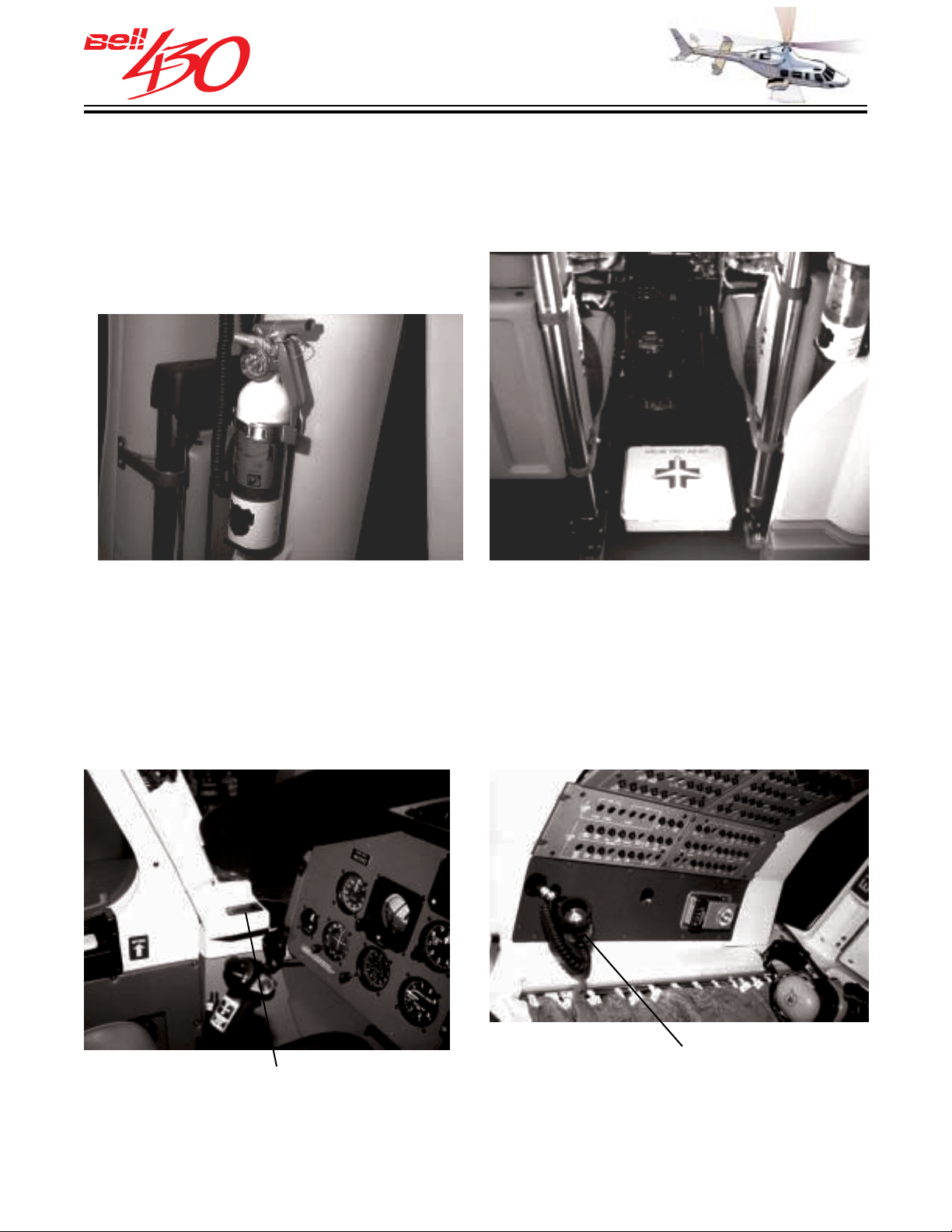
A hand-portable Halon fire extinguisher is located in the cabin. Installed on the vertical
control tunnel's left side in a quick-release bracket, it is readily accessible to the pilot
or passengers. A first aid kit is mounted in between the two cockpit seats.
FIRE EXTINGUISHER
FIRST AID KIT
Two ash trays, one on each side of the cockpit, are located near the forward door posts
at arm level. An aircraft DC electric powered cockpit utility light is located at the rear
of the overhead control panel. It may be removed from its mounting and used by either
crew member by means of its coiled cord.
UTILITY LIGHT
[ GRIMES LIGHT ]CREW ASH TRAY
PRODUCT DATA JANUARY 2003
26
Page 27
THIS ELECTRONIC DOCUMENT MAY HAVE BEEN SUPERCEDED.
THE MOST CURRENT DOCUMENT INFORMATION IS AVAILABLE
THIS IS AN UNCONTROLLED DOCUMENT.
FROM YOUR BELL HELICOPTER TEXTRON REPRESENTATIVE.
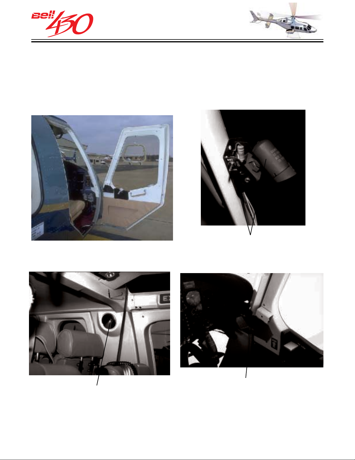
Map pockets are located in the lower portion of each crew door. An approach plate holder and directable map light are located on the pilots' door. The approach plate
holder swings up into position near the standby magnetic compass, directly below the
map light.
DOOR MAP POCKET
SAFETY MIRROR
MAP LIGHT IS
DIRECTABLE
AND DIMABLE
APPROACH PLATE HOLDER
SWINGS AWAY IF NOT NEEDED
A convex safety mirror on the left inside door post allows the pilot to observe cabin
security / loading passengers at a glance, with a minimum of effort, and upper body
movement.
PRODUCT DATA JANUARY 2003
27
Page 28
THIS ELECTRONIC DOCUMENT MAY HAVE BEEN SUPERCEDED.
THE MOST CURRENT DOCUMENT INFORMATION IS AVAILABLE
THIS IS AN UNCONTROLLED DOCUMENT.
FROM YOUR BELL HELICOPTER TEXTRON REPRESENTATIVE.
PASSENGER / CARGO COMPARTMENT
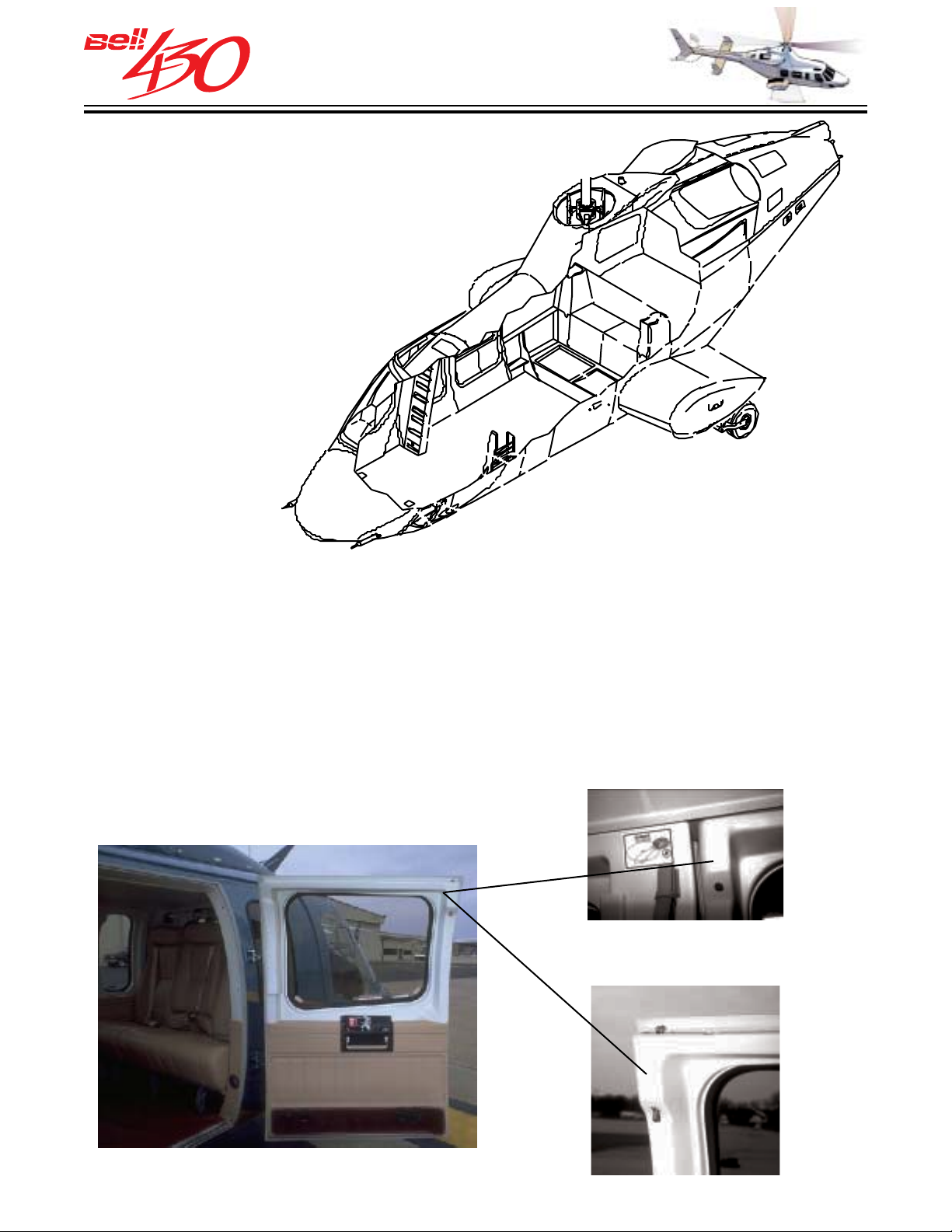
The passenger/cargo compartment
occupies the aft portion of the cabin,
enclosing a volume of 4.5 cubic meters
(158 cubic feet).
Access to the passenger compartment is provided through two wide-opening doors,
one on each side. The doors are hinged at their forward edge, and swing open through
nearly 180° to present an almost unobstructed threshold to the cabin. The door opening
is 0.9 meters (35.6 inches) wide by 1.45 meters (57 inches) high. The three-point
latching system, and slam-closing feature insure a secure, tight fit when closed. The
flush exterior handles, common keyed lock, and full perimeter sealing are the same as for the crew doors. Additionally, a door open indicator pin, visible to the pilot, identifies an unlocked door. The door hinge incorporates hold-open detents at approximately
90° and 115° and a pin-type securing mechanism which enables the door to be locked
in it's forward position.
CLOSED
DOOR OPEN INDICATOR
OPEN
PRODUCT DATA JANUARY 2003
28
Page 29
THIS ELECTRONIC DOCUMENT MAY HAVE BEEN SUPERCEDED.
THE MOST CURRENT DOCUMENT INFORMATION IS AVAILABLE
THIS IS AN UNCONTROLLED DOCUMENT.
FROM YOUR BELL HELICOPTER TEXTRON REPRESENTATIVE.
EMERGENCY EXITS
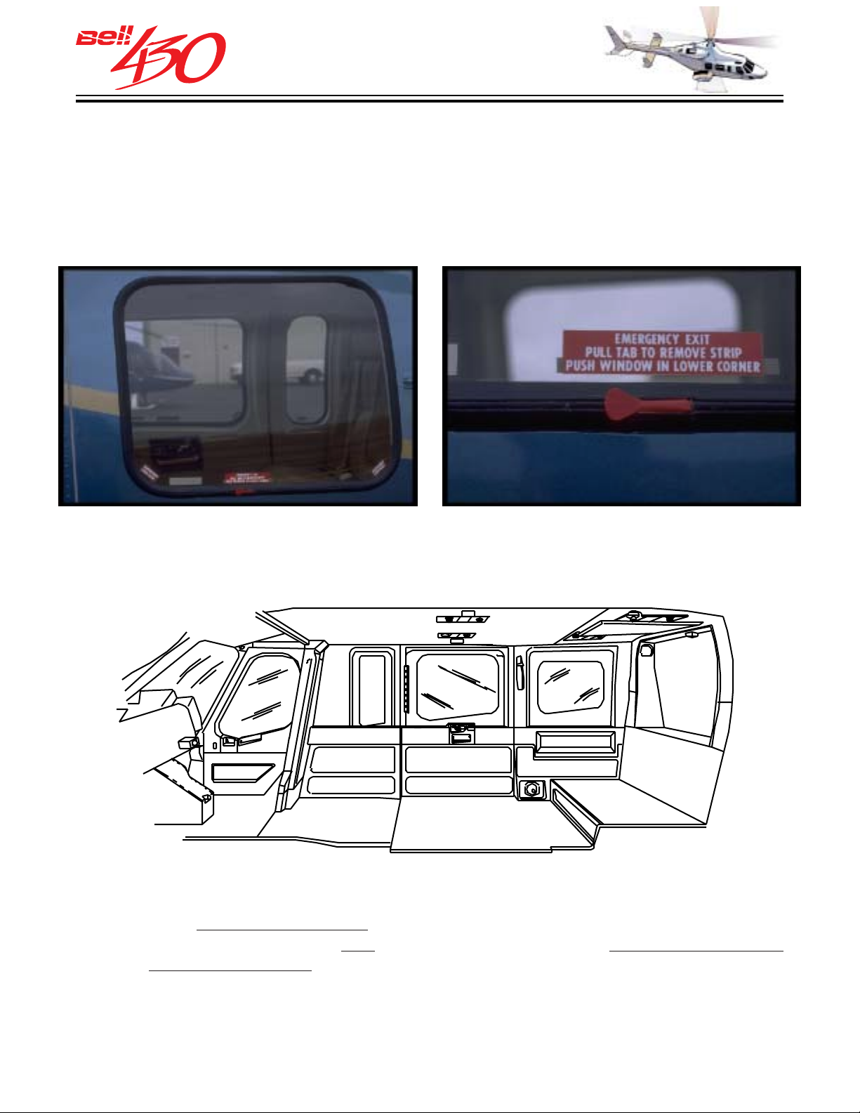
The cabin door windows are fabricated from tinted stretched acrylic, mounted in silicone
rubber molding. The window openings are 0.67 meters (2.2 feet) wide by 0.52 meters
(1.7 feet) high, and serve as emergency exits when pushed out at the lower corners.
CABIN FURNISHINGS
Included in the standard interior trim are; entry assist straps at each cabin door, hinged
door closure assist handles, four ash trays, durable padded VINYL floor covering
or plush
trays are located in the outboard window trim panels, three on each side of the cabin.
The weight of the standard utility interior trim is 33.8 kilograms (74.5 pounds) and is
included in the standard configuration
NYLON loop carpet , hat-rack stowage area, and cabin dome lights. Six ash
.
PRODUCT DATA JANUARY 2003
29
Page 30
THIS ELECTRONIC DOCUMENT MAY HAVE BEEN SUPERCEDED.
THE MOST CURRENT DOCUMENT INFORMATION IS AVAILABLE
THIS IS AN UNCONTROLLED DOCUMENT.
FROM YOUR BELL HELICOPTER TEXTRON REPRESENTATIVE.
STANDARD SEATING
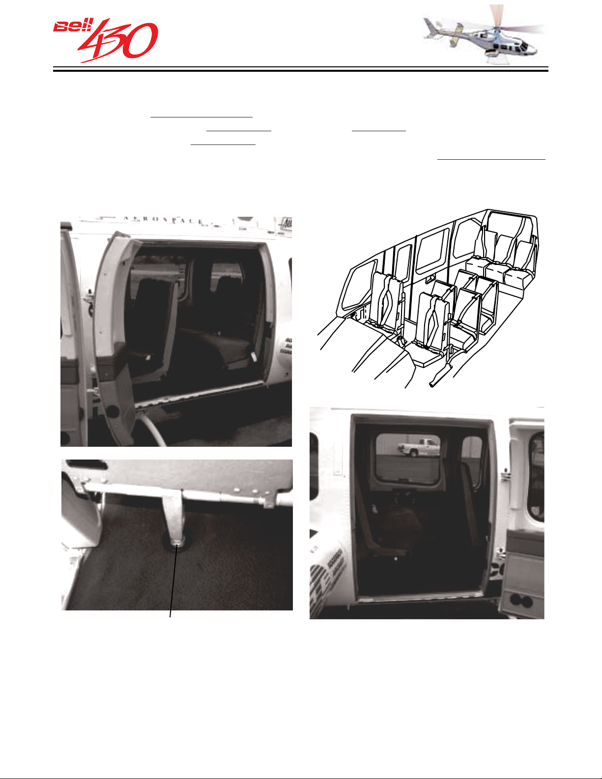
The nine place[ seven cabin seat ]utility interior is standard. There are three rows
of cabin passenger seats,
and one forward). The
belts / shoulder harnesses meet the latest FAR specifications for occupant restraint.
The seats are comfortably upholstered in flame retardant fabric, and feature advanced
ergonomic design.
one aft row of three, and two rows of two (one intermediate
lightweight folding seats with high backs and individual lap
FLOOR FITTING
The seats are secured to the floor of the cabin with quick-release / positive locking
ring-on-stud type fasteners. They are easily removed in only moments to convert the
cabin for carriage of large or bulky cargo. The average weight for each two seat module
is 15.9 kilograms (35 pounds). The average weight for each individual rear row seat
is 6.8 kilograms (15 pounds). The total weight of the standard seating is 49.3 kilograms
(108.6 pounds).
PRODUCT DATA JANUARY 2003
30
Page 31
THIS ELECTRONIC DOCUMENT MAY HAVE BEEN SUPERCEDED.
THE MOST CURRENT DOCUMENT INFORMATION IS AVAILABLE
THIS IS AN UNCONTROLLED DOCUMENT.
FROM YOUR BELL HELICOPTER TEXTRON REPRESENTATIVE.
The long cabin has room for comfortable seat pitch in the standard 9 place seating arr angement.
The standard arrangement has:
•Two seats in the cockpit
•Two seats in the front row of the passenger cabin
•Two seats in the middle row, and
•Three seats in the aft row.
Seat pitch is generous:
•35.9 inches, 91.2 centimeters, between the crew seats and the front row.
•34.8 inches, 88.4 centimeters, between the front and middle rows,
•35.6 inches, 91.2 centimeters, between the middle and aft rows.
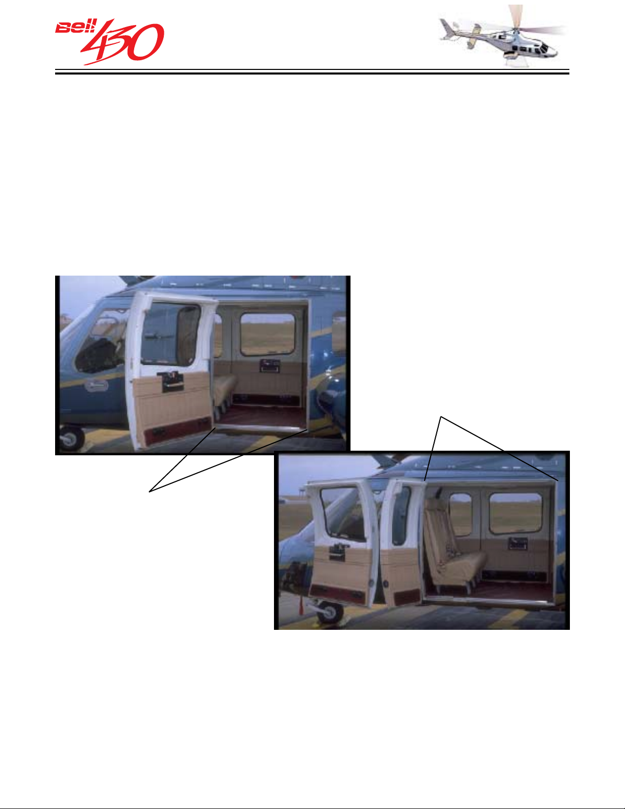
PHOTOS FOR ILLUSTRATION
OF DOOR WIDTH ONLY
[SEATS SHOWN ARE OPTIONAL
8-PLACE
CORPORATE CONFIGURATION]
OPTIONAL
LITTER DOOR
54 INCHES [1.37 METERS]
WIDE ACCESS
STANDARD
36 INCHES [ 0.92 METERS]
WIDE ACCESS
These seat pitch values are well in e xcess of the 30 to 32 inches found in the coach section of jet
airliners. The standard left and right cabin doors open to an unobstructed area of 3 feet, 92
centimeters, wide by 4 feet, 122 centimeters, high. A n optional hinged panel door kit is avail-
able that consists of two doors on the left side of the cabin. The main door is identical to the right
one. It is attached with a hinge to a panel door in a manner similar to the Bell LongRanger series.
This panel door also is hinged, and both doors can s wing open to give a 54 inch, 137 centimeter,
access to the cabin to facilitate litter or bulky cargo loading.
PRODUCT DATA JANUARY 2003
31
Page 32
THIS ELECTRONIC DOCUMENT MAY HAVE BEEN SUPERCEDED.
THE MOST CURRENT DOCUMENT INFORMATION IS AVAILABLE
FROM YOUR BELL HELICOPTER TEXTRON REPRESENTATIVE.
FLIGHT CONTROLS
THIS IS AN UNCONTROLLED DOCUMENT.
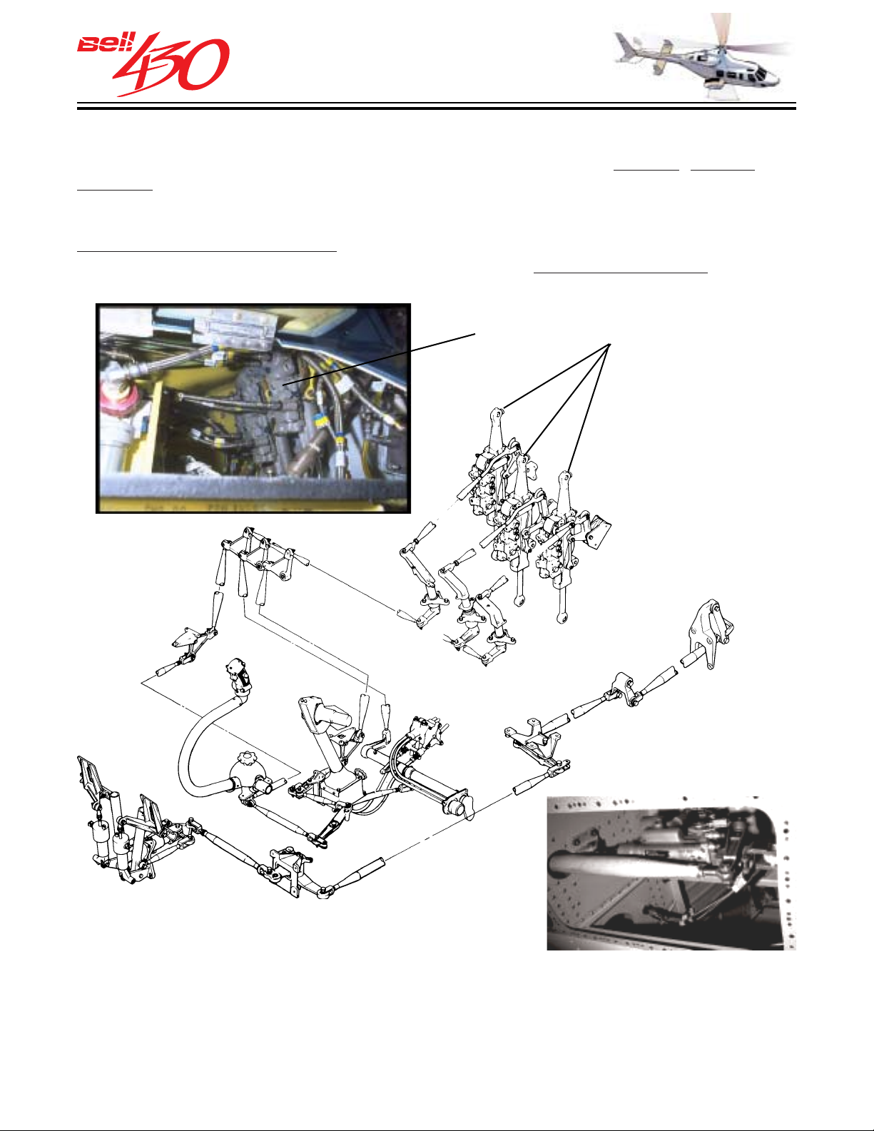
Conventional helicopter flight controls are provided to control
attitude, altitude, and direction. Inputs from the cyclic and collective controls are transmitted to the MAIN ROTOR, and inputs to the anti-torque (directional control) pedals are transmitted to
the TAIL ROTOR. The flight control system is a direct mechanical linkage, using only
push-pull tubes and bellcranks. All bearings in the tubes and bellcranks are spherical,
self-aligning, and require no lubrication. There are no cables or pulleys to require
tension adjustments or fraying inspections.
CYCLIC AND COLLECTIVE SERVOS
TAIL ROTOR SERVO
HYDRAULIC BOOSTED CONTROL
The CYCLIC and COLLECTIVE controls have dual hydraulic servo actuators , and
the DIRECTIONAL controls have a single hydraulic servo actuator to amplify the
force of the pilot's inputs. The hydraulic servo actuators also prevent feedback forces
from the rotor systems from moving the pilot's flight controls.
PRODUCT DATA JANUARY 2003
32
Page 33
THIS ELECTRONIC DOCUMENT MAY HAVE BEEN SUPERCEDED.
THE MOST CURRENT DOCUMENT INFORMATION IS AVAILABLE
THIS IS AN UNCONTROLLED DOCUMENT.
FROM YOUR BELL HELICOPTER TEXTRON REPRESENTATIVE.
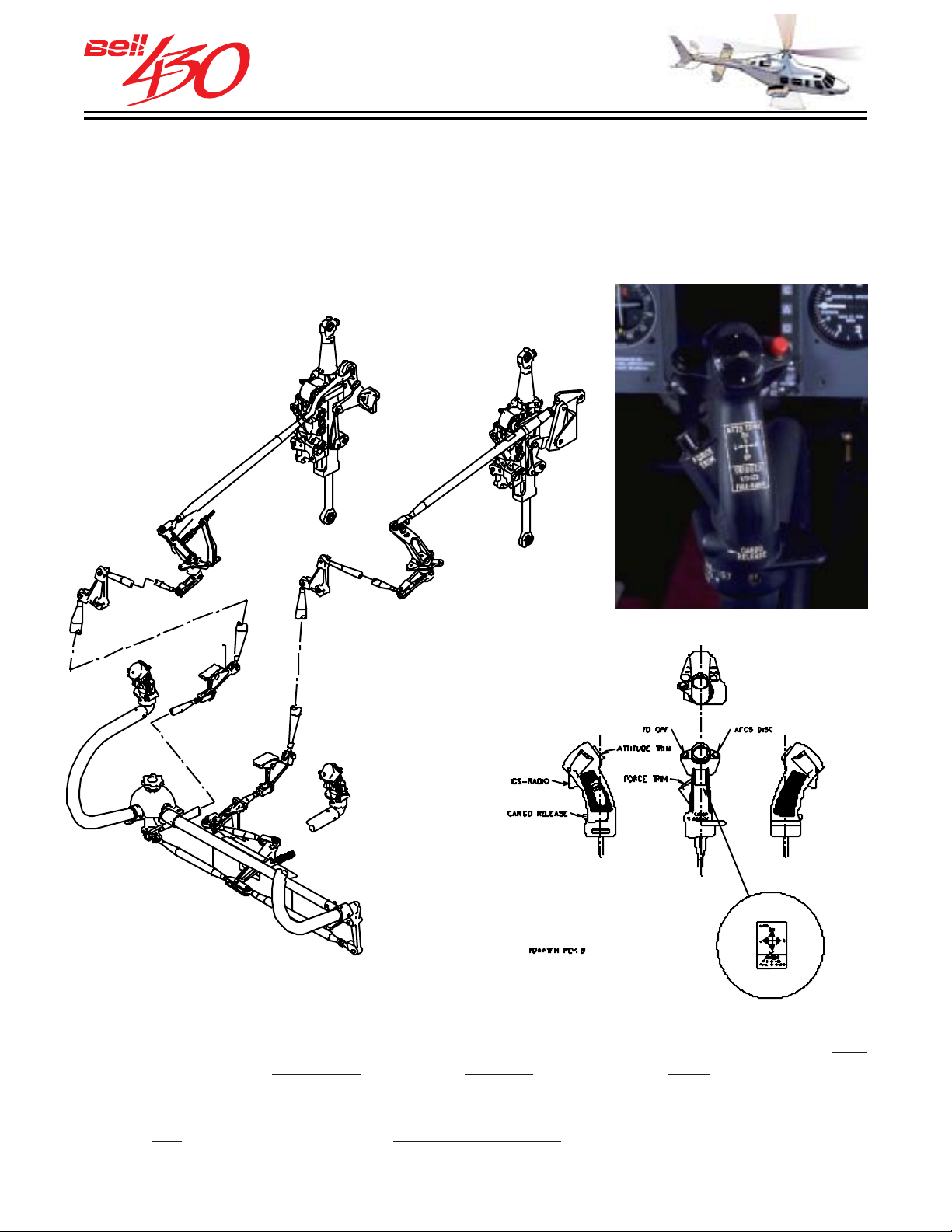
CYCLIC CONTROL SYSTEM
The cyclic control stick attaches to the floor, directly in front of the pilot's seat. A
direct linkage beneath the floor separates fore and aft, and lateral inputs, and transmits
them through the vertical control tunnel to the respective servo actuators. Provisions
to connect the optional dual/copilot control kit are standard.
CYCLIC STICK GRIP
The cyclic grip has a two-position radio "trigger" switch on it's forward face. The first
detent activates the
transmitter. Space is provided on the grip for additional switches used to control optional
equipment. A friction adjustment control, located at the cyclic's base, allows the
pilot to
PRODUCT DATA JANUARY 2003
set the desired amount of control resistance .
intercom, while the second activates the VHF communications
33
Page 34
THIS ELECTRONIC DOCUMENT MAY HAVE BEEN SUPERCEDED.
THE MOST CURRENT DOCUMENT INFORMATION IS AVAILABLE
THIS IS AN UNCONTROLLED DOCUMENT.
FROM YOUR BELL HELICOPTER TEXTRON REPRESENTATIVE.
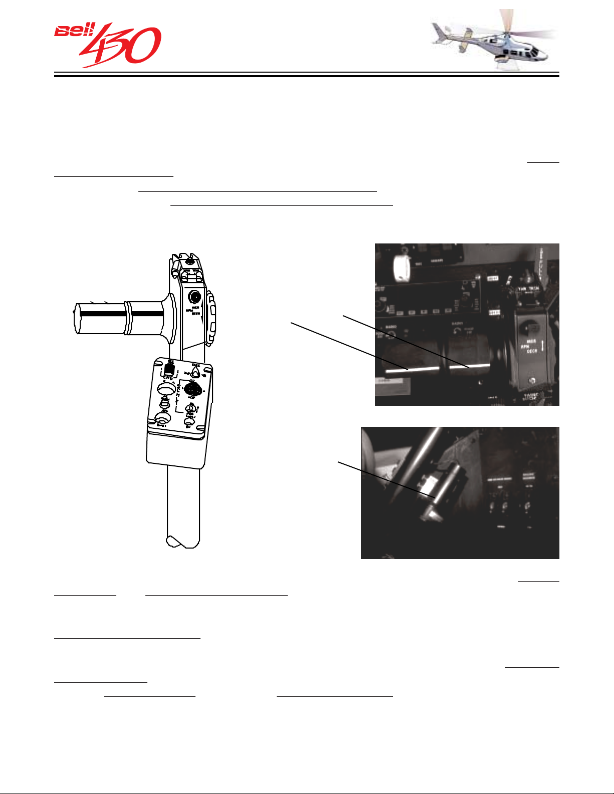
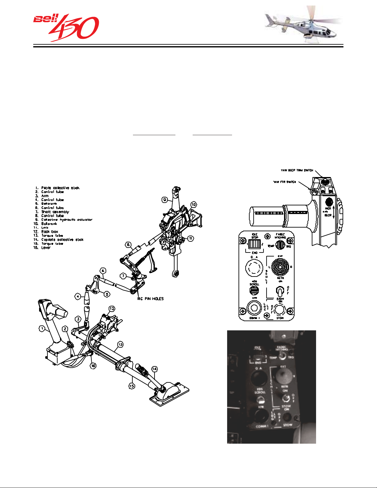
COLLECTIVE CONTROL SYSTEM
The collective control lever attaches to the cabin floor on the pilot's left, at the base of
the pedestal. A direct linkage, beneath the floor, transmits collective input through
the vertical control tunnel to the collective servo actuator. Provision to connect the
optional dual/copilot control kit is standard. The standard collective-mounted
grip engine throttles are arranged horizontally on the left side of the control head, and
align directly with their respective engine instruments . They are always available for
pilot management,
without releasing the collective lever. The left/right arrangement
corresponds to the physical engine location; left - No.1/left- No.2/right. This insures
correct identification of engine/throttle.
THROTTLES
NO. 1 / NO. 2
twist-
STICK
SHAKER
The Bell 430 collective lever incorporates some unique design features which reduce
pilot effort and enhance safe operation. The collective operates in a near horizontal
arc (i.e.; increasing collective pitch equates to more rearward than upward motion of
the lever) perpendicular to any vertical rotor system vibrations, which eliminates any
pilot induced oscillations . The motion is natural and pilot control inputs are instinctively
correct. The throttles are canted aft about 10° and form a comfortable and natural left
hand grip. Bold white lines on the finely ribbed black rubber grips visibly
indicates
throttle position throughout their range. Throttle motion is conventional and instinctive;
rotating
up and forward to open and down and rearward to close. A stick shaker is
located on the collective lever, and when an impending OVERTORQUE condition is
sensed by the IIDS it functions (vibrates) to warn the pilot to reduce power. A shaker
test button is located on the pedestal.
PRODUCT DATA JANUARY 2003
34
Page 35
THIS ELECTRONIC DOCUMENT MAY HAVE BEEN SUPERCEDED.
THE MOST CURRENT DOCUMENT INFORMATION IS AVAILABLE
THIS IS AN UNCONTROLLED DOCUMENT.
FROM YOUR BELL HELICOPTER TEXTRON REPRESENTATIVE.
Throttle friction adjustment is provided by a large knurled ring on the right side of the
collective lever. The engine RPM (N
) control is located at the top of the collective.
P
This two-way RPM "beep" switch serves to adjust RPM of both engines simultaneously when moved fore/aft (for fine adjustment of rotor RPM). A collective control box is
attached just below the throttles. It contains the FADEC MATCHING switch (which selects either torque or temperature matching for the engines), the idle stop release
switch (which permits the respective throttles to advance past idle or to be closed),
the landing/searchlight's
on-off-stow and directional switches, the VHF comm No.1
standby frequency transfer button, and the IIDS Scroll switch (which allows the pilot
to advance through the IIDS secondary display pages). There is extra space provided
for optional equipment controls.
PRODUCT DATA JANUARY 2003
35
Page 36
THIS ELECTRONIC DOCUMENT MAY HAVE BEEN SUPERCEDED.
THE MOST CURRENT DOCUMENT INFORMATION IS AVAILABLE
THIS IS AN UNCONTROLLED DOCUMENT.
FROM YOUR BELL HELICOPTER TEXTRON REPRESENTATIVE.
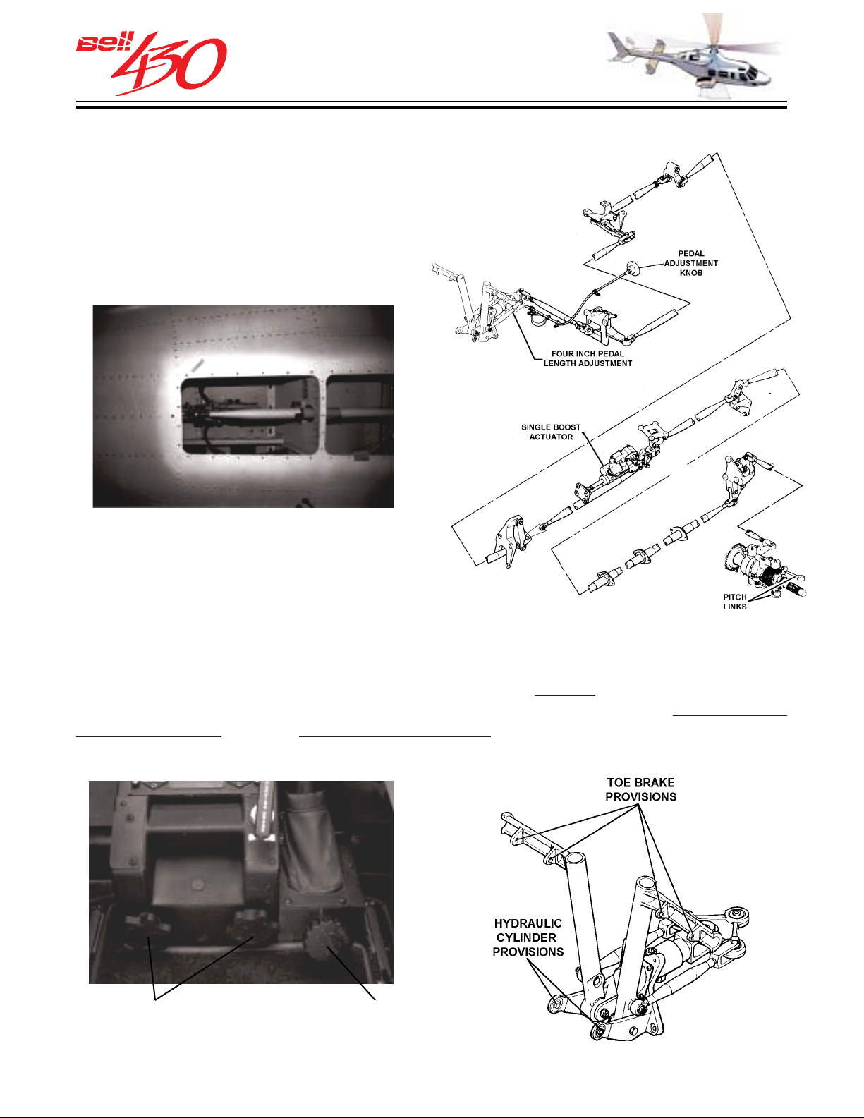
ANTI-TORQUE [ DIRECTIONAL CONTROL ] SYSTEM
This system transmits movement from the
control pedals to the tail rotor. The direct
linkage under the floor transmits input
through the belly control tunnel to the single
servo-actuator and on to the tail rotor.
TAIL ROTOR SERVO
There is a pedal length adjustment knob located at the rear base of the pedestal,
which allows approximately 10.2 centimeters (4 inches)
relative to the pilots feet. Provisions exist for both the addition of the
fore/aft movement of the pedals
optional dual/
copilot control kit, and the hydraulic brake pedals of the optional wheel landing gear.
PEDAL ADJUSTMENT
CONTROL KNOBS
PRODUCT DATA JANUARY 2003
COLLECTIVE
FRICTION
CONTROL
36
Page 37
THIS ELECTRONIC DOCUMENT MAY HAVE BEEN SUPERCEDED.
THE MOST CURRENT DOCUMENT INFORMATION IS AVAILABLE
THIS IS AN UNCONTROLLED DOCUMENT.
FROM YOUR BELL HELICOPTER TEXTRON REPRESENTATIVE.
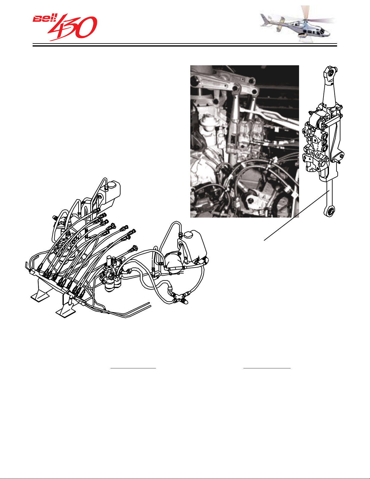
HYDRAULIC SYSTEM
The Bell 430 has two completely
independent hydraulic systems, each with
its own reservoir, variable-delivery pump,
integrated valve and filter module,
temperature and pressure monitoring
sensors, "Quick Disconnect" ground test
fittings, check valves, pressure and return
manifolds, and distribution network. Each
of the variable-delivery pumps is powered
by separate drive quills located on the left
and right freewheeling units of the
transmission.
•EXAMPLE•
The three dual hydraulic servo actuators in the cyclic and collective control system
are operated by both systems, which are designated PC 1 and PC 2. Additionally, the
directional control (ANTI-TORQUE) system servo actuator is powered by PC 1, and
provisions exist for PC 2 to power the optional wheel landing gear retraction mechanism.
Both systems operate
continuously, but may be individually de-energized for functional
preflight system check. Two switches (HYD #1 & HYD#2), located on the overhead
console, control solenoid valves and are connected so that only one system at a time
can be de-energized.
The cyclic and collective servo actuators are mounted on the forward side of the
transmission in order to isolate them from any inputs caused by pylon motion.
The lower half of each servo is powered by PC 1, while the upper halves are powered
by PC 2. The nominal operating pressure of both systems is 10,342 kPa (1500 psi)
throughout the approved temperature range of -54° to +82°C (-65° to +180°F).
PRODUCT DATA JANUARY 2003
37
Page 38
THIS ELECTRONIC DOCUMENT MAY HAVE BEEN SUPERCEDED.
THE MOST CURRENT DOCUMENT INFORMATION IS AVAILABLE
THIS IS AN UNCONTROLLED DOCUMENT.
FROM YOUR BELL HELICOPTER TEXTRON REPRESENTATIVE.
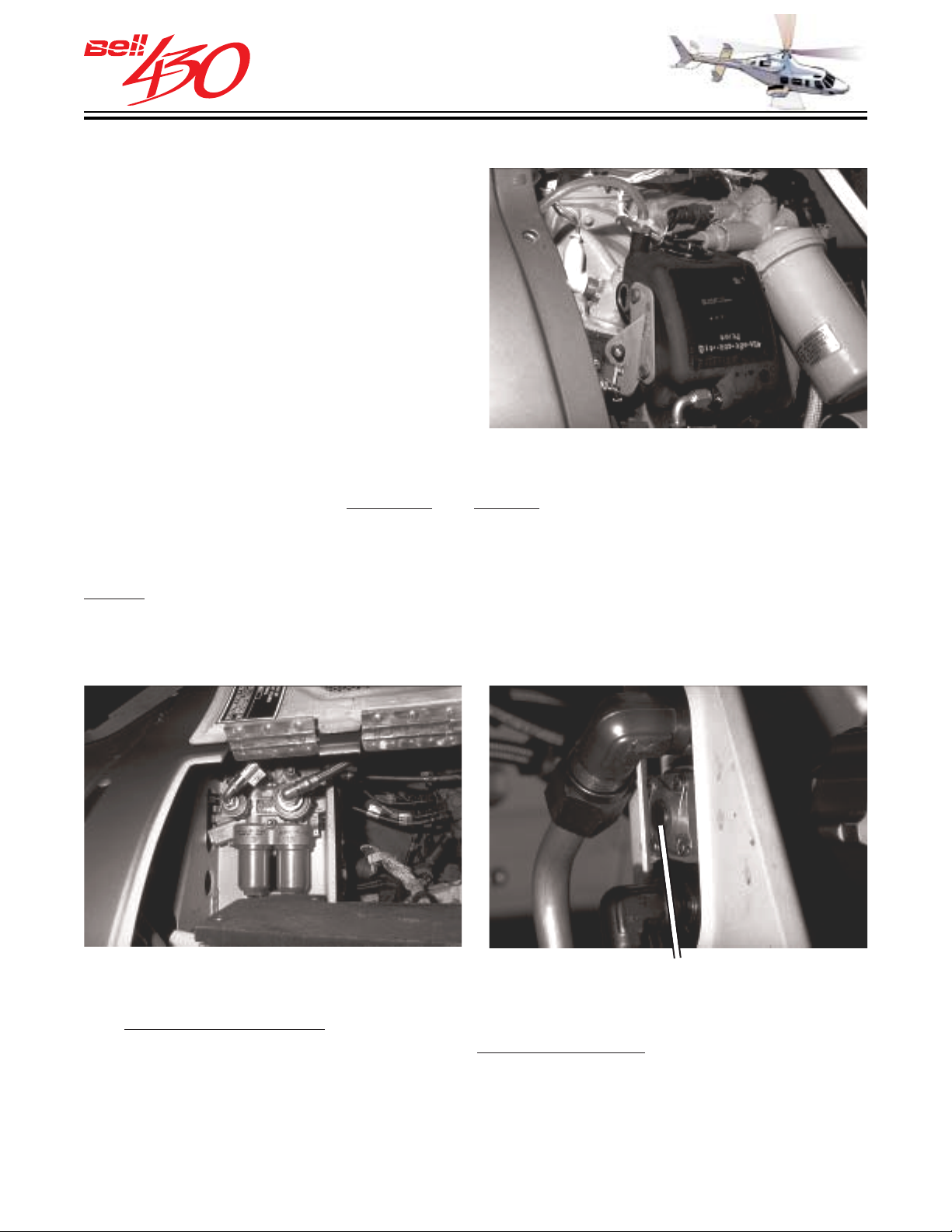
HYDRAULIC RESER VOIRS
The hydraulic reservoirs are mounted on
either side of the transmission. Each tank
has a sight glass to visually check fluid
level. Temperature bulbs in each tank
provide input to the respective hydraulic
display of the IIDS.
HYDRAULIC RESERVOIR
The integrated valve and filter modules are located on each side of the cabin roof.
They contain dual filters,
contamination does not spread to other system components. Both filters have RED indicator buttons which warn of filter obstruction. When the return filter becomes
excessively obstructed a bypass valve opens. Each module incorporates two relief
valves which eliminate residual or thermal induced pressure from the systems after
shutdown. The pumps and reservoirs are coupled to the integrated modules by flexible
hoses with quick disconnect fittings which allow a standard hydraulic ground power
unit (hydraulic mule) to be attached for system maintenance checks.
pressure and return , to insure that a single source of
FILTER MODULE W/"QUICK DISCONNECTS" FILTER BYPASS BUTTON
Each system has two pressure sensors; a pressure switch, and a pressure transmitter.
pressure transmitters are located in the pressure manifolds, and provide input for
The
the TEMP / PRESS display of the IIDS. The pressure switches are on the pressure side
of the integrated modules, and are connected to the hydraulic warning/caution display
of the IIDS. The indication illuminates when system pressure decreases below 6895
kPa (1000 psi). The indication extinguishes when system pressure increases above
8274 kPa (1200 psi).
PRODUCT DATA JANUARY 2003
38
Page 39
THIS ELECTRONIC DOCUMENT MAY HAVE BEEN SUPERCEDED.
THE MOST CURRENT DOCUMENT INFORMATION IS AVAILABLE
THIS IS AN UNCONTROLLED DOCUMENT.
FROM YOUR BELL HELICOPTER TEXTRON REPRESENTATIVE.
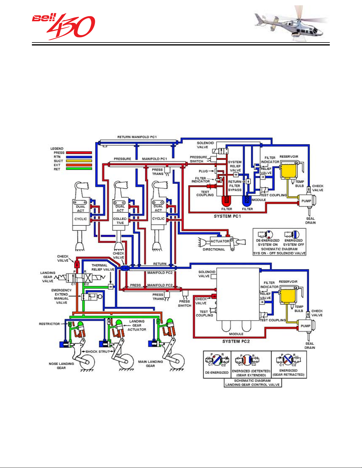
HYDRAULIC SYSTEM SCHEMATIC
[ WHEEL LANDING GEAR CONFIGURATION SHOWN FOR EXAMPLE ONLY
- STANDARD SKID LANDING GEAR CONFIGURATION INCLUDES
PROVISION TO ADD WHEEL SUBSYSTEM ]
PRODUCT DATA JANUARY 2003
39
Page 40
THIS ELECTRONIC DOCUMENT MAY HAVE BEEN SUPERCEDED.
THE MOST CURRENT DOCUMENT INFORMATION IS AVAILABLE
THIS IS AN UNCONTROLLED DOCUMENT.
FROM YOUR BELL HELICOPTER TEXTRON REPRESENTATIVE.
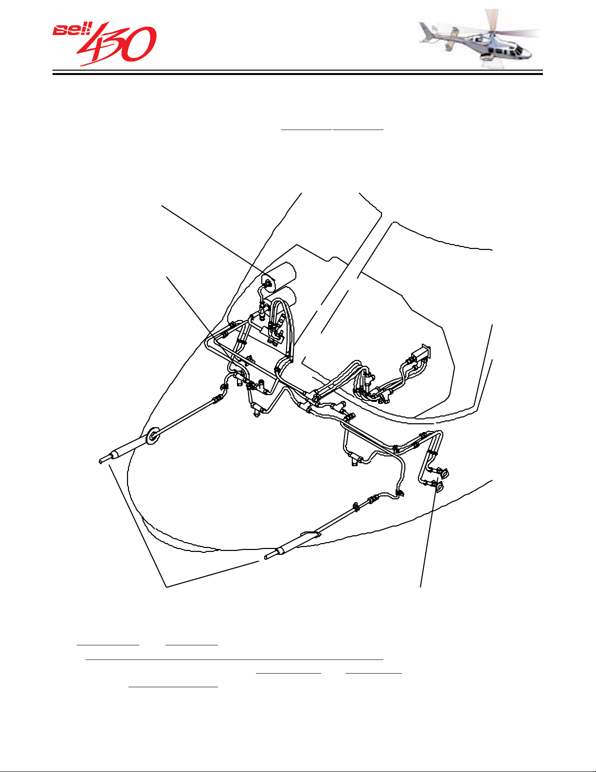
PITOT-S TATIC SYSTEM
The pitot system (ram air pressure) consists of one electrically heated pitot tube on
the left side of the nose, connected to the
air pressure) contains four electrically heated ports, two per side (upper and lower)
located immediately in front of each crew door.
ALTIMETER / AIRSPEED / VERTICAL SPEED
RIGHT STATIC PORTS
airspeed indicator. The static system (ambient
PITOT TUBES
[LEFT SIDE ONLY FUNCTIONAL WITH
OPTIONAL COPILOT INSTRUMENTS]
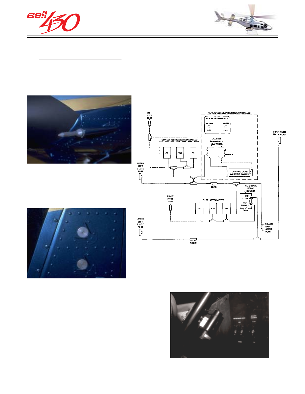
upper right and lower left static ports provide primary equalized ambient pressure
The
LEFT STATIC PORTS
to the airspeed and vertical speed indicators, and altimeter through the alternate static
source switch [PRI position]. The
an alternate
ambient source [ALT position], and include provisions to connect to the
lower right and upper left ports p rov ide the swi tch
optional copilot instruments and optional wheel landing gears' auxiliary pitot-static
system (landing gear warning switch).
PRODUCT DATA JANUARY 2003
40
Page 41
THIS ELECTRONIC DOCUMENT MAY HAVE BEEN SUPERCEDED.
THE MOST CURRENT DOCUMENT INFORMATION IS AVAILABLE
THIS IS AN UNCONTROLLED DOCUMENT.
FROM YOUR BELL HELICOPTER TEXTRON REPRESENTATIVE.
The alternate static source switch is located on the lower right side of the center pedestal.
Since a second external source is provided there in no need for an
which could cause
PITOT TUBE
inaccurate instrument indications.
internal source,
DUAL STATIC PORTS
Additionally, a second pitot tube is installed
standard equipment. Located on the left
as
side of the nose, but not connected
internally, it is included to facilitate
installation of the optional copilot
instrument kit. The pitot-static system is
fitted with condensation drains and
provisions to attach standard flight
instrument ground calibration test
equipment.
PRI / ALT STATIC SOURCE
SELECT SWITCH
PRODUCT DATA JANUARY 2003
41
Page 42
THIS ELECTRONIC DOCUMENT MAY HAVE BEEN SUPERCEDED.
THE MOST CURRENT DOCUMENT INFORMATION IS AVAILABLE
THIS IS AN UNCONTROLLED DOCUMENT.
FROM YOUR BELL HELICOPTER TEXTRON REPRESENTATIVE.
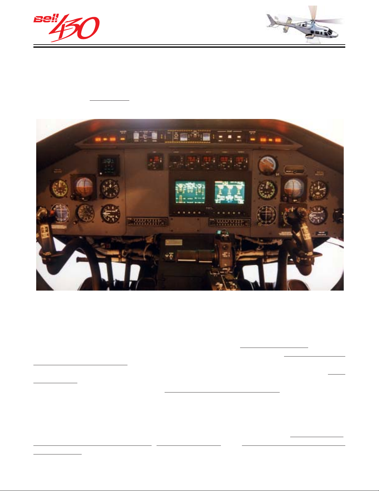
INSTRUMENT PANEL
The instrument panel, which consists of four separate sections, extends across the front of the flight crew compartment. All instruments are front mounted in the panel to make removal / replacement quick and easy. All the instruments are integrally illuminated
with adjustable
side of the instrument panel, are also provided.
blue/ white lighting. Two map lights, located on the door posts on either
INSTRUMENT PANEL LAYOUT WITH SOME OPTIONAL EQUIPMENT SHOWN
Primary flight and navigation instruments are mounted on the right (pilot) section of
the panel, in the conventional "T" presentation, for an easy cross-check. Space is
provided on the left (copilot) section of the panel for the optional
copilot flight and
navigation instrument kit. All aircraft system indications are displayed on the IIDS [Integrated Instrument Display System] located in the center section for easy
observation from either crew seat. The center section also contains space for optional
avionics control heads arranged for convenient viewing/adjustment by pilot or copilot.
Space is also allocated for the optional wheel landing gears' control panels (RETRACT
/ EXTEND). Additionally, a 15 centimeter (six inch) wide column between the IIDS and
copilot group is suitable for placement of standard width panel mounted avionics
customized installations (Loran, Global Positioning, Weather Radar, and other
communications radios, etc.). The top section contains control panels for
engine starting,
fire detection and extinguishing, FADEC functions, and master warning and caution
annunciation.
PRODUCT DATA JANUARY 2003
42
Page 43
THIS ELECTRONIC DOCUMENT MAY HAVE BEEN SUPERCEDED.
THE MOST CURRENT DOCUMENT INFORMATION IS AVAILABLE
THIS IS AN UNCONTROLLED DOCUMENT.
FROM YOUR BELL HELICOPTER TEXTRON REPRESENTATIVE.
INSTRUMENT P ANEL LAYOUT
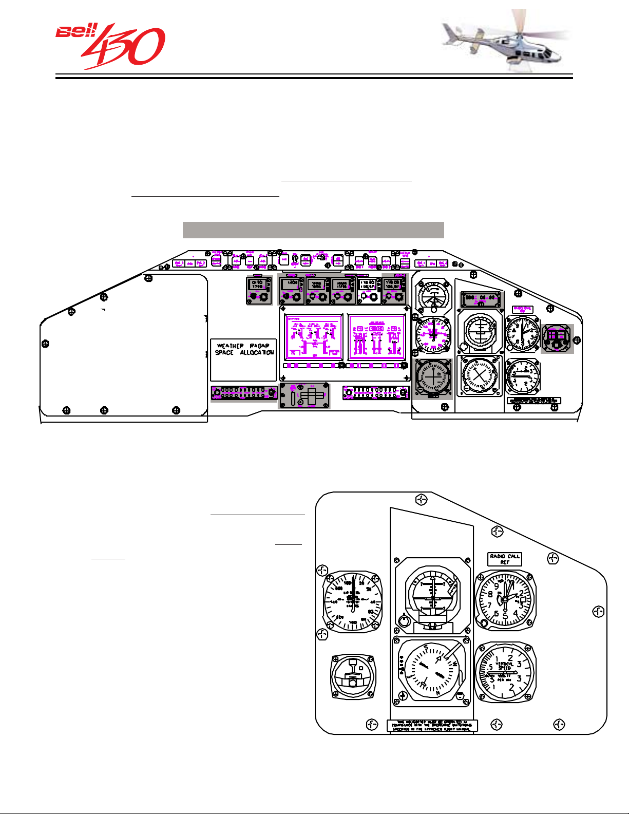
The standard instrument panel in the Bell 430 is fully equipped for VFR (Visual Flight
Rules) flight, day or night. It also has space to install additional communications and
navigation equipment, instruments and indicators necessary to conduct IFR/IMC
(Instrument Flight Rules/Instrument Meteorological Conditions) flight. The illustration
below shows the normal locations for
for selected factory installed options .
OVERALL INSTRUMENT PANEL LAYOUT
[SHOWN WITH OPTIONAL EQUIPMENT SHADED]
standard instruments, as well as space reserved
RIGHT (PI LOT) SECTION
STANDARD ELECTROMECHANICAL PILOT INSTRUMENTS
Operating limitations are clearly indicated
on all electromechanical instruments, with
green, yellow, and red bands on the
or the
bezel. The following instruments are
provided with the standard configuration.
1. AIRSPEED
2. ATTITUDE INDICATOR
3. ALTIMETER
4. VERTICAL SPEED
5. HSI-[WITH COMPASS SYSTEM]
6. TURN AND SLIP
7. STANDBY MAGNETIC COMPASS
(STBY. COMP. NOT SHOWN-SEE NEXT PAGE)
face,
2
1
6
5
3
4
PRODUCT DATA JANUARY 2003
43
Page 44
THIS ELECTRONIC DOCUMENT MAY HAVE BEEN SUPERCEDED.
THE MOST CURRENT DOCUMENT INFORMATION IS AVAILABLE
THIS IS AN UNCONTROLLED DOCUMENT.
FROM YOUR BELL HELICOPTER TEXTRON REPRESENTATIVE.
FLIGHT INSTRUMENTS
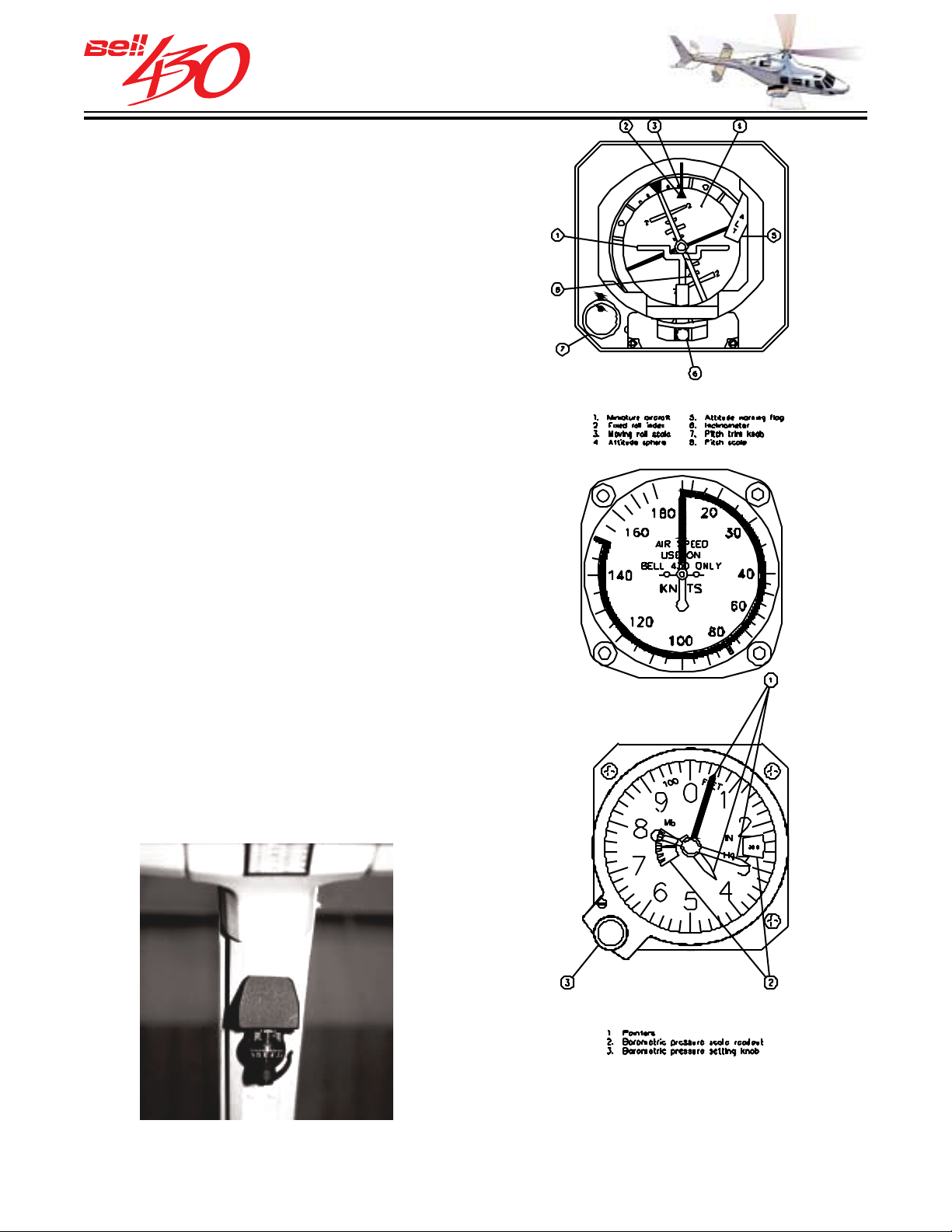
ATTITUDE INDICAT OR
The attitude indicator is a self-contained
4-inch, DC-powered instrument which
displays the pitch and roll flight attitude of
the helicopter in relation to the earth's
horizontal plane. A pitch trim knob adjusts
the aircraft symbol vertically. An
inclinometer is built in to the instrument face
to provide yaw trim indication. An ATT FAIL
flag is visible when attitude information is
unreliable.
AIRSPEED INDICATOR
The airspeed indicator is a standard 3-inch
pitot -static instrument that indicates the
airspeed in knots on a scale graduated from
0 to 180 knots.
ALTIMETER (BAROMETRIC)
The altimeter, a standard 3-inch instrument,
indicates the altitude of the helicopter from
minus 1000 feet to plus 27,500 feet. The
barometric pressure scale for setting
reference pressure is shown in inches of
mercury and in millibars.
STANDBY MAGNETIC COMPASS
The magnetic compass is mounted on the central windshield post. A compass card
holder is provided to record the individual helicopter magnetic deviation.
PRODUCT DATA JANUARY 2003
44
Page 45
THIS ELECTRONIC DOCUMENT MAY HAVE BEEN SUPERCEDED.
THE MOST CURRENT DOCUMENT INFORMATION IS AVAILABLE
THIS IS AN UNCONTROLLED DOCUMENT.
FROM YOUR BELL HELICOPTER TEXTRON REPRESENTATIVE.
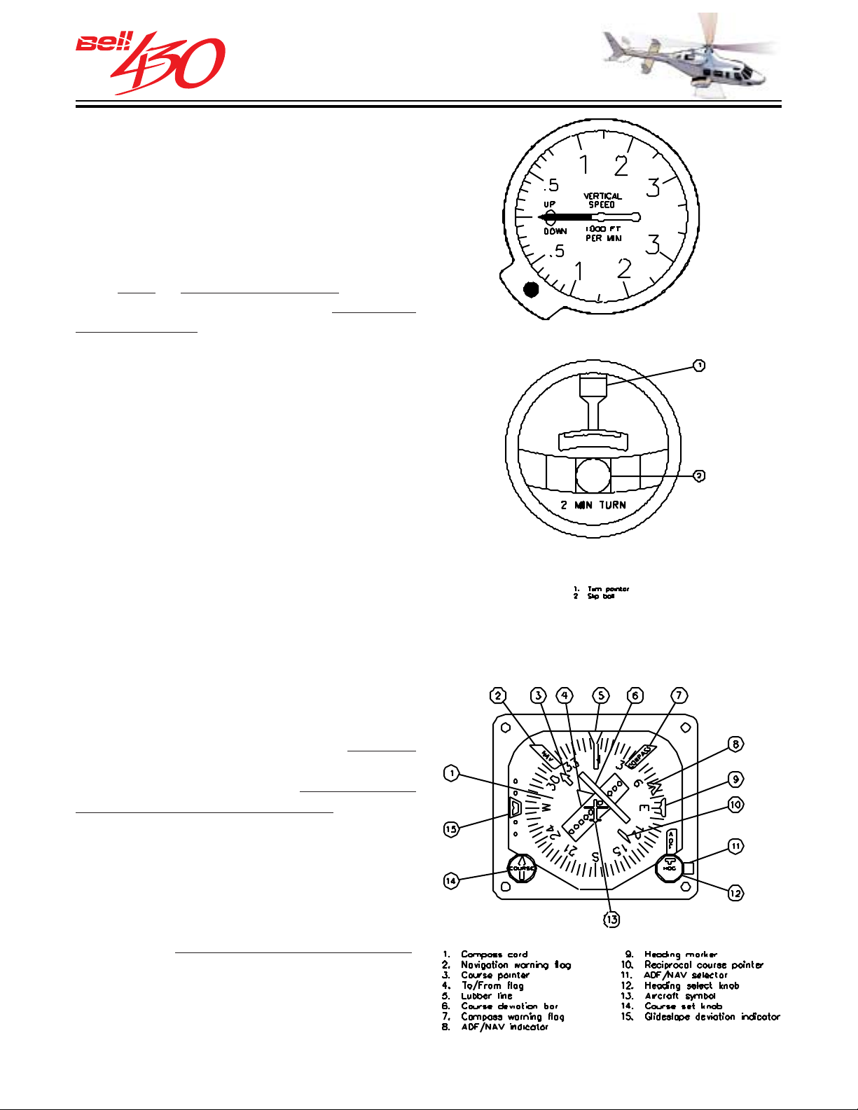
VERTICAL SPEED
The vertical speed indicator is a standard
3-inch instrument which shows the rate of
climb or descent by sensing the rate of
atmospheric pressure change. Information
is shown in feet per minute (fpm) on a scale
zero to plus or minus 3500 fpm. The
from
indicator incorporates a
sensitive
accelerometer to provide instantaneous
vertical speed indication.
TURN & SLIP
The standard 2-inch turn and slip indicator
is a 28 Volt DC powered self contained
gyroscopic instrument which has an
indicating needle to show the rate of turn
of the helicopter, along with fluid dampened
ball which shows turn coordination [trim].
NAVIGATION INDICATORS
HORIZONT AL SITUA TION INDICATOR (HSI)
The HSI provides a display of the gyro
stabilized magnetic heading of the
helicopter. When connected to
VOR / ILS, ADF, and GPS navigation
receivers this instrument
combines the
functions of multiple indicators to display
bearing to / from, selected course, and
course / localizer / glideslope deviation.
The King KPI-552B is driven by the remote
mounted King KCS-305 Gyrocompass
System, located in the aft avionics
compartment. Two adjustment knobs are
used to set
desired heading and course.
Warning flags (NAV, GS, & HDG) appear
to indicate unreliable navigation signal or
gyro failure.
optional
PRODUCT DATA JANUARY 2003
45
Page 46
THIS ELECTRONIC DOCUMENT MAY HAVE BEEN SUPERCEDED.
THE MOST CURRENT DOCUMENT INFORMATION IS AVAILABLE
THIS IS AN UNCONTROLLED DOCUMENT.
FROM YOUR BELL HELICOPTER TEXTRON REPRESENTATIVE.
TOP SECTION
GLARESHIELD MOUNTED CONTROLS
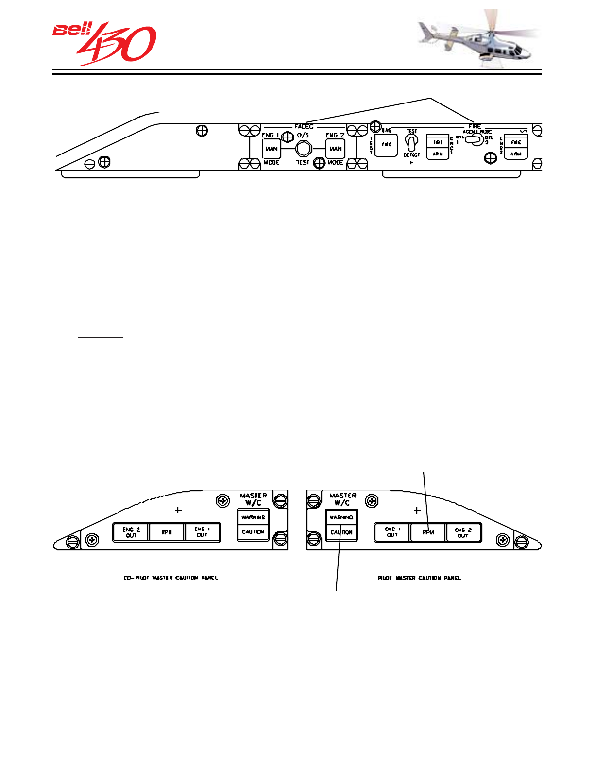
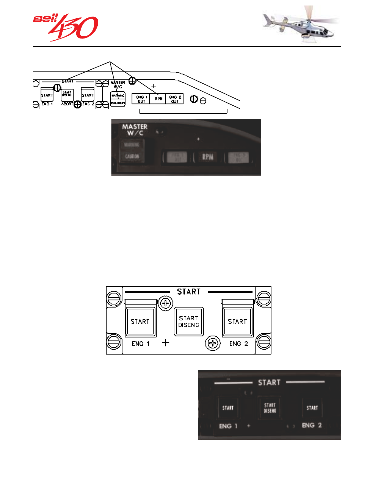
MASTER CA UT ION PANEL [PILO TS ]
The Master Caution Panel is located directly above the pilots' airspeed indicator, and
consists of a split RED warning/ AMBER caution "push to reset" light, and eng 1 out /
RPM /eng 2 out display. When any of the warning/caution annunciators of the IIDS are
activated the
illuminates to alert and direct the pilots' attention to the panel. The press-to-reset feature
extinguishes and rearms the light. The RED ENG OUT lights will illuminate
whenever the respective engines' gas producer speed (NG) drops below 56%±1%.
AMBER MAIN ROTOR RPM caution light will illuminate whenever the main rotor
The
RPM (NR) drops below 93%±1%, or exceeds 105%±1%. In addition to the warning
light, the LOW ROTOR RPM AUDIO is activated when RPM drops below 93%±1%,
transmitting a continuous tone through the intercom system to the pilots' headset. The
tone will continue until rotor RPM is increased above 93%±1%, or the RPM caution
light is pressed.
WARNING or CAUTION (or both) master caution segment light also
OPTIONAL
COPILOT
MASTER W/C
PRESS TO RESET
MASTER W/C
PRESS TO MUTE
RPM AUDIO
RPM AUDIO W ARNING
The RPM audio warning is transmitted through the intercom system and is heard in the
pilot and copilot headsets. The audio warning activates whenever the ROTOR RPM
drops below 93 ±1% (simultaneous with the RPM caution light illumination) and will
continue to sound until the ROTOR RPM is increased above 93 ±1% or ROTOR RPM
drops below 77 ±1%, or the RPM caution light is pressed.
PRODUCT DATA JANUARY 2003
46
Page 47
THIS ELECTRONIC DOCUMENT MAY HAVE BEEN SUPERCEDED.
THE MOST CURRENT DOCUMENT INFORMATION IS AVAILABLE
GLARESHIELD MOUNTED CONTROLS
THIS IS AN UNCONTROLLED DOCUMENT.
FROM YOUR BELL HELICOPTER TEXTRON REPRESENTATIVE.
RPM CAUTION AND WARNING LIGHTS
The RPM caution and warning lights form a cluster with red ENG 1 OUT and ENG 2
OUT warning lights, separated by an amber main rotor RPM caution light. The ENG 1
OUT and ENG 2 OUT lights will illuminate whenever the respective gas producer RPM
(NG) drops below 56%±1%. The main rotor RPM caution light will illuminate whenever
the ROTOR RPM exceeds 105%±1% or droops below 93%±1%. The low ROTOR RPM
will also actuate an audio signal to aid the pilot in distinguishing low RPM condition and
to warn of possible loss of performance. The RPM caution light also incorporates a
press-to-mute feature that silences the audio warning signal.
ENGINE ST ART CONTROL PANEL
Engine starting is controlled by three push
-on illuminated switches mounted above
the engine instruments group. When the
START 1 or START 2 switches are engaged
the AUTOMATIC START SEQUENCE
begins. The starter is continuously
motored until automatic disengagement
occurs at 56%±1% N
DISENG switch is depressed.
or the center START
G
PRODUCT DATA JANUARY 2003
47
Page 48
THIS ELECTRONIC DOCUMENT MAY HAVE BEEN SUPERCEDED.
THE MOST CURRENT DOCUMENT INFORMATION IS AVAILABLE
THIS IS AN UNCONTROLLED DOCUMENT.
FROM YOUR BELL HELICOPTER TEXTRON REPRESENTATIVE.
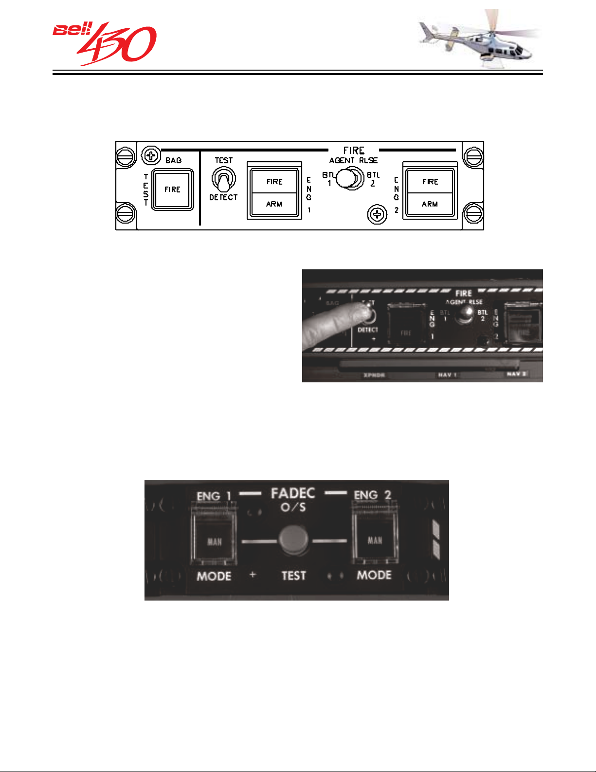
ENGINE / BA GGAGE FIRE PANEL
The engine fire panel is located on the
glareshield, and consists of a RED warning
light / WHITE arm light for each engine
(FIRE ENG 1 & FIRE ENG 2), and a test
switch. The engine fire extinguishing agent
release select switch is located between
the two warning lights. The RED baggage
fire warning light (BAG FIRE) immediately
to the left, is of the press-to-test type.
ENGINE FADEC / OVERSPEED TEST PANEL
The engine FADEC / overspeed test panel consists of guarded push-on switches for
each engine, and a TEST toggle switch located on the glareshield. The MODE switches
control selection of either AUTO or MANUAL mode for the FADEC of each engine. The
toggle switch is used during engine run-up to test the electronic overspeed protection
system of each engine.
PRODUCT DATA JANUARY 2003
48
Page 49
THIS ELECTRONIC DOCUMENT MAY HAVE BEEN SUPERCEDED.
THE MOST CURRENT DOCUMENT INFORMATION IS AVAILABLE
THIS IS AN UNCONTROLLED DOCUMENT.
FROM YOUR BELL HELICOPTER TEXTRON REPRESENTATIVE.
CENTER SECTION
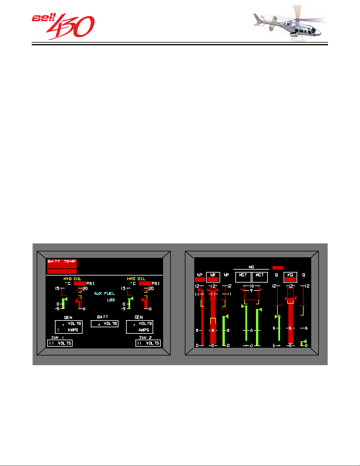
INTEGRA TED INSTRUMENT DISPLAY SYSTEM [ IIDS ]
The Integrated Instrument Display System (llDS) consists of a single integrated color
active matrix liquid crystal display (LCD) unit to display and process the airframe
and engine instrumentation information accurately, and provide caution, warning and
advisory annunciation and controls. The IIDS also performs engine parameter exceedance
monitoring and records these exceedances and faults in nonvolatile memory (NVM)
for maintenance purposes. Warm-up time for the IIDS does not exceed five minutes
after a cold non-operational period at -45°C for ten hours. The IIDS power consumption
does not exceed 120 watts at maximum display brightness not taking into account display
heaters. The displayed data and symbology is crisp and clear and does not have any
smearing effect which would reduce information legibility. The display is consistent
and parameter recognition is easy. Digit and label size is distinct and easy to read to
minimize pilot or crew effort to extract information. The IIDS display is fully readable
under all ambient display illumination as low as 100 ft-lamberts. The display has a
contrast ratio of 10:1 minimum under all possible lighting conditions (day or night) within
viewing angles of 45° ± 5° vertical axis and ±45° horizontal axis. IIDS display colors
are consistent with other flight compartment equipment displays. The colors are white,
red, green, cyan and yellow. Alphanumerics are sized in order to ensure good readability
from both the pilot and copilot positions.
AUTOTRIM EXT PWR
ENG FIRE
1 E/OIL
60 63
ENG2 C/FL
XMSN CHP
800
302
OPEN
28270799
NOTE: DETAILED SYSTEM INFORMATION
BE FOUND IN THE ATTACHED DOCUMENT;
1 FLTR
OVSPD
115
920
28 2
76
54 ALTALT
115
89
OVSPD
99 99
726 649
FOR THE ROGERSON KRATOS IIDS MAY
LINK (RK-IIDS-PHB10-97.PDF)
ECU
91 12
103
PRODUCT DATA JANUARY 2003
49
Page 50
THIS ELECTRONIC DOCUMENT MAY HAVE BEEN SUPERCEDED.
THE MOST CURRENT DOCUMENT INFORMATION IS AVAILABLE
THIS IS AN UNCONTROLLED DOCUMENT.
FROM YOUR BELL HELICOPTER TEXTRON REPRESENTATIVE.
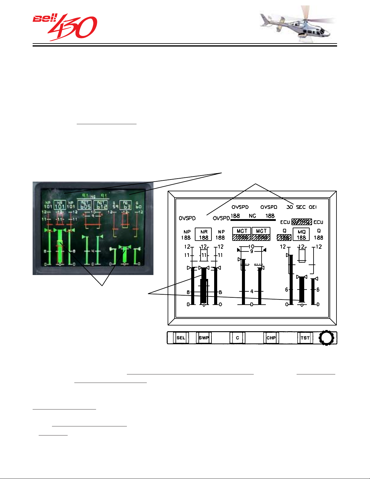
COLOR CODED GRAPHIC & DIGIT AL DA TA
All engine, transmission, hydraulic [temperatures and pressures], and electrical
indications are displayed on the IIDS along with warning, caution, and advisory
messages. Also included is engine and mast torque (Q/MQ), power turbine and
main rotor speed (NP/NR), gas producer speed (NG), and measured gas temperature
(MGT). The electrical systems information shown is voltage and amperage for both
generators, battery voltage, and inverter voltage. Fuel system data displayed is fuel
quantity for
position of the interconnect valve.
both main tanks and total fuel, aux fuel tanks quantity (if installed), and
EXAMPLE INDICATIONS ON PRIMARY DISPLAY PAGE
ALPHANUMERIC
PARAMETER DISPLAYS
VERTICAL SCALE
PARAMETER DISPLAYS
FUNCTION KEYS & BRIGHTNESS
The VERTICAL SCALE displays are color coded to show operating parameters, with
green being used to show
and red for
limit/exceeding limit. All fuel information is displayed blue, except for the
normal/continuous operating range, yellow for cautionary,
last 90 ± 10 pounds (lbs) of fuel which will be displayed red. The DIGITAL information
displays are also color coded; White digits with no background are used to show
normal conditions and values (except NG and AMP where green digits are used), yellow
digits with no background or black digits with a yellow background are used to
show
cautionary conditions, and white digits on a red background are used to announce
a warning.
PRODUCT DATA JANUARY 2003
50
Page 51
THIS ELECTRONIC DOCUMENT MAY HAVE BEEN SUPERCEDED.
THE MOST CURRENT DOCUMENT INFORMATION IS AVAILABLE
THIS IS AN UNCONTROLLED DOCUMENT.
FROM YOUR BELL HELICOPTER TEXTRON REPRESENTATIVE.
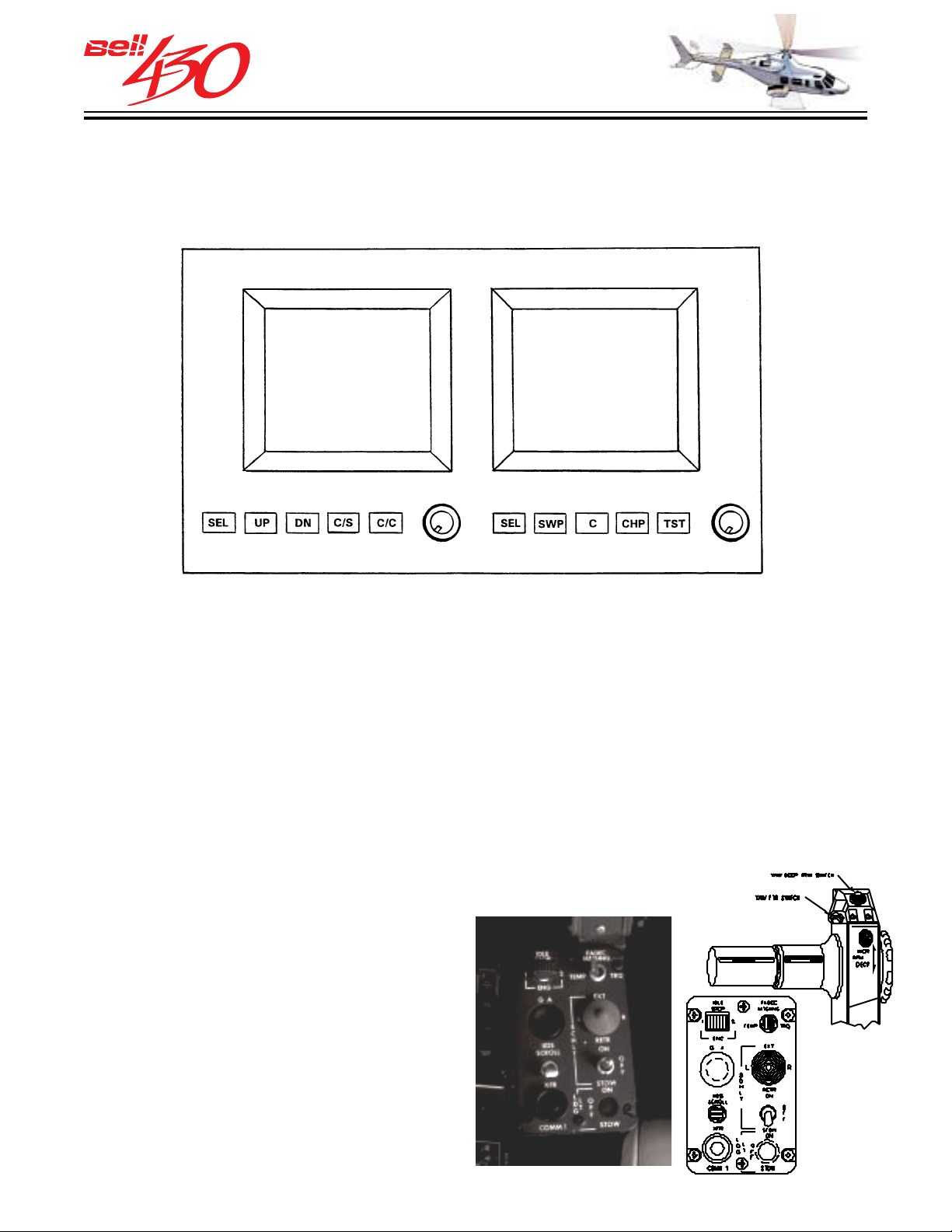
IIDS OPERA TION FEATURES-DISPLAY CONTROLS
The IIDS unit front bezel provides function keys and function identification to allow
flight and ground personnel system interaction. Left and right rotary knobs provide
individual brightness control for each side of the IIDS unit.
LEFT SIDE CONTROLS
1. “SEL” - SELECTS THE VARIOUS
SECONDARY SCREEN FORMATS.
2. “UP” - SCROLLS UP THE WARNING/
CAUTION/ADVISORY WINDOW.
3. “DN” - SCROLLS DOWN THE WARNING/
CAUTION/ADVISORY WINDOW.
4. “C/S” - SELECTS THE CLOCK DISPLAY
MODES.
5. “C/C” - CONTROLS THE CLOCK ET AND
ETD.
PILOT S CROLL CONTROL
In addition to the bezel mounted controls,
the pilot's collective control box has an IIDS
SCROLL button which permits the pilot to
advance through the secondary page
formats without releasing the primary flight
controls.
RIGHT SIDE CONTROLS
6. “SEL” - SELECTS THE VARIOUS
SECONDARY SCREEN FORMATS.
7. “SWP” - SWAPS THE PRIMARY AND
SECONDARY SCREEN
8. “C” - SELECTS THE COMPOSITE
SCREEN FORMATS.
9. “CHP” - TRIGGERS THE CHIP FUZZ
BURNER OUTPUT.
10. “TST” - PILOT INITIATED BIT.
PRODUCT DATA JANUARY 2003
51
Page 52
THIS ELECTRONIC DOCUMENT MAY HAVE BEEN SUPERCEDED.
THE MOST CURRENT DOCUMENT INFORMATION IS AVAILABLE
THIS IS AN UNCONTROLLED DOCUMENT.
FROM YOUR BELL HELICOPTER TEXTRON REPRESENTATIVE.
IIDS OPERATION FEATURES-DUAL POWER & PROCESSORS
The IIDS processes and displays information from the engines and systems separately so that a single failure does not cause the complete loss of one parameter for both engines/systems. The IIDS contains two power supplies, two independent
microprocessors and two independent displays.
Each power supply has two isolated 28 Volt DC inputs from two helicopter sources
so that the loss of one power source does not cause the loss of the alternate power
source or loss of power altogether. Two processors ensure the loss of one processor
does not cause the loss of any information shown on the display, except for fuel quantity,
where loss of one processor will cause the loss of its associated fuel sensor, and only
the fuel in one side of the fuel system will be displayed. In the event of a failure of one
of the displays, pressing the “C” switch under the primary display will cause the composite
screen to be shown.
IIDS OPERA TION FEATURES-DU AL DATA INPUT
The IIDS receives data for most display parameters from dual sources. All operating system data transmitted on the AIRINC 429 data bus is available to the IIDS, as well as
the corresponding analog input port data for each parameter [thermocouple signal,
monopole pulse signal, transducer signal, etc.]. Whenever the primary source of data
for a MGT, Q, NP, NR, or NG parameter is missing or invalid, the secondary source will
provide backup data for display. When data displayed is from a secondary source (except
NG), the word “ALT” will be displayed below the data. If both primary and secondary
sources are missing or invalid the digital display will revert to dashes, the vertical scale
will remain empty, and an amber “FAIL” (except NG) will appear below the scale.
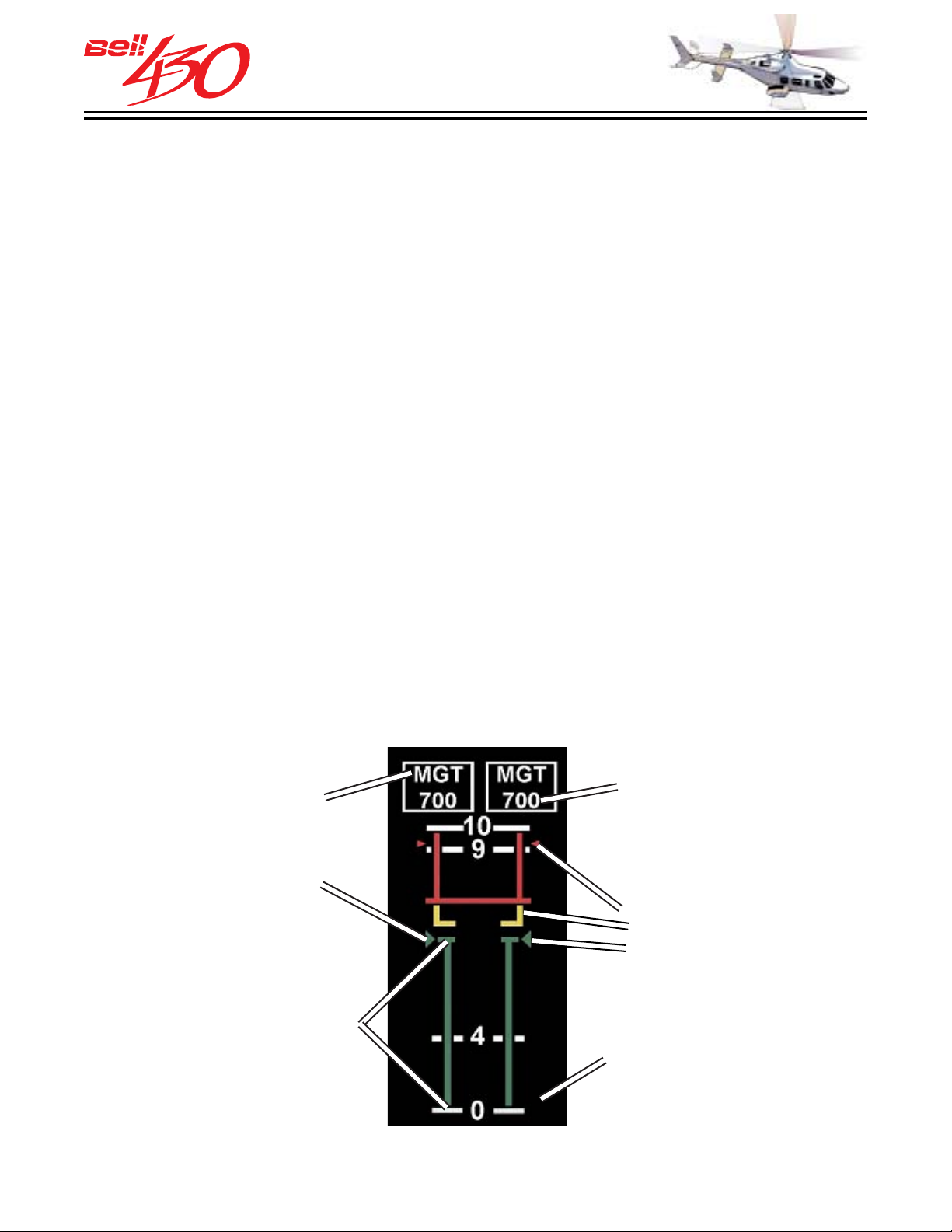
TYPICAL DISPLAY FEA TURES
LABEL
IDENTIFIES
DATA
POINTER
[TRIANGLE]
FOLLOWS RISE
AND FALL OF
VERTICAL SCALE
VERTICAL SCALE
RISES AND FALLS;
CHANGES COLOR
GREEN/YELLOW/RED
FOR CONTINUOUS/
OPER. LIMIT/
MAX. LIMIT
DIGITAL DISPLAY
OF SCALE
INDICATION
TAPE CHANGES
COLORS WHEN
TIME LIMIT PWR
IS REACHED
START LIMIT
TOP[5 MIN]
MCP[CONT.]
ALT OR FAIL
MESSAGE
INDICATE DATA
SOURCE & LOSS
PRODUCT DATA JANUARY 2003
52
Page 53
THIS ELECTRONIC DOCUMENT MAY HAVE BEEN SUPERCEDED.
THE MOST CURRENT DOCUMENT INFORMATION IS AVAILABLE
THIS IS AN UNCONTROLLED DOCUMENT.
FROM YOUR BELL HELICOPTER TEXTRON REPRESENTATIVE.
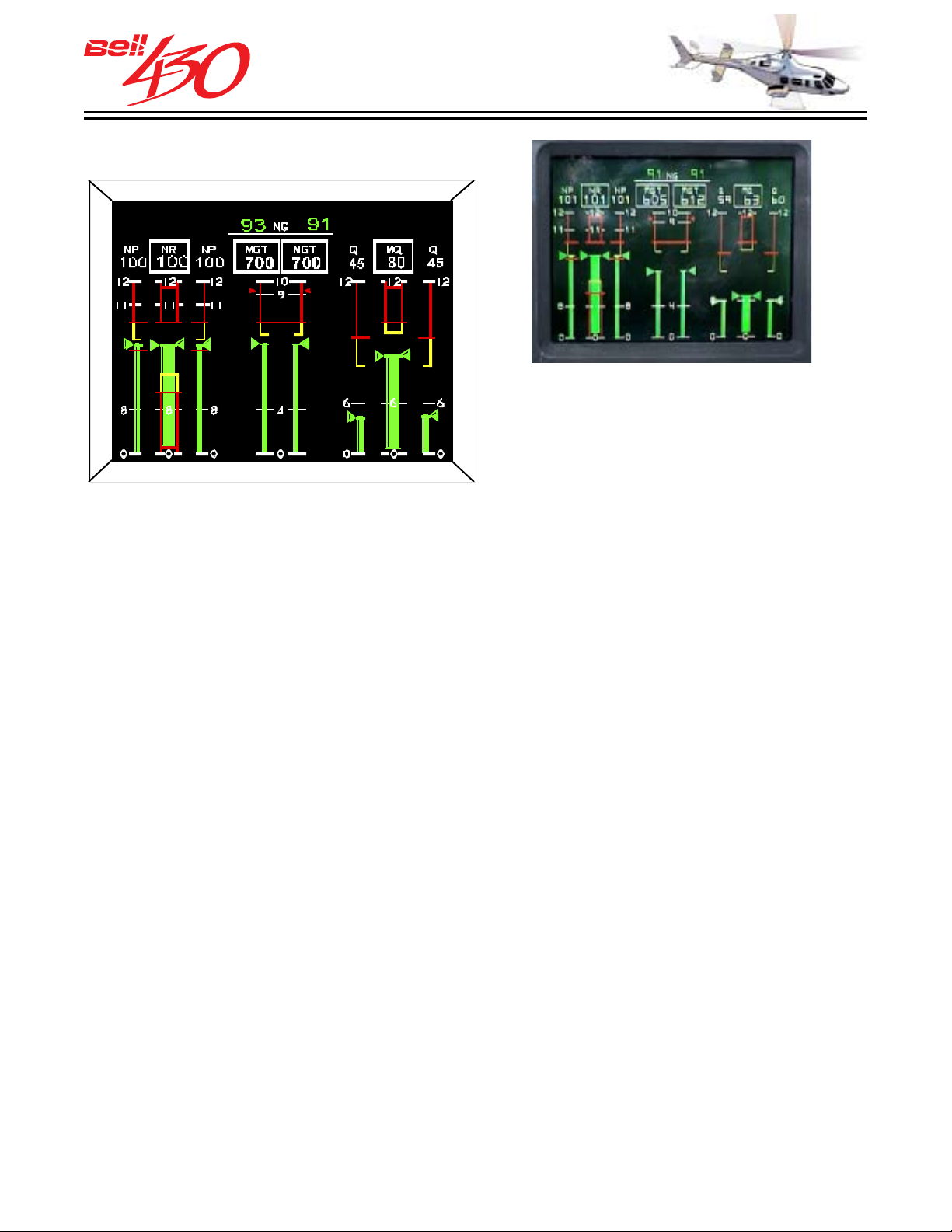
IIDS DISPLA Y PAGE FORMATS
PRIMARY DISPLAY PAG E
WARNING/CAUTION/ADVISORY MESSAGES
The WARNING, CAUTION, and ADVISORY
messages available for all display pages
will be described as a GROUP immediately
following the descriptions of the SYSTEM
data displays.
PRIMARY PAGE DATA
[COLUMNS FROM LEFT TO RIGHT]
1. ENGINE ONE NP
2. ROTOR RPM
3. ENGINE TWO NP
4. ENGINE ONE MGT [W/DIGITAL NO. 1 NG]
5. ENGINE TWO MGT [W/DIGITAL NO. 2 NG]
6. ENGINE ONE TORQUE
7. ROTOR TORQUE
8. ENGINE TWO TORQUE
[DIGITAL INDICATIONS AND ADVISORY TEXT
APPEARS ABOVE THE RESPECTIVE COLUMN]
TRIPLE TA CHOMETER
The triple tachometer display has three
vertical scale displays that simultaneously
display rotor RPM (NR) on the inner scale
and engine 1 and 2 NP on the left and right
scales. Engine and rotor speed data is also
displayed in digital format above the vertical
scales. The data displayed is in percent
of allowable RPM.
MEASURED GAS TEMPERATURE INDICATORS
The measured gas temperature (MGT)
display presents the engine gas
temperature of air between gas producer
turbine and power turbine, in degrees
Celsius. MGT data is displayed on a vertical
scale in the center of the primary screen
and in digital format just above it.
TRIPLE TORQUE DISPLA Y
The triple torque display simultaneously
displays torque output of two engines (Q)
and torque applied to main rotor mast (MQ).
Engine torque is displayed on the right and
left vertical scales, and main rotor mast
torque is displayed on the center vertical
scale. All indications are percent of
maximum torque. Torque data is also
displayed in digital format just above the
vertical scales.
GAS PRODUCER TA CHOMETERS
The gas producer tachometer (NG) display
is presented in digital form only directly
above the MGT display in the middle of the
primary IIDS screen.
PRODUCT DATA JANUARY 2003
53
Page 54
THIS ELECTRONIC DOCUMENT MAY HAVE BEEN SUPERCEDED.
THE MOST CURRENT DOCUMENT INFORMATION IS AVAILABLE
FROM YOUR BELL HELICOPTER TEXTRON REPRESENTATIVE.
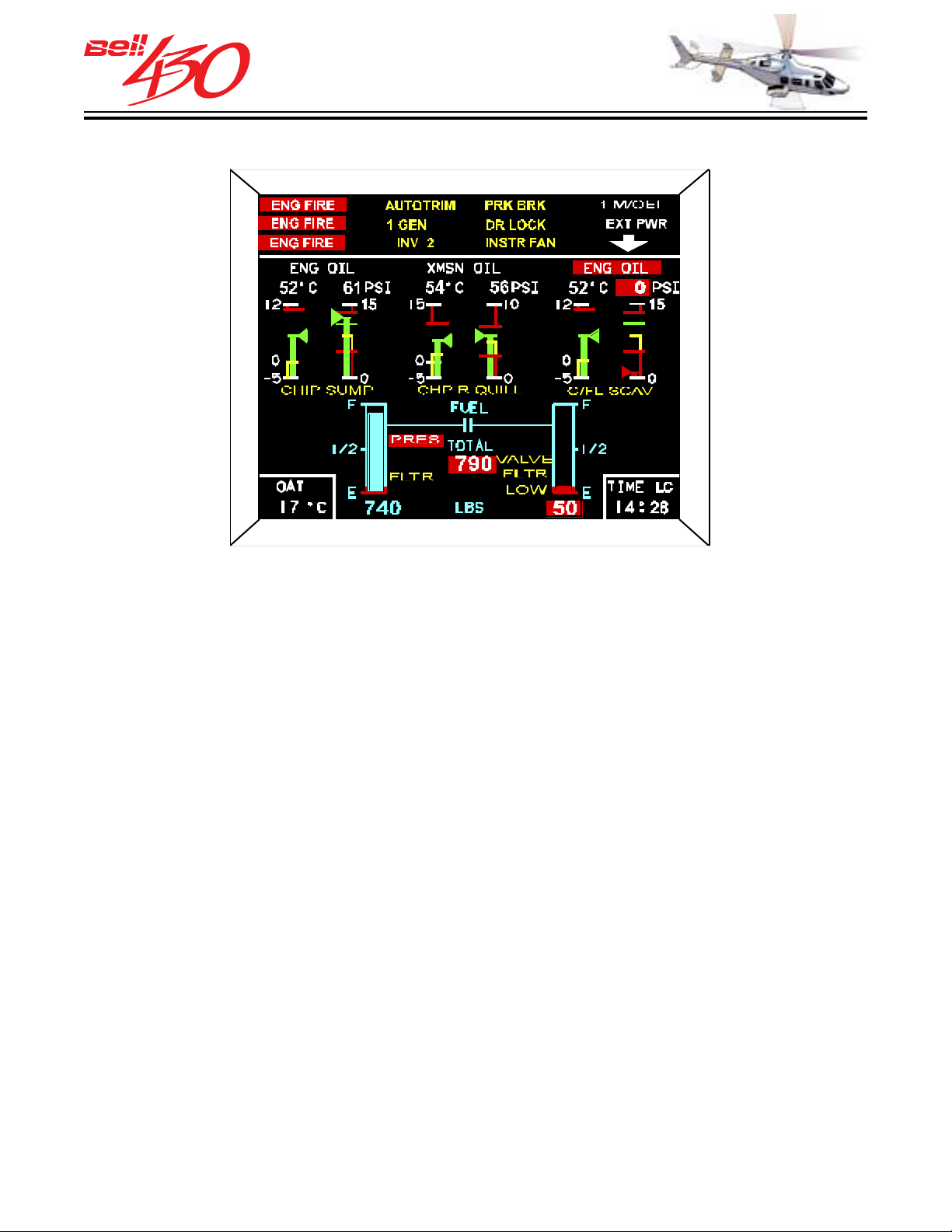
SECONDARY PA GE ONE
THIS IS AN UNCONTROLLED DOCUMENT.
W/C/A MESSAGES
The WARNING, CAUTION, and ADVISORY
messages available for all display pages
will be described as a GROUP immediately
following the descriptions of the SYSTEM
data displays.
ENGINE OIL TEMPERATURE AND
PRESSURE DISPLAYS
Both engine oil temperature and pressure
displays simultaneously present oil
temperature in degrees Celsius on the left
scale and oil pressure in PSI on the right
scale. Temperature and pressure data is
displayed on a vertical scale and in digital
format just above it.
OUTSIDE AIR TEMPERATURE
Outside air temperature (OAT) display is
a digital format display on page 1 and the
START page of the secondary IIDS display.
The OAT temperature probe protrudes from
the underside of the nose. The system
displays OAT within a range of -60 to +105
degrees C.
SECONDARY PAGE ONE DATA
[UPPER DATA BOX]
WARNING CAUTION ANNUNCIATOR DISPLAY
[UPPER DATA ROW-FROM LEFT TO RIGHT]
1. ENGINE ONE OIL TEMPERATURE
2. ENGINE ONE OIL PRESSURE
3. TRANSMISSION OIL TEMPERATURE
4. TRANSMISSION OIL PRESSURE
5. ENGINE TWO OIL TEMPERATURE
6. ENGINE TWO OIL PRESSURE
[LOWER DATA ROW-LEFT TO RIGHT]
1. OUTSIDE AIR TEMPERATURE
2. LH, TOTAL, AND RH FUEL [LBS]
[FUEL FLOW INDICATION OPTIONAL]
3. TIME
TRANSMISSION OIL
TEMPERATURE AND PRESSURE
DISPLAY
The transmission oil temperature and
pressure displays simultaneously present
the oil temperature in degrees Celsius on
the left scale and oil pressure in PSI on the
right scale. Temperature and pressure data
is displayed on a vertical scale and in digital
format just above it.
PRODUCT DATA JANUARY 2003
54
Page 55
THIS ELECTRONIC DOCUMENT MAY HAVE BEEN SUPERCEDED.
THE MOST CURRENT DOCUMENT INFORMATION IS AVAILABLE
FROM YOUR BELL HELICOPTER TEXTRON REPRESENTATIVE.
FUEL QUANTITY DISPLAY
THIS IS AN UNCONTROLLED DOCUMENT.
The fuel quantity display presents left and
right fuel system quantity as individual
vertical scales with a digital total fuel
quantity in between. Advisory text
indications show low fuel pressure, fuel
valve position, fuel filter bypass, and low
fuel warning. The fuel quantity scales are
normally BLUE, with the last 90±10 pounds
shown RED. If the optional fuel flow
indicating system is installed the left and
right fuel flow digital indications will appear
on outboard sides of the fuel quantity
display.
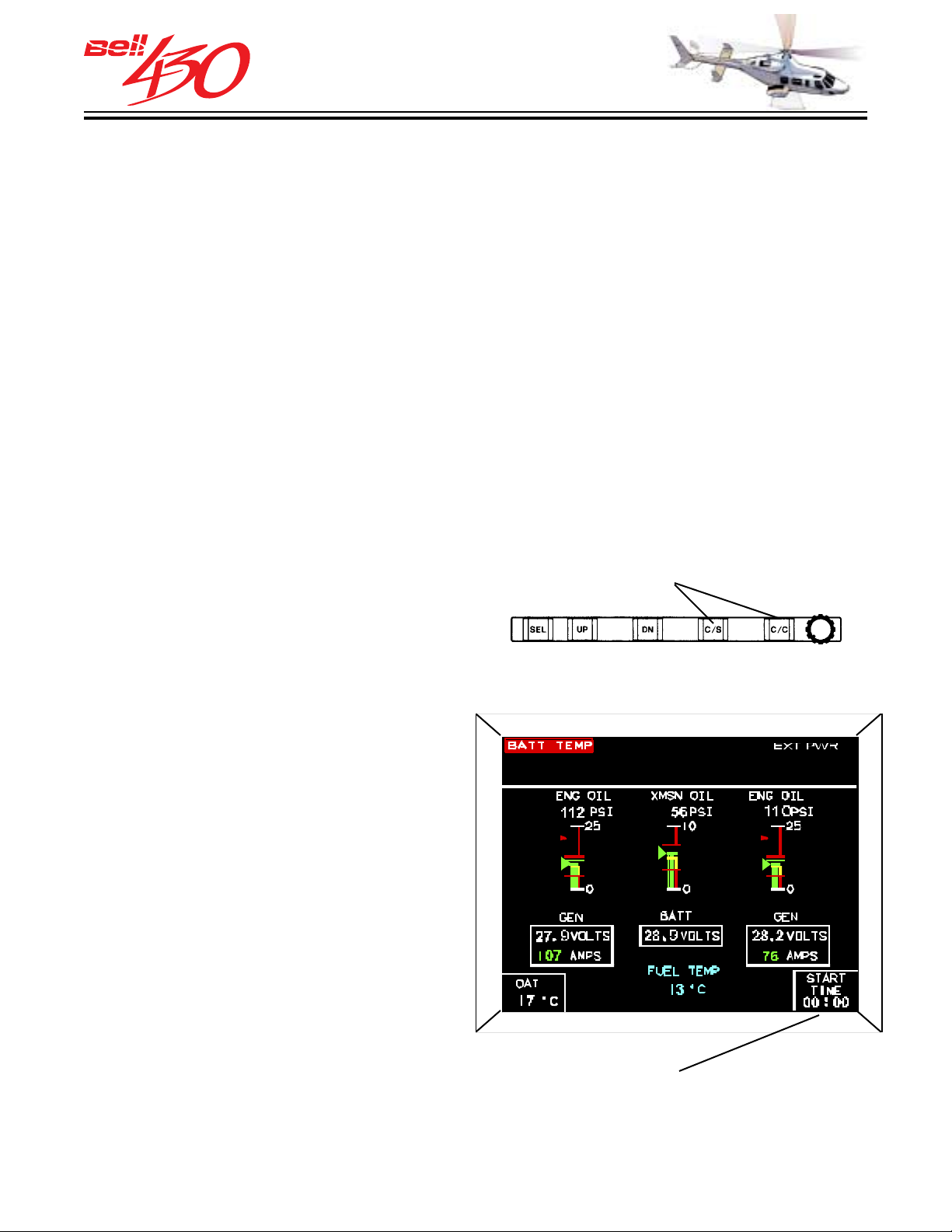
CLOCK
The clock is a digital display in the lower
right corner of the IIDS secondary screen,
page 1. The clock is controlled by two
control buttons under the screen. An
auxiliary rechargeable battery pack [dual,
9 Volt DC nickel-cadmium type] provides
electrical power to keep the clock function
active [but not displayed] whenever normal
28 Volt DC is not available to the IIDS. The
battery pack is recharged anytime normal
electrical power is applied to the airframe.
The clock modes are as follows:
operation, GMT, LC, ET, or ETD. The clock
control (C/C) switch is used to start, stop,
and reset the ET clock, or to set the ETD
counter to the desired value.
The START TIME clock mode is displayed
on the lower right corner of the START
PAGE and is the only clock mode available
during engine start. The start clock
automatically begins counting up from zero
when the first engine throttle is moved for
start. The counter stops upon starter
shutoff, resets to zero and begins counting
again when the second engine throttle is
advanced for start.
CLOCK FUNCTION SOFT-KEYS
SECONDARY PAGE DISPLAY
START PA G E
•Greenwich Mean Time (GMT) in 24 hour
format.
•Local Time (LC) in 24 hour format.
•Elapsed Time (ET) count up timer to
maximum of 99 hours, 59 minutes.
•Elapsed Time (ETD) count down timer from
maximum 59 minutes, 59 seconds.
The clock select (C/S) switch, on the IIDS
bezel, is used to select the mode for
PRODUCT DATA JANUARY 2003
55
START PAGE START TIME CLOCK
Page 56
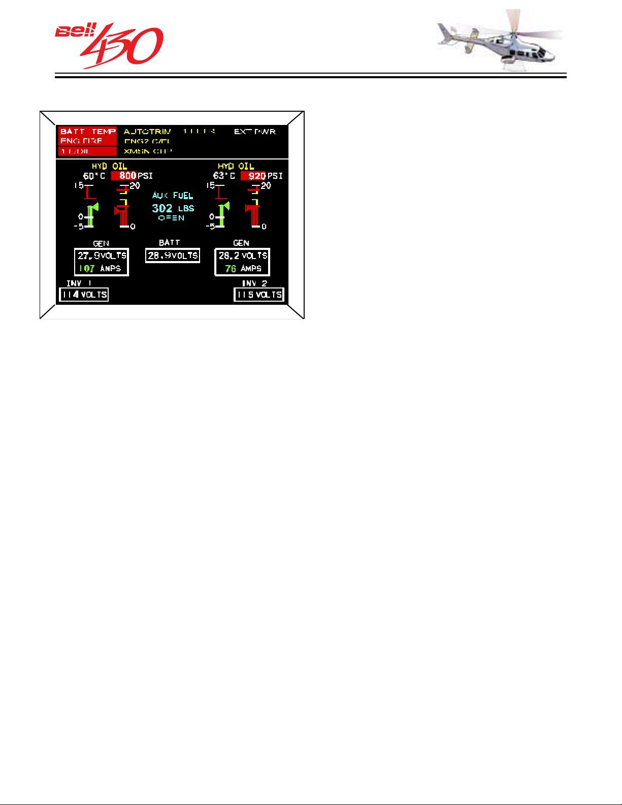
THIS ELECTRONIC DOCUMENT MAY HAVE BEEN SUPERCEDED.
THE MOST CURRENT DOCUMENT INFORMATION IS AVAILABLE
FROM YOUR BELL HELICOPTER TEXTRON REPRESENTATIVE.
SECONDARY PA GE TW O
THIS IS AN UNCONTROLLED DOCUMENT.
SECONDARY PAGE TWO DATA
[UPPER DIGITAL DATA BOX]
WARNING CAUTION ANNUNCIATOR DISPLAY
[UPPER GRAPHIC DATA ROW-LEFT TO RIGHT]
1. NO. 1 HYD OIL TEMPERATURE
2. NO. 1 HYD OIL PRESSURE
3. OPTIONAL AUX FUEL [LBS]
4. NO. 2 HYD OIL TEMPERATURE
5. NO. 2 HYD OIL PRESSURE
[LOWER DIGITAL DATA ROW-LEFT TO RIGHT]
1. NO. 1 GEN VOLTS/AMPS
2. BATTERY VOLTS
3. NO. 2 GEN VOLTS/AMPS
[BOTTOM DIGITAL DATA ROW]
1. INVERTER NO. 1 VOLTS
2. INVERTER NO. 2 VOLTS
WARNING/CAUTION/ADVISORY
MESSAGES
The WARNING, CAUTION, and ADVISORY
messages available for all display pages
will be described as a GROUP immediately
following the descriptions of the SYSTEM
data displays.
HYDRA ULIC TEMPERATURE AND
PRESSURE DISPLAYS
A hydraulic temperature and pressure
display simultaneously presents hydraulic
fluid temperature, in degrees Celsius, on
the left vertical scale and fluid pressure,
in psi, on the right vertical scale for each
system. This data is also presented in digital
format. The displays are connected to
pressure transmitters located on the
pressure manifolds and to temperature
sensing bulbs on the system reservoirs.
AUXILIARY FUEL QUANTITY DISPLAY [OPTIONAL]
AUXILIARY fuel quantity (if installed) is
displayed between the hydraulic system
displays as a digital total. Advisory text
shows the position of the fuel transfer valve
(open/closed/in transit).
BA TTERY VOL T A GE DISPLA Y
Battery voltage is presented in numerical
format on the IIDS secondary screen, page
2 and start page.
GENERA TOR VOL T A GE AND
CURRENT DISPLAY
Each generator voltage and current output
is presented in numerical format on the IIDS
secondary screen, page 2 and start page.
PRODUCT DATA JANUARY 2003
INVERTER VOL TAGE DISPLA Y
Each inverter voltage output is presented
in numerical format on the IIDS secondary
screen, page 2.
56
Page 57
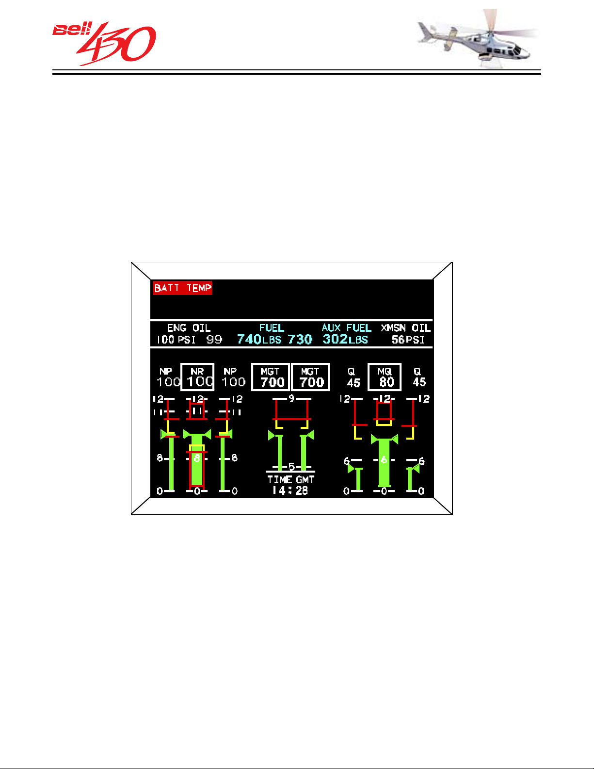
THIS ELECTRONIC DOCUMENT MAY HAVE BEEN SUPERCEDED.
THE MOST CURRENT DOCUMENT INFORMATION IS AVAILABLE
THIS IS AN UNCONTROLLED DOCUMENT.
FROM YOUR BELL HELICOPTER TEXTRON REPRESENTATIVE.
COMPOSITE P AGE
This display page format is provided in the
event one of the dual LCD displays should
fail. The data shown is a condensed
version of that found on the PRIMARY
DISPLAY PAGE , along with Engine Oil
Pressures, Transmission Oil Pressure, Fuel
Quantity (Aux Fuel), and Clock [presented
as digital only indications]
W/C/A MESSAGES
The WARNING, CAUTION, and ADVISORY
messages available for all display pages
will be described as a GROUP immediately
following the descriptions of the SYSTEM
data displays.
COMPOSITE PAGE DATA
[UPPER DATA BOX]
WARNING CAUTION ANNUNCIATOR
DISPLAY
[UPPER DIGITAL DATA ROW-FROM LEFT TO
RIGHT]
1. NO. 1 & NO. 2 ENG OIL PRESS [PSI]
2. LEFT & RIGHT FUEL QTY [LBS]
3. OPTIONAL AUX FUEL [LBS]
4. TRANSMISSION OIL PRESS [PSI]
[LOWER GRAPHIC DATA ROW-LEFT TO RIGHT]
1. ENGINE ONE NP
PRODUCT DATA JANUARY 2003
[BOTTOM DIGITAL DATA ROW]
57
2. ROTOR RPM
3. ENGINE TWO NP
4. ENGINE ONE MGT [W/DIGITAL NO. 1 NG]
5. ENGINE TWO MGT [W/DIGITAL NO. 2 NG]
6. ENGINE ONE TORQUE
7. ROTOR TORQUE
8. ENGINE TWO TORQUE
[DIGITAL INDICATIONS AND ADVISORY
TEXT APPEARS ABOVE THE RESPECTIVE
COLUMN]
1. CLOCK
Page 58
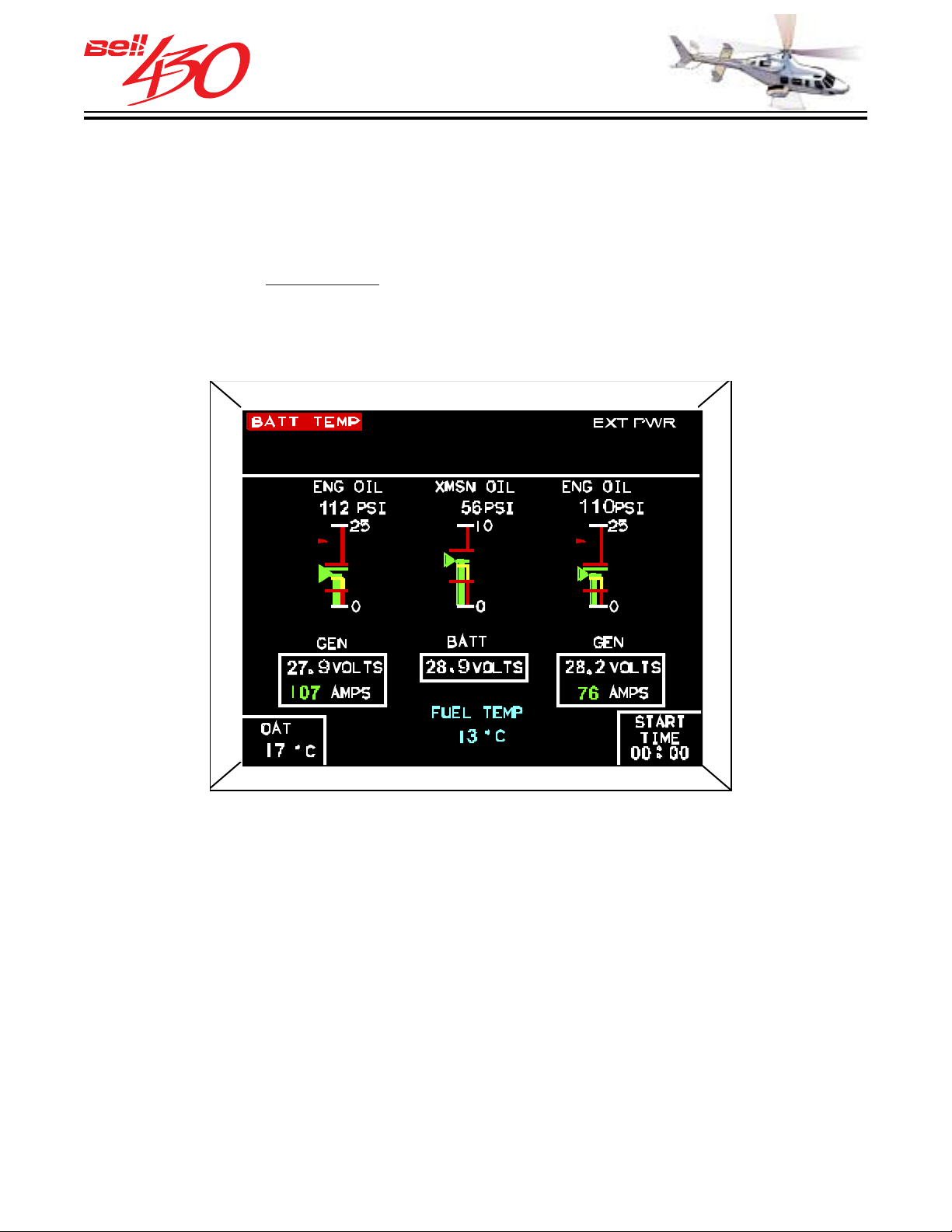
THIS ELECTRONIC DOCUMENT MAY HAVE BEEN SUPERCEDED.
THE MOST CURRENT DOCUMENT INFORMATION IS AVAILABLE
THIS IS AN UNCONTROLLED DOCUMENT.
FROM YOUR BELL HELICOPTER TEXTRON REPRESENTATIVE.
START P A GE FORMAT
When performing an engine start sequence,
the secondary page display may be scrolled
to the START PAGE, which presents
expanded scale representations of engine
and transmission
engines are running (both engines NG
above 10% indicated) access to this page
is inhibited.
oil pressure . If both
FUEL TEMPERATURE DISPLAY
The fuel temperature display is a digital
readout which displays the fuel temperature
from the tank in degrees Celsius. This
display is provided on the bottom center
area of the start page. The display range
is from -50 to 100 C. The display is driven
by a temperature bulb located at the bottom
of the fuel tank.
START PAGE DATA
[UPPER DIGITAL DATA BOX]
WARNING CAUTION ANNUNCIATOR DISPLAY
[UPPER GRAPHIC DATA ROW-LEFT TO RIGHT]
1. NO. 1 ENG OIL PRESS
2. TRANSMISSION OIL PRESSURE
3. NO. 2 ENG OIL PRESS
[DIGITAL INDICATIONS AND ADVISORY TEXT
APPEARS ABOVE THE RESPECTIVE
COLUMN]
[LOWER DIGITAL DATA ROW-LEFT TO RIGHT]
1. NO. 1 GEN VOLTS/AMPS
2. BATTERY VOLTS
3. NO. 2 GEN VOLTS/AMPS
[BOTTOM DIGITAL DATA ROW]
1. OUTSIDE AIR TEMPERATURE
2. FUEL TEMPERATURE
3. START TIMER
PRODUCT DATA JANUARY 2003
58
Page 59
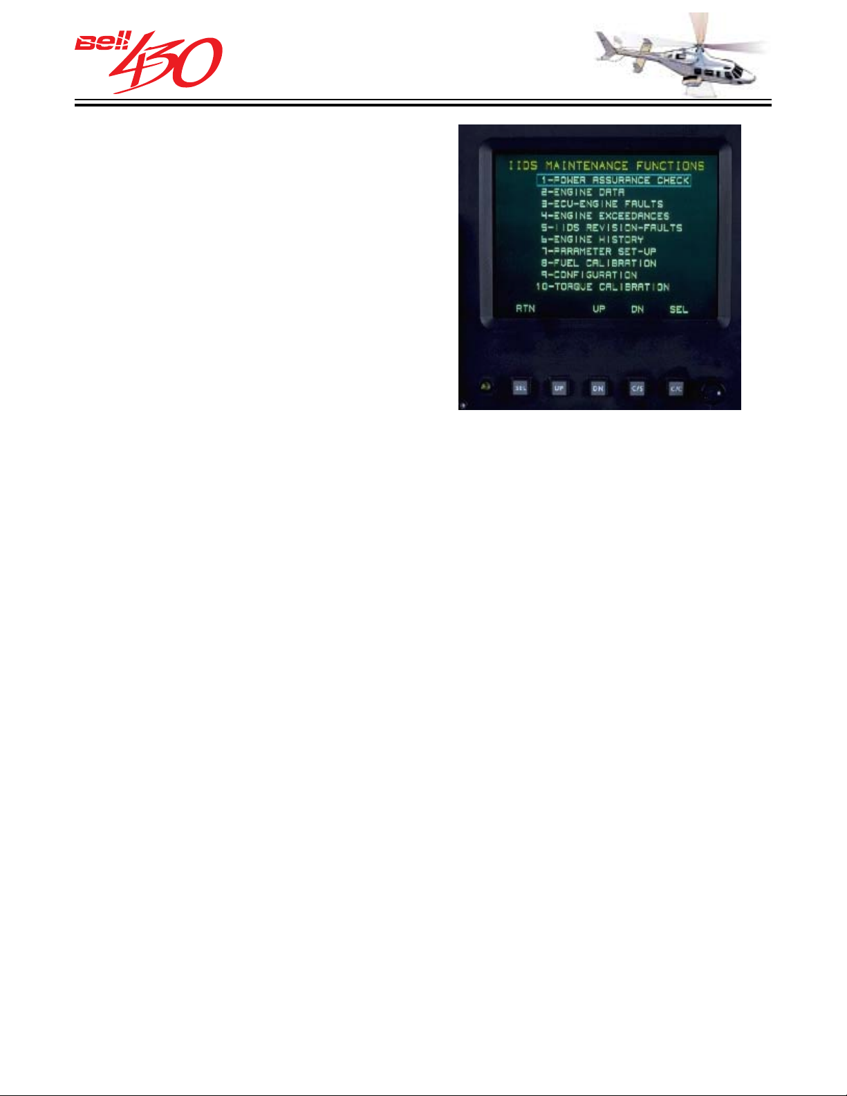
THIS ELECTRONIC DOCUMENT MAY HAVE BEEN SUPERCEDED.
THE MOST CURRENT DOCUMENT INFORMATION IS AVAILABLE
THIS IS AN UNCONTROLLED DOCUMENT.
FROM YOUR BELL HELICOPTER TEXTRON REPRESENTATIVE.
MAINTENANCE PAGES
The maintenance pages are accessed by
simultaneously pressing the two outboard
soft-key bezel switches under either IIDS
screen, SEL and TST switches on the
secondary screen, or SEL and C/C switches
on the primary screen. This will display the
IIDS MAINTENANCE FUNCTIONS page.
After entrance to the Top Level
Maintenance Page, the functions of the softkeys below each screen will be changed
to the function specified above each key
at the bottom edge of the LCD display. Using
the UP, DN, and SEL switches will allow
the selection of the desired maintenance
function, while RTN will exit the display to
its' normal display format. Each of the
maintenance function displays are MENU
DRIVEN, with various soft-key functions
specified above each key at the bottom
edge of the LCD display.
TOP LEVEL MAINTENANCE DISPLAY
ENGINE HOURMETER
The engine hourmeter is an integral part
of the IIDS and can be accessed thorough
the ENGINE HISTORY maintenance pages.
There are ten maintenance functions accessible through the IIDS. They are;
1. POWER ASSURANCE CHECK
2. ENGINE DATA
3. ECU-ENGINE FAULTS
4. ENGINE EXCEEDANCE
5. IIDS REVISION-FAULTS
6. ENGINE HISTORY [HOURMETER]
7. PARAMETER SETUP
8. FUEL CALIBRATION
9 CONFIGURATION
10. MAST TORQUE CALIBRATION
PRODUCT DATA JANUARY 2003
59
Page 60
THIS ELECTRONIC DOCUMENT MAY HAVE BEEN SUPERCEDED.
THE MOST CURRENT DOCUMENT INFORMATION IS AVAILABLE
THIS IS AN UNCONTROLLED DOCUMENT.
FROM YOUR BELL HELICOPTER TEXTRON REPRESENTATIVE.
WARNING / CAUTION SYSTEM
The Warning/Caution System includes all warning, caution, and advisory lights related
to the numerous helicopter systems as well as the electrical power and sensors required
to operate them. With the introduction of the IIDS, the old style separate caution panel
has been eliminated. The IIDS now displays all previously available warning and caution
indications, provides numerous additional caution, warning, and advisory indications
previously not available. The older style master caution lights have been replaced with
new master w/c lights. Specific IIDS warning, caution and advisory indications, as well
as instrument panel and glareshield panel mounted ENGINE OUT warnings RPM caution,
FADEC, FIRE, and START indications are covered in detail in the areas relating to
those systems.
W ARNING/CAUTION/AD VISOR Y WINDOW
The upper portion of Display 1 incorporates the WARNING / CAUTION/ADVISORY
WINDOW. It is commonly referred to as the W/C/A Window and consists of the three
lines, each of which is divided horizontally into four segments. Each of the twelve (12)
segments can display either a warning, caution or advisory message.
A warning message consists of
black letters on an amber background and an advisory message will consist of
has
white lettering on a black background.
white lettering on a red background, a caution message
Should there be more than 12 messages active at one time, an arrow, pointing either
upwards or downwards will appear in one of the segments in the far right column of
messages. The arrow indicates that the pilot should scroll the Display 1 pages up or
down, depending on how the arrow is pointing to see more messages.
WARNING / CAUTION / ADVISORY INDI CATI ONS
[ DISPLAY S IN THE IIDS W / C / A WINDO W ]
RED AMBER WHITE
AFCS DI SC * AF CS PIT* ENG 2 C/ FL LDG G R UP* A/FUEL OP*
BAG FIRE AFCS ROL* CDPU FL P AGE 2 A/FUEL XT*
BATT TEMP AFCS YAW* D R LOCK PARK BRK* 1 A/IC E 2
ENG FIRE AP* FAIL RPM C/H ARM*
1 E/OIL 2 A/RLT 1 GEN 2 SCAS* EXT PWR
1 FU/ PR 2 AUTOTRIM* 1 HYD 2 SRT ABT FLTS ARM*
1 GEN 2** BATT RLY 1 FLTR 2 1 VA LVE 2 FUEL INT
RTR BRK BUS INT 1 F/LOW 2 L W/S HOT START
XMSN OIL ENG 1 CHP IIDS R W/S HOT
ENG 2 CHP INST FAN XMSN CHIP
E NG 1 C/FL 1 INV 2 XMSN C/FL
* DISPLAY FOR OPTIONAL EQUIPMENT
** RED WHEN BOTH GEN FAIL
PRODUCT DATA JANUARY 2003
60
Page 61
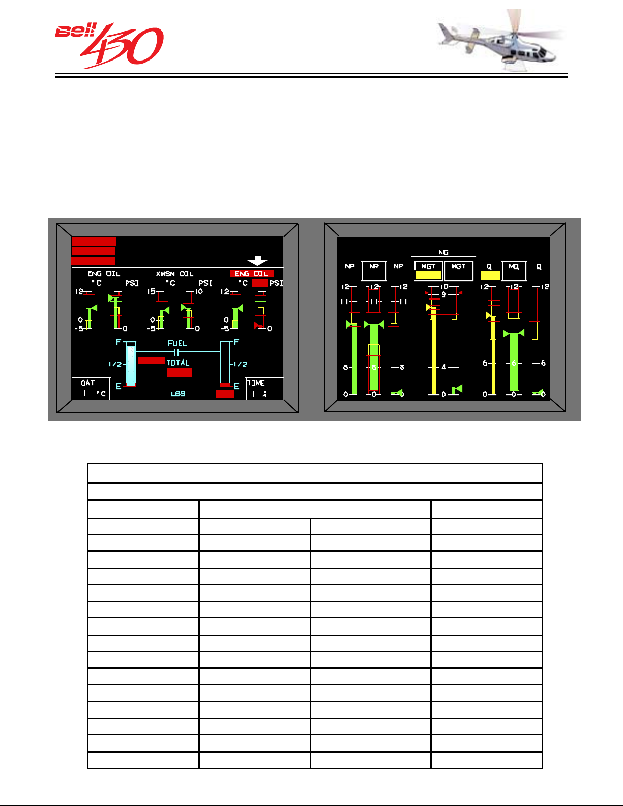
THIS ELECTRONIC DOCUMENT MAY HAVE BEEN SUPERCEDED.
THE MOST CURRENT DOCUMENT INFORMATION IS AVAILABLE
THIS IS AN UNCONTROLLED DOCUMENT.
FROM YOUR BELL HELICOPTER TEXTRON REPRESENTATIVE.
SYSTEM AREA WARNING/CAUTION/ADVISORY INDICATIONS
Additional warning, caution, and advisory messages are embedded within the SYSTEM
AREA of the IIDS displays. In most cases the message will be located in or near the
label of the effected system. The system area embedded messages are primarily related
to the Chip Detection System and the FADEC (faults, failures, overspeed, and OEI
conditions), but also include some messages duplicating or supplementing the messages
in the warning caution window.
ADDITIONAL W/C MESSAGE ARROWWARNING/CAUTION WINDOW
52
C/FL SCAVCHP R QUILL
1 M/OEI
EXT PWR
0
4287
LC
I00 0
I00
99 0
803
ENG FIREENG FIRE
ENG FIRE
ENG FIRE
52
CHIP SUMP
AUTOTRIM
1 GEN
INV 2
61
15 15
PRES
FLTR
54
790
PRK BRK
DR LOCK
INSTR FAN
56
VALVE
FLTR
LOW
740 50
SYSTEM AREA W/C MESSAGES [TYPICAL]
WARNING / CAUTION / ADVISORY INDICATI ONS
[ DISPLAYS IN THE I IDS SYSTEMS A REA ]
RED AMBER WHITE
ECU A/RLT 30SEC OEI OPEN (aux fuel)
PRES (fuel) BUS INT SRT ABT TRANSI T
FAIL (volt/amps) CHIP SUMP VALVE ALT
O/TRQ CHI P SCAV CHIP BRG ECU
XMSN OIL C/FL SUM P CHIP L/R QUILL dash line(f uel int)
C/FL SCAV CHIP TAIL RTR 1 M/ECU 2
FAIL CHIP COLL GEAR 1 M/OEI 2
GEN CHIP PLTRY GEAR
HYD OIL CHIP SUMP PUMP
F L TR C/FL B R G
LOW QTY C/ FL L/R QUI LL
FAIL (IIDS) C/FL TAIL RTR
INV C/FL COLL GEAR
2 MIN OEI C/FL PLTRY GEAR
OVSPD C/ FL SUMP P U MP
120
2 MIN OEI
80
98
0
PRODUCT DATA JANUARY 2003
61
Page 62

THIS ELECTRONIC DOCUMENT MAY HAVE BEEN SUPERCEDED.
THE MOST CURRENT DOCUMENT INFORMATION IS AVAILABLE
THIS IS AN UNCONTROLLED DOCUMENT.
FROM YOUR BELL HELICOPTER TEXTRON REPRESENTATIVE.
WARNING/CAUTION AND ADVISORY INDICATIONS
Messages preceded by 1 indicate fault/condition is in left hand system or No.1 engine;
Messages followed by 2 indicate fault/condition is in right hand system or No.2 engine.
“XMSN OIL”
This warning appears when the
transmission oil pressure increases to 38
psig, decreases to 30±2 psig or the
temperature increases to 110 C. This
warning uses the transmission pressure/
temperature label annunciator by turning
it red and flashing.
“ENG OIL” or “1 E/OIL” (Engine1)
This warning appears when the engine 1
oil pressure decreases below 52.5±2.5
psig. This warning uses the engine 1
pressure/temperature label annunciator by
turning it red and flashing or as “1E/OIL”
in the W/C/A window when on page 2.
“ENG OIL” or “E/OIL 2” (Engine2)
This warning appears when the engine 2
oil pressure decreases below 52.5±2.5
psig. This warning uses the engine 2 oil
pressure/temperature label annunciator by
turning it red and flashing or as “E/OIL 2”
in the W/C/A window when on page 2.
“PRES” or “1 FU/PR” (Engine 1)
This warning appears when the engine 1
fuel pressure decreases below 4.5±1.5
psig. The “PRES” warning appears on the
right hand side of the LH fuel quantity
vertical display when on the secondary
display page 1 or as “1 FU/PR” in the W/C/
A window when on page 2 or the start page.
“RTR BRK”
This warning appears when either or both
of the rotor brake switches are engaged.
This warning appears only into the W/C/S
window.
“BATT TEMP”
This warning appears when the battery
temperature sensor exceeds 71±3°C
(160±5°F). This warning appears only into
the W/C/A window.
“ECU” (Engine 1)
This caution appears when the engine 1
FADEC-ECU sends its failed discrete
output. This output is enabled whenever
sensor or functional faults are detected
such as:
1. Power input fault (dual)
2. CPU fault
3. Speed sensor fault (dual)
4. Memory fault
5. Fuel flow sensor fault
6. PLA fault
This caution appears above the engine 1
torque display on the primary screen.
“ECU” (Engine 2)
“PRES” or “FU/PR 2” (Engine 2)
This warning appears when the engine 2
fuel pressure decreases below 4.5±1.5
psig. The “PRES” warning appears on the
left hand side of the RH fuel quantity vertical
This caution appears when the engine 2
FADEC-ECU sends it failed discrete output.
This output is enabled whenever sensor
or functional faults are detected such as:
1. Power input fault (dual)
display when on the secondary display page
1 or as “FU/PR 2” in the W/C/A window when
2. CPU fault
on page 2 or the start page.
PRODUCT DATA JANUARY 2003
62
Page 63
THIS ELECTRONIC DOCUMENT MAY HAVE BEEN SUPERCEDED.
THE MOST CURRENT DOCUMENT INFORMATION IS AVAILABLE
THIS IS AN UNCONTROLLED DOCUMENT.
FROM YOUR BELL HELICOPTER TEXTRON REPRESENTATIVE.
3. Speed sensor fault (dual)
4. Memory fault
5. Fuel flow sensor fault
6. PLA fault
This caution appears above the engine 2
torque display on the primary screen.
“SCAS”
This warning appears when the AFCS
failure is declared by the FCC. This warning
appears only into the W/C/S window.
“AP”
This warning appears when all the AFCS
trim actuators are failed. This warning
appears only into the W/C/A window.
“AFCS PIT”
This warning appears when the AFCS pitch
trim actuator has failed. This warning
appears only into the W/C/S window.
“AFCS ROL”
This warning appears when the AFCS roll
trim actuator has failed. This warning
appears only into the W/C/A window.
“AUTO TRIM”
This caution appears upon AFCS mistrim
command. This caution appears only into
the W/C/A window.
“INV 1” or “1 INV”
This caution appears when either inverter
1 has failed or 28vdc to the inverter 1 is
not present. This caution actually uses the
inverter 1 voltmeter label as annunciator
by turning it amber and flashing or as “1
INV” in the W/C/A window when on page 1
or the start page.
“INV 2” or “2 INV ”
This caution appears when either inverter
2 has failed or 28vdc to inverter 2 is not
present. This caution actually uses the
inverter 2 voltmeter label as the annunciator
by turning it amber and flashing or as “INV
2” in the W/C/A window when on page 1 or
on the start page.
“DR LOCK”
This caution appears unless all passenger
and baggage compartment doors are
locked. This caution appears only into the
W/C/A window.
“AFCS YAW”
This warning appears when the AFCS yaw
trim actuator has failed. This warning
appears only into the W/C/S window.
“BATT RLY”
This caution appears when the battery relay
in not closed. This caution appears only
into the W/C/A window.
“AFCS DISC”
This warning appears when the AFCS has
disengaged from the aircraft controls. This
warning appears only into the W/C/A
window.
“O/TRQ
This warning appear when the mast torque
has exceeded 100%. This annunciator
remains latched until reset through the
attention-getter. This warning appears
above the mast torque display on the
primary screen.
PRODUCT DATA JANUARY 2003
“1 A/ICE”
This white advisory appears when the
engine 1 anti-ice system is turned on. This
advisory appears only into the W/C/A
window.
“A/ICE 2”
This white advisory appears when the
engine 2 anti-ice system is turned on. This
advisory appears only into the W/C/A
window.
63
Page 64

THIS ELECTRONIC DOCUMENT MAY HAVE BEEN SUPERCEDED.
THE MOST CURRENT DOCUMENT INFORMATION IS AVAILABLE
THIS IS AN UNCONTROLLED DOCUMENT.
FROM YOUR BELL HELICOPTER TEXTRON REPRESENTATIVE.
“CHP SCA V” or “ENG 1 CHP”
(Engine 1)
This caution appears when a chip detection
event has been monitored by the engine
detector in the engine 1 oil outlet connection
and the CDPU. This caution appears below
the engine 1 oil temp/pressure vertical
display or as “ENG 1 CHP” in the W/C/A
window when on the secondary screen page
2.
“CHP SCA V” or “ENG 2 CHP”
(Engine 2)
This caution appears when a chip detection
event has been monitored by the engine
chip detector in the engine 2 oil outlet
connection and the CDPU. This caution
appears below the engine 2 oil temp/
pressure vertical display or as “ENG 2 CHP”
in the W/C/A window when on the secondary
screen page 2.
“CHP SUMP” or “ENG 1 CHP”
(Engine 1)
pressure vertical display or as “ENG 2 CHP”
in the W/C/A window when on the secondary
screen page 2.
“CHIP MAST BRG” or “XMSN CHP”
This caution appears when a chip detection
event has been monitored by the
transmission chip detector in the
transmission assembly, and the CDPU.
This caution appears below the xmsn oil
temp/pressure vertical display or as “XMSN
CHP” in the W/C/A window when on the
secondary screen page 2.
“CHP L Q UILL” or “XMSN CHP”
This caution appears when a chip detection
event has been monitored by the
transmission chip detector in the
transmission assembly, and the CDPU.
This caution appears below the xmsn oil
temp/pressure vertical display or as “XMSN
CHP” in the W/C/A window when on the
secondary screen page 2.
“CHP R QUILL” or “XMSN CHP”
This caution appears when a chip detection
event has been monitored by the engine
chip detector in the engine 1 sump gearbox
assembly and the CDPU. This caution
appears below the engine 1 oil temp/
pressure vertical display or as “ENG 1 CHP”
in the W/C/A window when on the secondary
screen page 2.
“CHP SUMP” or “ENG 2 CHP”
(Engine 2)
This caution appears when a chip detection
event has been monitored by the engine
chip detector in the engine 2 sump gearbox
assembly and the CDPU. This caution
appears below the engine 2 oil temp/
This caution appears when a chip detection
event has been monitored by the
transmission chip detector in the
transmission assembly, and the CDPU.
This caution appears below the xmsn oil
temp/presssure vertical display or as
“XMSN CHP” in the W/C/A window when
on the secondary screen page 2.
“CHP COLL GR” or “XMSN CHP”
This caution appears when a chip detection
event has been monitored by the
transmission chip detector in the
transmission assembly, and the CDPU.
This caution appears below the xmsn oil
temp/pressure vertical display or as “XMSN
CHP” in the W/C/A window when on the
secondary screen page 2.
PRODUCT DATA JANUARY 2003
64
Page 65

THIS ELECTRONIC DOCUMENT MAY HAVE BEEN SUPERCEDED.
THE MOST CURRENT DOCUMENT INFORMATION IS AVAILABLE
THIS IS AN UNCONTROLLED DOCUMENT.
FROM YOUR BELL HELICOPTER TEXTRON REPRESENTATIVE.
“CHP PL TRY GR” “XMSN CHP”
This caution appears when a chip detection
event has been monitored by the
transmission chip detector in the
transmission assembly, and the CDPU.
This caution appears below the xmsn oil
temp/pressure vertical display or as “XMSN
CHP” in the W/C/A window when on
secondary screen page 2.
“CHP SUMP PMP” or “XMSN CHP”
This caution appears when a chip detection
event has been monitored by the
transmission chip detector in the
transmission assembly, and the CDPU.
This caution appears below the xmsn oil
temp/pressure vertical display or as “XMSN
CHP” in the W/C/A window when on the
secondary screen page .
“C/FL SCA V” or “ENG 2 C/FL”
(Engine 2)
This caution appears when a chip detection
failure has been monitored by the CDPU
in engine 2 oil outlet connection chip
detection circuit. This caution appears
below the engine 2 oil temp/pressure
vertical display or as “ENG 2 C/FL” in the
W/C/A window when on the secondary
screen page 2.
“C/FL SUMP” or “ENG 1 C/FL”
(Engine 1)
This caution appears when a chip detection
failure has been monitored by the CDPU
in engine 1 gear box chip detection circuit.
This caution appears below the engine 1
oil temp/pressure vertical display or as
“ENG 1 C/FL” in the W/C/A window when
on the secondary screen page 2.
“CHP TAIL RTR” or “XMSN CHP”
This caution appears when a chip detection
event has been monitored by the tail rotor
chip detector in the tail rotor gear box
assembly, and the CDPU. This caution
appears below the xmsn oil temp/pressure
vertical display or as “XMSN CHP” in the
W/C/A window when on the secondary
screen page 2.
“C/FL SCA V” or “ENG 1 C/FL”
(Engine 1)
This caution appears when a chip detection
failure has been monitored by the CDPU
in engine 1 oil outlet connection chip
detector circuit. This caution appears below
the engine 1 oil temp/pressure vertical
display or as “ENG 1 C/FL” in the W/C/A
window when on the secondary screen page
2.
“C/FL SUMP” or “ENG 2 C/FL”
(Engine 2)
This caution appears when a chip detection
failure has been monitored by the CDPU
in engine 2 gear box chip detection circuit.
This caution appears below the engine 2
oil temp/pressure vertical display or as
“ENG 2 C/FL” in the W/C/A window when
on the secondary screen page 2.
“C/FL MAST BRG” or “XMSN C/FL ”
This caution appears when a chip detection
failure has been monitored by the CDPU
in the transmission mast bearing chip
detection circuit. This caution appears
below the xmsn oil temp/pressure vertical
display or as “XMSN C/FL” in the W/C/A
window when on the secondary screen page
2.
PRODUCT DATA JANUARY 2003
65
Page 66

THIS ELECTRONIC DOCUMENT MAY HAVE BEEN SUPERCEDED.
THE MOST CURRENT DOCUMENT INFORMATION IS AVAILABLE
THIS IS AN UNCONTROLLED DOCUMENT.
FROM YOUR BELL HELICOPTER TEXTRON REPRESENTATIVE.
“C/FL L QUILL” or “XMSN C/FL”
This caution appears when a chip detection
failure has been monitored by the CDPU
in the transmission left hand quill chip
detector circuit. This caution appears below
the xmsn oil temp/pressure vertical display
or as “XMSN C/FL” in the W/C/A window
when on the secondary screen page 2.
“C/FL R Q UILL” or “XMSN C/FL”
This caution appears when a chip detection
failure has been monitored by the CDPU
in the transmission right hand quill chip
detector circuit. This caution appears below
the xmsn oil temp/pressure vertical display
or as “XMSN C/FL” in the W/C/A window
when on the secondary screen page 2.
“C/FL COLL GR” or “XMSN C/FL”
“C/FL SUMP PMP” or “XMSN C/FL”
This caution appears when a chip detection
failure has been monitored by the CDPU
in the transmission sump pump chip
detector circuit. This caution appears below
the xmsn oil temp/pressure vertical display
or as “XMSN C/FL” in the W/C/A window
when on the secondary screen page 2.
“C/FL TAIL RTR” or “XMSN C/FL”
This caution appears when a chip detection
failure has been monitored by the CDPU
in the tail rotor chip detector circuit. This
caution appears below the xmsn oil temp/
pressure vertical display or as “XMSN C/
FL” in the W/C/A window when on the
secondary screen page 2.
This caution appears when a chip detection
failure has been monitored by the CDPU
in the transmission collector gear chip
detector circuit. This caution appears below
the xmsn oil temp/pressure vertical display
or as “XMSN C/FL” in the W/C/A window
when on the secondary screen page 2.
“C/FL PL TRY GR” or “XMSN C/FL ”
This caution appears when a chip detection
failure has been monitored by the CDPU
in the transmission planetary chip detector
circuit. This caution appears below the
xmsn oil temp/pressure vertical display or
as “XMSN C/FL” in the W/C/A window when
on the secondary screen page 2.
“CDPU”
This caution appears when the CDPU fails.
This caution appears only into the W/C/A
window.
“GEN” or “1 GEN” (Generator 1)
This amber caution appears when a faulty
or unreliable D.C. power source from the
engine 1 mounted starter/generator is
detected by the No.1 voltage regulator.
This caution uses the generator 1 voltmeter/
ammeter label as the annunciator by turning
it amber and flashing or as “1 Gen” in the
W/C/A window when on page 1.
When both generators are failed, the amber
caution changes to red warning.
PRODUCT DATA JANUARY 2003
66
Page 67

THIS ELECTRONIC DOCUMENT MAY HAVE BEEN SUPERCEDED.
THE MOST CURRENT DOCUMENT INFORMATION IS AVAILABLE
THIS IS AN UNCONTROLLED DOCUMENT.
FROM YOUR BELL HELICOPTER TEXTRON REPRESENTATIVE.
“GEN” or “GEN 2” (Generator 2)
This caution appears when a faulty or
unreliable D.C. power source from the
engine 2 mounted starter/generator is
detected by the No.2 voltage regulator. This
caution uses the generator 2 voltmeter/
ammeter label as the annunciator by turning
it amber and flashing or as “GEN 2” in the
W/C/A window when on page 1. When both
generators are failed, the amber caution
changes to red warning.
This advisory appears above the engine 1
torque display on the primary screen.
“ECU” (Engine 2)
This white advisory appears when engine
2 FADEC/ECU sends its degraded mode
signal over the ARINC 429 data bus. This
advisory is enabled whenever a sensor
failure will reduce the FADEC/ECU
response capabilities such as:
“HYD OIL” or “1 HYD” (System 1)
This caution, appears when system 1
hydraulic press decreases below 1000 psia.
This caution uses the system 1 hydraulic
oil pressure/temperature label as the
annunciator by turning it amber and flashing
or as “1 HYD” in the W/C/A window when
on page 1 or on the start page.
“HYD OIL” or “HYD 2” (System 2)
This caution, appears when system 2
hydraulic pressure decreases below 1000
psia. This caution uses the system 2
hydraulic oil press/temperature label as the
annunciator by turning it amber and flashing
or as “HYD 2” in the W/C/A window when
on page 1 or on the start page.
“ECU” (Engine 1)
This white advisory appears when engine
1 FADEC/ECU sends its degraded mode
signal over the ARINC 429 data bus. This
advisory is enabled whenever a sensor
failure will reduce the FADEC/ECU
response capabilities such as:
1. ARINC 429 data bus failure
2. Nr beep fault
3. MGT sensor fault
4. Torque sensor fault
5. Nr sensor fault
1. ARINC 429 data bus failure
2. Nr beep fault
3. MGT sensor fault
4. Torque sensor fault
5. Nr sensor fault
This advisory appears above the engine 2
torque display on the primary screen.
“2 MIN OEI” (Engine 1)
This caution appears when the engine 1
FADEC/ECU sends it 2 minute OEI signal
over the ARINC 429 data bus. This advisory
appears on the top left hand side of the
primary screen. In conjunction with this
caution the engine 1 MGT and torque scale
change their limit. This caution does not
trigger the attention-getter. A flashing down
counter is also provided on the left hand
side of the No.1 MGT scale to indicate the
last ten seconds of the OEI event. In the
event that the ARINC 429 input becomes
invalid, the IIDS will trigger this caution
based on the parameter input.
“2 MIN OEI” (Engine 2)
This caution appears when the engine 2
FADEC/ECU sends its 2 minute OEI signal
over the ARINC 429 data bus. This advisory
appears on the top right hand side of the
primary screen. In conjunction with this
PRODUCT DATA JANUARY 2003
67
Page 68

THIS ELECTRONIC DOCUMENT MAY HAVE BEEN SUPERCEDED.
THE MOST CURRENT DOCUMENT INFORMATION IS AVAILABLE
THIS IS AN UNCONTROLLED DOCUMENT.
FROM YOUR BELL HELICOPTER TEXTRON REPRESENTATIVE.
caution, the engine 2 MGT and torque
scales change their limit. This caution does
not trigger the attention-getter. A flashing
down counter is also provided on the right
hand side of the No.2 MGT scale to indicate
the last ten seconds of the OEI event. In
the event that the ARINC 429 input
becomes invalid, the IIDS will trigger this
caution based on the parameter input.
“30 SEC OEI” (Engine 1)
This caution appears when the engine 1
FADEC/ECU sends its 30 second OEI
signal over the ARINC 429 data bus. This
advisory appear on the top left hand side
of the primary screen. In conjunction with
this caution the engine 1 MGT and torque
scale change their limit. This caution does
not trigger the attention-getter. A flashing
down counter is also provided on the left
hand side of the No.1 MGT scale to indicate
the last ten seconds of the OEI event. In
the event that the ARINC 429 input
becomes invalid, the IIDS will trigger this
caution based on the parameter input.
“LDG GR UP”
This amber caution appears when the
airspeed indication is below 55 kts and the
landing gear is up. (An audio warning horn
is also activated.) This caution appears only
in the W/C/A window.
“BUS INT”
This caution appears when the electrical
power bus interconnect relay is closed. This
caution appears between the generator
volt/amp digital readouts or as “BUS INT”
in the W/C/A window when on the secondary
screen page 1.
“FUEL INT”
This advisory appears when the fuel tank
interconnect valve is fully open. This
advisory appears as a closed blue line
between the fuel quantity vertical scales
or as a white “FUEL INT” in the W/C/A
window when on the secondary screen page
2 or on the start page.
“STAR T”
This white advisory appears when the start
“30 SEC OEI” (Engine 2)
sequence of either engine is initiated. This
advisory appears in the W/C/A window only.
This caution appears when the engine 2
“EXT PWR”
FADEC/ECU sends its 30 second OEI
signal over the ARINC 429 data bus. This
advisory appears on the top left hand side
of the primary screen. In conjunction with
this caution the engine 1 MGT and torque
scale change their limit. This caution does
This white advisory appears when the
access door of the external power
receptacle is open. This advisory appears
in the W/C/A window only.
“OPEN” or “A/FUEL OP”
not trigger the attention-getter. A flashing
down counter is also provided on the left
hand side of the No.2 MGT scale to indicate
the last ten seconds of the OEI event. In
the event that the ARINC 429 input
becomes invalid, the IIDS will trigger this
caution based on the parameter input.
PRODUCT DATA JANUARY 2003
This advisory appears when the auxiliary
fuel system valve is open. This blue
advisory appears below the auxiliary fuel
quantity readout or as a white “A/FUEL OP”
in the W/C/A window when on the secondary
screen page 1 or on the start page.
68
Page 69

THIS ELECTRONIC DOCUMENT MAY HAVE BEEN SUPERCEDED.
THE MOST CURRENT DOCUMENT INFORMATION IS AVAILABLE
THIS IS AN UNCONTROLLED DOCUMENT.
FROM YOUR BELL HELICOPTER TEXTRON REPRESENTATIVE.
“TRANSIT” or “A/FUEL XT” “LOW QTY” or “1 F/LO W”
This advisory appears when the auxiliary
fuel system valve is in transition mode. This
blue advisory appears below the auxiliary
fuel quantity readout or as a white “A/FUEL
XT” in the W/C/A window when on the
secondary screen page 1 or on the start
page.
“ENG FIRE”
This warning appears when either engine
fire warning is triggered by the engine fire
sensors. This warning appears into the W/
C/A window in addition to the dedicated fire
warning light/push-buttons on the
glareshield panel.
“BAG FIRE”
This warning appears when the baggage
fire warning is triggered by the baggage
compartment smoke detector (7 to 10%
below that of clean air). This warning
appears into the W/C/A window in addition
to the dedicated baggage fire warning light
on the glareshield panel.
“FLTR” or “1 FLTR”
This caution appears when the sensor
installed across the engine 1 fuel filter
detects a pressure difference across either
side of the filter. This caution appears on
the right hand side of the fuel tank 1 vertical
scale or as “FLTR 1” in the W/C/A window
when on the secondary screen page 2 or
on the start page.
“FLTR” or “FLTR 2”
This caution appears when the sensor
installed across the engine 2 fuel filter
detects a pressure difference across either
side of the filter. This caution appears on
the left hand side of the fuel tank 2 vertical
scale or as “FLTR 2” in the W/C/A window
when on the secondary screen page 2 or
on the start page.
This caution appears when the thermistor
on the fuel tank 1 detects the remaining
fuel quantity to be below 90±10 lbs. This
caution appears on the right hand side of
the fuel tank 1 vertical scale or as “1 F/LOW”
in the W/C/A window when on the secondary
screen page 2 or on the start page.
“LOW QTY” or “F/LOW 2”
This caution appears when the thermistor
on the fuel tank 2 detects the remaining
fuel quantity to be below 90±10 lbs. This
caution appears on the left hand side of
the fuel tank 2 vertical scale or as “F/LOW
2” in the W/C/A window when on the
secondary screen page 2 or on the start
page.
“VALVE” or “1 VALVE”
This caution appears when the engine 1
fuel valve has transitioned from the open
to closed state and vice versa. Latching
is provided for the indication on the screen
until acknowledged by resetting the
attention-getter. This caution appears on
the right hand side of the fuel tank 1 vertical
scale or as “1 VALVE “ in the W/C/A
window when on the secondary screen page
2 or on the start page.
“VALVE” or “VALVE 2”
This caution appears when the engine 2
fuel valve has transitioned from the open
to the closed state and vice versa. Latching
is provided for the indication on the screen
until acknowledged by resetting the
attention-getter. This caution appears on
the left hand side of the fuel tank 2 vertical
scale or as “VALVE 2” in the W/C/A window
when on the secondary screen page 2 or
on the start page
PRODUCT DATA JANUARY 2003
69
Page 70

THIS ELECTRONIC DOCUMENT MAY HAVE BEEN SUPERCEDED.
THE MOST CURRENT DOCUMENT INFORMATION IS AVAILABLE
THIS IS AN UNCONTROLLED DOCUMENT.
FROM YOUR BELL HELICOPTER TEXTRON REPRESENTATIVE.
“L W/S HOT”
This caution appears when the left over
temperature sensor detects an overheat
(54.5°C/130°F) condition in the left
windshield heater circuit. This caution
“IIDS”
This caution appears when an internal fault
within the IIDS has been detected by the
continuous BIT. This caution appears only
into the W/C/A window.
appears only into the W/C/A window.
“R W/S HOT” “OVSPD” (Ng engine 1)
This caution appears when the right over
temperature sensor detects an overheat
(54.5°C/130°F) condition in the right
windshield heater circuit. This caution
appears only into the W/C/A window
“PARK BRK”
This caution appears when the parking
brake is on. This caution appears only in
the W/C/A window.
This caution appears when an Ng
overspeed has been detected by the engine
1 FADEC/ECU Ng > 106%. This caution
appears above the engine 1 Ng digital
readout.
“OVSPD” (Ng engine 2)
This caution appears when an Ng
overspeed has been detected by the engine
2 FADEC/ECU Ng > 106%. This caution
appears above the engine 2 Ng digital
readout.
“FLTS ARM”
This white advisory appears when the float
system is armed after pressing the float
arm push-button switch on the center
pedestal. This advisory appears only into
the W/C/A window.
“C/HK ARM”
This white advisory appears when the cargo
hook system is armed after pressing the
cargo hook switch to the armed position.
This advisory appears only into the W/C/
A window.
“OVSPD” (Np engine 1)
This caution appears when an Np
overspeed has been detected by the engine
1 FADEC/ECU Np > 115%. This caution
appears above the engine 1 Np digital
readout.
“OVSPD” (Np engine 2)
This caution appears when an Np
overspeed has been detected by the engine
2 FADEC/ECU Ng > 115%. This caution
appears above the engine 2 Np digital
readout.
PRODUCT DATA JANUARY 2003
70
Page 71

THIS ELECTRONIC DOCUMENT MAY HAVE BEEN SUPERCEDED.
THE MOST CURRENT DOCUMENT INFORMATION IS AVAILABLE
THIS IS AN UNCONTROLLED DOCUMENT.
FROM YOUR BELL HELICOPTER TEXTRON REPRESENTATIVE.
“ALT”
This white advisory appears when either
MGT, Ng, Np or engine torque is operating
on its alternate input source (analog or
ARINC 429). This advisory appears at the
bottom of the related vertical scale. For
Ng, the continuous line below the digital
readouts changes to a dashed line since
the display does not allow for the advisory.
“FAIL”
This caution appears when either MGT, Np,
Nr, mast torque or engine torque input(s)
are failed or unavailable. This caution
appears at the bottom of the related vertical
scale.
“A/RLT” (Engine 1)
This caution appears when engine 1
FADEC/ECU is performing an auto-relight
sequence by powering the ignition exciters
on engine 1. This caution appears above
engine 1 torque display on the primary
screen.
“SRT ABT” (Engine 2)
This caution appears when engine 2
FADEC/ECU has initiated a start abort
sequence on engine 2. This caution appears
above engine 2 torque display on the
primary screen.
“1 M/OEI” (Engine 1)
This white advisory appears when engine
1 FADEC/ECU has recorded an OEI range
usage and the PLA is below ground idle
on engine 1. This advisory appears only
into the W/C/A window.
“M/OEI 2” (Engine 2)
This white advisory appears when engine
2 FADEC/ECU has recorded an OEI range
usage and the PLA is below ground idle
on engine 2. This advisory appears only
into the W/C/A window.
“A/RLT” (Engine 2)
“1 M/ECU” (Engine 1)
This caution appears when engine 2
FADEC/ECU is performing an auto-relight
sequence by powering the ignition exciters
on engine 1. This caution appears above
engine 2 torque display on the primary
screen.
This white advisory appears when engine
1 FADEC/ECU has detected a soft fault and
the PLA is below ground idle on engine 1.
This advisory appears only into the W/C/
A window.
“SRT ABT” (Engine 1) “M/ECU 2” (Engine 2)
This caution appears when engine 1
FADEC/ECU has initiated a start abort
sequence on engine 1. This caution appears
above engine 1 torque display on the
primary screen.
This white advisory appears when engine
2 FADEC/ECU has detected a soft fault and
the PLA is below ground idle on engine 2.
This advisory appears only into the W/C/
A window.
PRODUCT DATA JANUARY 2003
71
Page 72
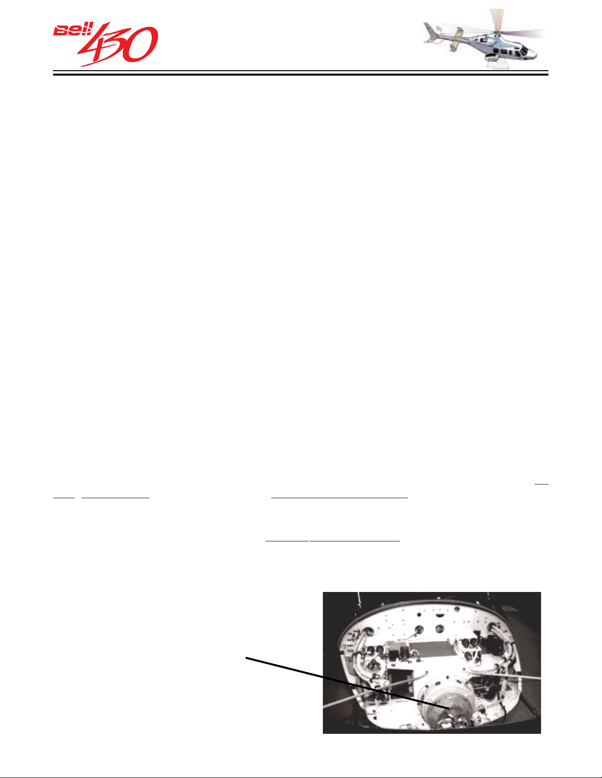
THIS ELECTRONIC DOCUMENT MAY HAVE BEEN SUPERCEDED.
THE MOST CURRENT DOCUMENT INFORMATION IS AVAILABLE
THIS IS AN UNCONTROLLED DOCUMENT.
FROM YOUR BELL HELICOPTER TEXTRON REPRESENTATIVE.
CHIP DETECT OR PO WER UNIT (CDPU)
The Chip Detector Power Unit (CDPU) interfaces with 11 chip detectors and provides
individual outputs to the Integrated Instrument Display System (IIDS) for annunciation.
The CDPU continuously monitors each chip detector to ensure detector and wiring integrity.
Any discontinuity will be annunciated by activating the related detector output and the
single failure signal. Upon a chip signal, the CDPU will activate the related detector
signal output and the single chip signal. Both the failure and chip signal will be active
for 2 seconds only in order to be properly recorded by the IIDS. This will allow proper
recognition of individual chip or failure signals by IIDS. The CDPU will sequentially
send a failure signal or a chip signal to allow the IIDS to properly recognize a failure
condition for the individual chip detector(s). The CDPU will keep the individual detector
annunciation output active until the chip is cleared or the failure condition has disappeared.
If an individual chip input changes state from a failure signal or chip signal, the CDPU
will interrupt the individual signal and resend it with the proper recognition of the occurrence
for the IIDS. The CDPU will either accept a ground input for system self test or be able
to self test upon power-up. The test sequence will last about 6 seconds and trigger one
chip signal for each engine and one for the transmission. The CDPU will accept a signal
input from the IIDS to initiate chip burn off of the related chip detector. Upon CDPU
failure, the chip detectors will be automatically transferred to the IIDS inputs for
annunciation of chip signals. The CDPU will then output a continuous failure signal.
ELECTRICAL SYSTEM
DU AL GENERATORS & BA TTERY
The Bell 430 is equipped with a 28 volt DC single conductor electrical system, using
the helicopter structure as a negative ground. Electric power is supplied by two
volt, 200 ampere starter generators [derated to 180 amperes for continuous operation
up to 5000 feet (1524 meters) pressure altitude; with a further reduction of 2 amperes
per 1000 feet [305 meters] increase in pressure altitude up to 20,000 feet (6096 meters)],
one mounted on each engine, and one
24 volt, 28 ampere-hour nickel-cadmium battery located in the aft electrical compartment, just aft of the baggage compartment door on the right side of the aircraft.
AMPLE SPACE FOR OPTIONAL
AVIONICS EXISTS IN THE
NOSE COMPARTMENT
[SHOWN WITH OPTIONAL
WEATHER RADAR]
30
PRODUCT DATA JANUARY 2003
72
Page 73
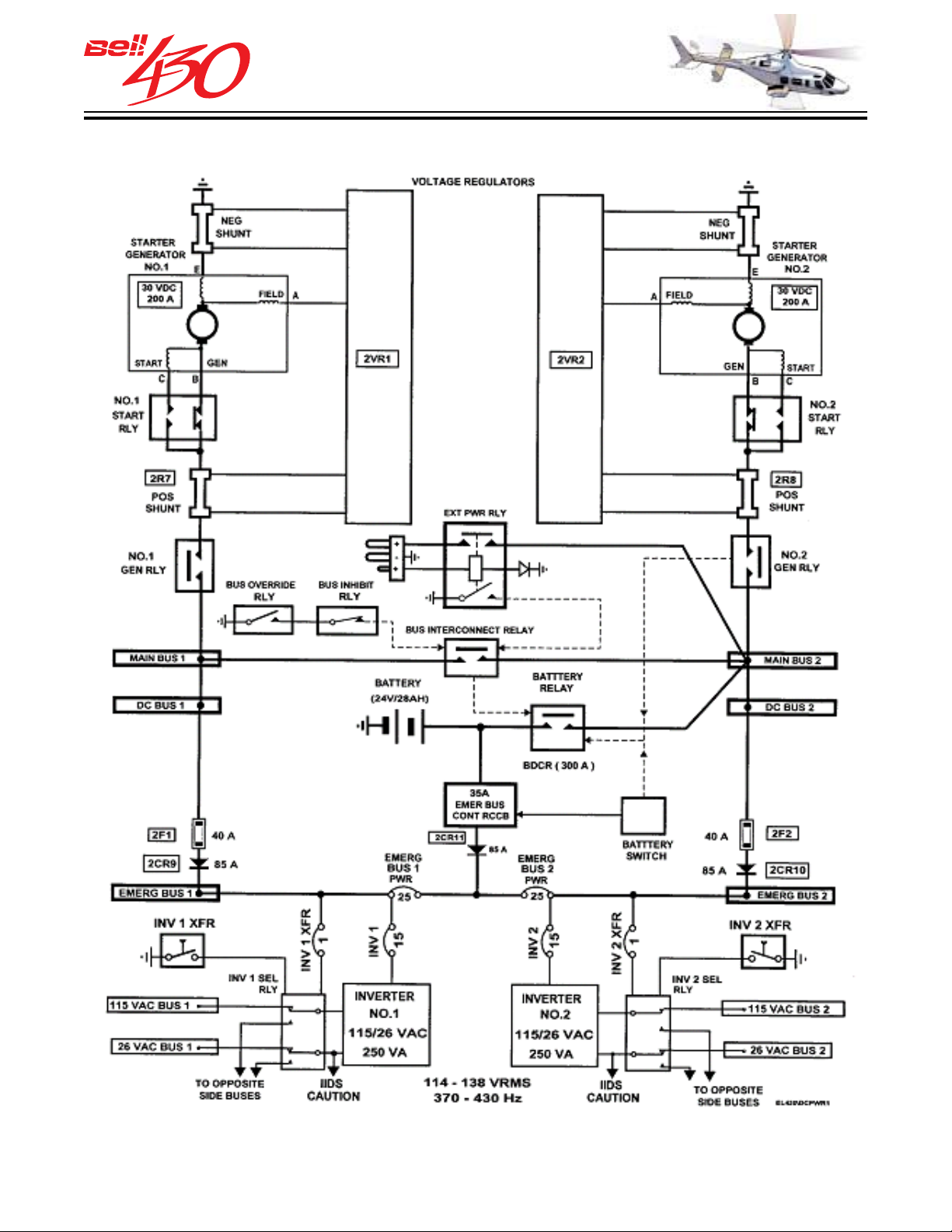
THIS ELECTRONIC DOCUMENT MAY HAVE BEEN SUPERCEDED.
THE MOST CURRENT DOCUMENT INFORMATION IS AVAILABLE
THIS IS AN UNCONTROLLED DOCUMENT.
FROM YOUR BELL HELICOPTER TEXTRON REPRESENTATIVE.
ELECTRICAL POWER DISTRIBUTION SCHEMATIC
PRODUCT DATA JANUARY 2003
73
Page 74
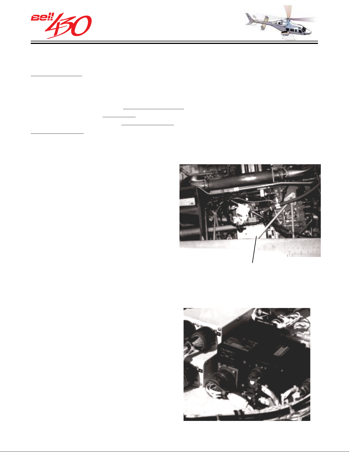
THIS ELECTRONIC DOCUMENT MAY HAVE BEEN SUPERCEDED.
THE MOST CURRENT DOCUMENT INFORMATION IS AVAILABLE
THIS IS AN UNCONTROLLED DOCUMENT.
FROM YOUR BELL HELICOPTER TEXTRON REPRESENTATIVE.
POWER DISTRIBUTION
Electrical power is distributed by two independent subsystems, which may be
interconnected in the event of a generator failure. System protection is accomplished
with relays, circuit breakers, fuses, and isolation diodes. In normal operation, each
generator supplies 28 VDC power, controlled by individual fault sensing voltage
regulators, to a DC bus, and an EMERGENCY bus. Items considered ESSENTIAL for
flight are connected to the
are connected to the
DC buses. Loss of either generator will cause the loss of its' DC
bus, but not the loss of its'
emergency buses, while items NONESSENTIAL for flight
emergency bus, which is interconnected to the opposite
emergency bus. The failed DC bus may have power restored by activating the bus
interconnect relay (BUS INTCON switch).
FAULT PR OTECTION
The bus interconnect relay is inhibited from
closing if a bus / feeder fault (short circuit)
exists. This is to prevent connection of the
operative generator to a faulty circuit.
Diodes prevent reverse current flow from
the emergency buses to the failed DC bus.
The emergency buses are fault protected
from each other by two EMER BUS PWR
circuit breakers, while the DC buses are
guarded from ground faults in an
emergency bus by two 40 amp fuses.
STARTER GENERATOR NO.2
•EXAMPLE•
VOLTAGE REGULAT OR
Each starter-generator is controlled by a
separate solid state voltage regulator,
located in the aft electrical compartment.
They monitor generator output voltage,
control the generator relays, energize the
DC GEN warning lights, and monitor shunt
voltage for fault protection and to prevent
overcurrent.
PRODUCT DATA JANUARY 2003
74
Page 75
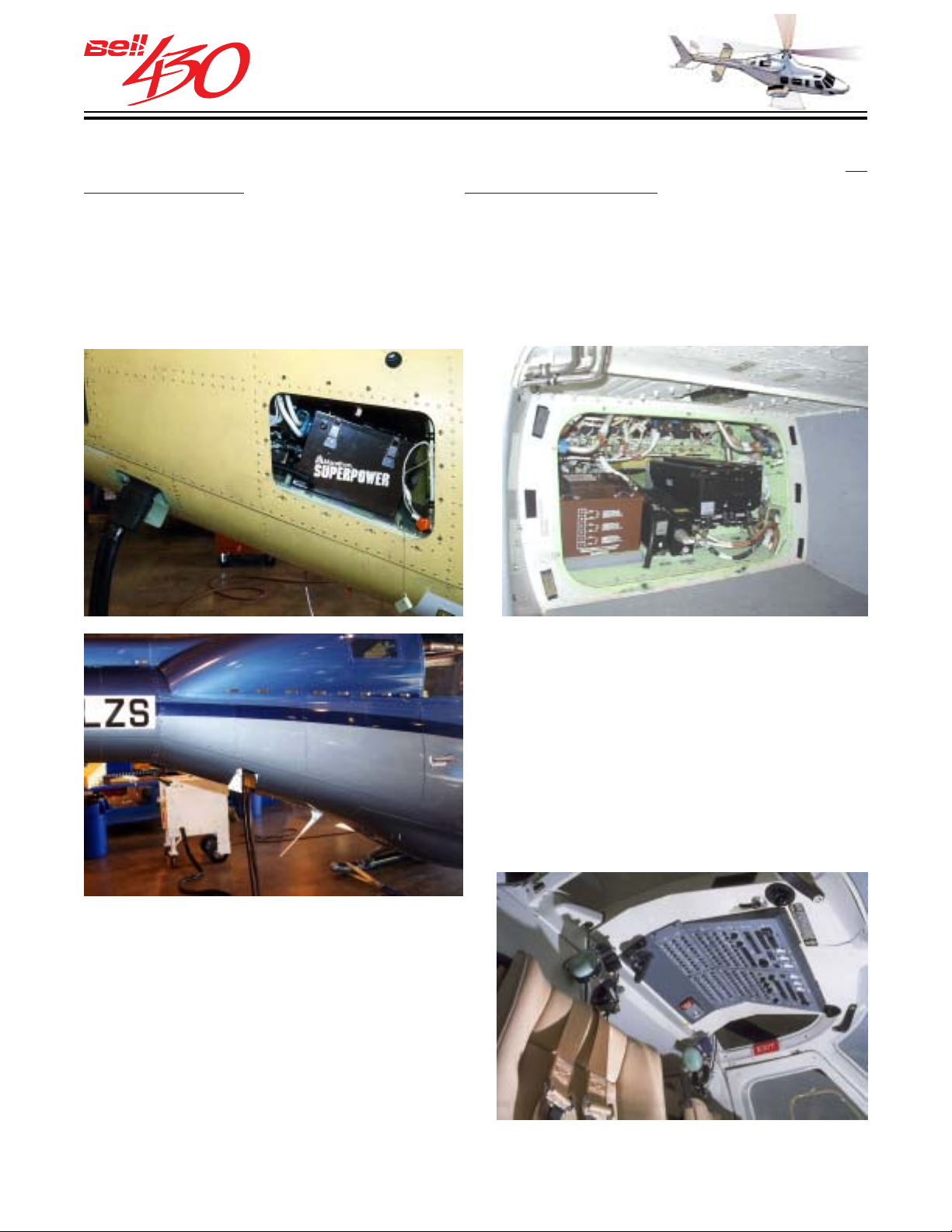
THIS ELECTRONIC DOCUMENT MAY HAVE BEEN SUPERCEDED.
THE MOST CURRENT DOCUMENT INFORMATION IS AVAILABLE
THIS IS AN UNCONTROLLED DOCUMENT.
FROM YOUR BELL HELICOPTER TEXTRON REPRESENTATIVE.
BATTERY POWE R
If a dual generator failure occurs, the battery is sized to provide a minimum of 30
minutes operation, when powering only the two emergency buses. Power may be restored
to the DC BUSES, using the battery as source, but a reduced operating time will result.
The battery contains three temperature sensors; two provide input to the IIDS warning
and caution displays, while one monitors temperature during external power operation
(battery charging) and automatically opens the EXTERNAL POWER relay if an
overtemperature occurs. The battery is attached to the helicopter electrical system
with a standard quick-disconnect plug.
EXTERNAL POWER
A connector for standard 28 volt DC aircraft
ground power unit (GPU) is located on the
helicopter nose, protected by a small hinged
cover. After a ground power start, both
engines should be operating and the GPU
unplugged prior to placing either generator
on line, due to voltage incompatibility.
INVERTERS
Two 250 volt ampere, solid state inverters
supply both 115 and 26 volt AC ( alternating
current). Each inverter [No.1 & No.2] is
powered by respective EMERGENCY BUS
1and EMERGENCY BUS 2.
PRODUCT DATA JANUARY 2003
75
Page 76
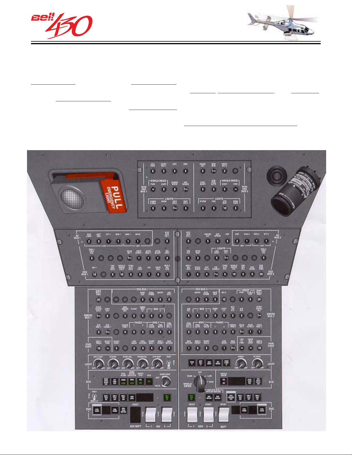
THIS ELECTRONIC DOCUMENT MAY HAVE BEEN SUPERCEDED.
THE MOST CURRENT DOCUMENT INFORMATION IS AVAILABLE
THIS IS AN UNCONTROLLED DOCUMENT.
FROM YOUR BELL HELICOPTER TEXTRON REPRESENTATIVE.
OVERHEAD CONSOLE
The overhead console, centered on the cockpit ceiling, contains most of the electrical
switches and circuit breakers. The console has two sides , with the circuit breakers of
Subsystem 1 on the left, and Subsystem 2 on the right. Five rocker-type switches at
the consoles' central forward edge control the Battery, Generator 1 & 2, the Inverter,
and the
with white light. Except for the DC bus control switches (white illuminated), the remaining push-on / push-off switches change illumination color from white to green when activated. The internal lighting controls are
is ample space reserved for circuit breakers and switches required by optional equipment.
Emergency Light. The rocker switches are clearly labeled and internally illuminated
potentiometer knobs or rheostats. There
PRODUCT DATA JANUARY 2003
76
Page 77
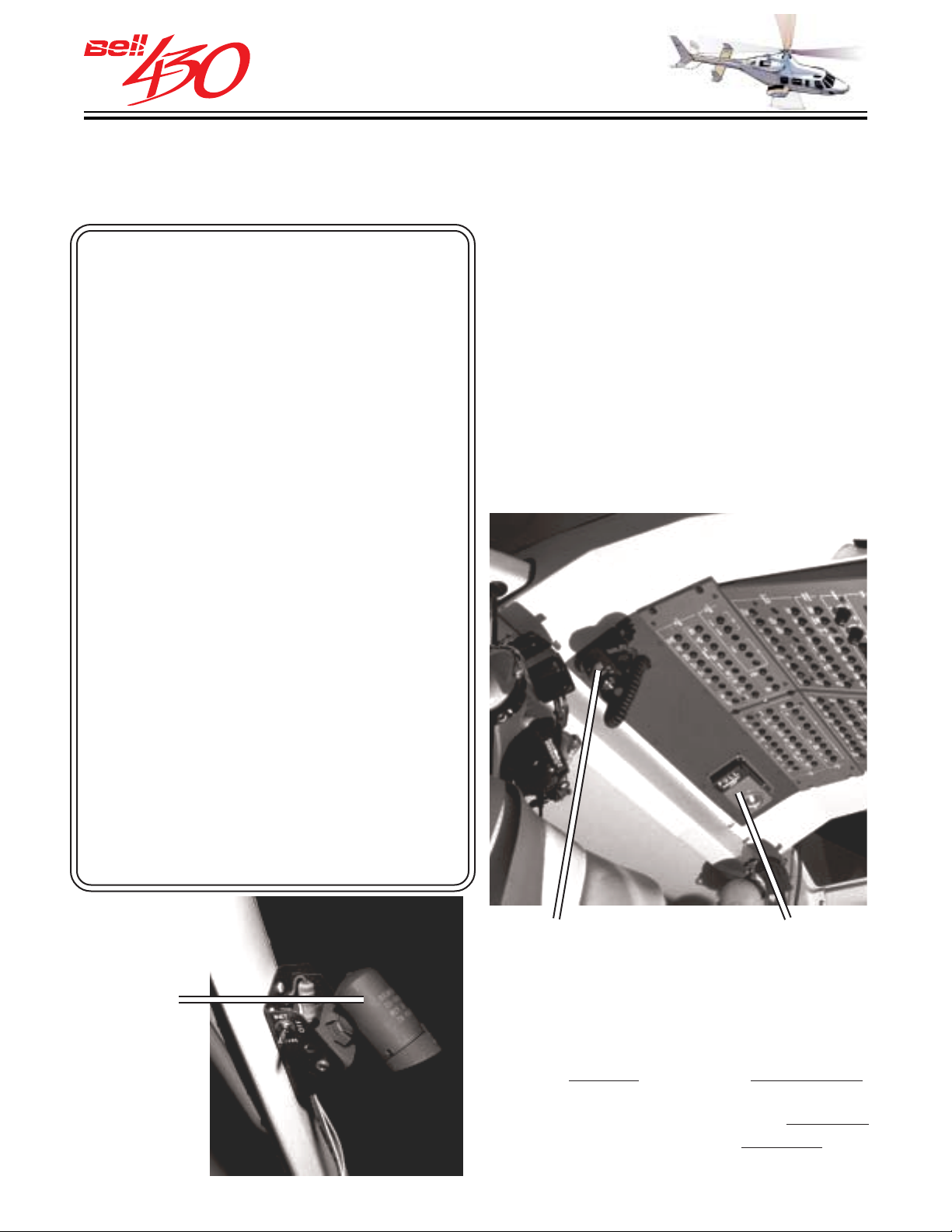
THIS ELECTRONIC DOCUMENT MAY HAVE BEEN SUPERCEDED.
THE MOST CURRENT DOCUMENT INFORMATION IS AVAILABLE
THIS IS AN UNCONTROLLED DOCUMENT.
FROM YOUR BELL HELICOPTER TEXTRON REPRESENTATIVE.
LIGHTING
The Bell 430 in standard configuration is completely equipped for night operations.
The following lights are provided:
COCKPIT LIGHTING
One co ckpit utility light, with red
/ white-spot / flood beam
Two map lights
One cockpit emergency light
Internal white instrument lights
Storm Lights (external
instrument illumination)
Pedestal equipment lighting
The instruments, information panels, panel
mounted avionics, pedestal and overhead
console are uniformly illuminated with
integral blue / white lighting. Separate
dimming rheostats are provided for the
pilot's flight instruments, engine
instruments, the map lights, pedestal
mounted equipment, overhead console,
and the cabin lights. Provisions are included
for dimming the optional copilot
instruments.
Overhead console lighting
Four cabin dome lights, with
integral battery powered
emergency lights
Four luminescent panels (over
each emergency exit)
Seat belt / No Smoking sign
Baggage compartment light
Position lights
Retractable Landing / Sear ch
light
Two anticollision lights
UTILITY LIGHT EMERGENCY LIGHT
UTILITY LIGHT
APPROACH
PLATE/MAP
LIGHT
PRODUCT DATA JANUARY 2003
A single dimable utility light [GRIMES
LIGHT] is provided just inboard of the roof
window above the pilot. It may be pointed
from its'
be removed and used anywhere in the
cockpit. The light beam may be
from white to red light, and adjusted from
spot to flood.
bracket, or with the coiled cable,
switched
77
Page 78
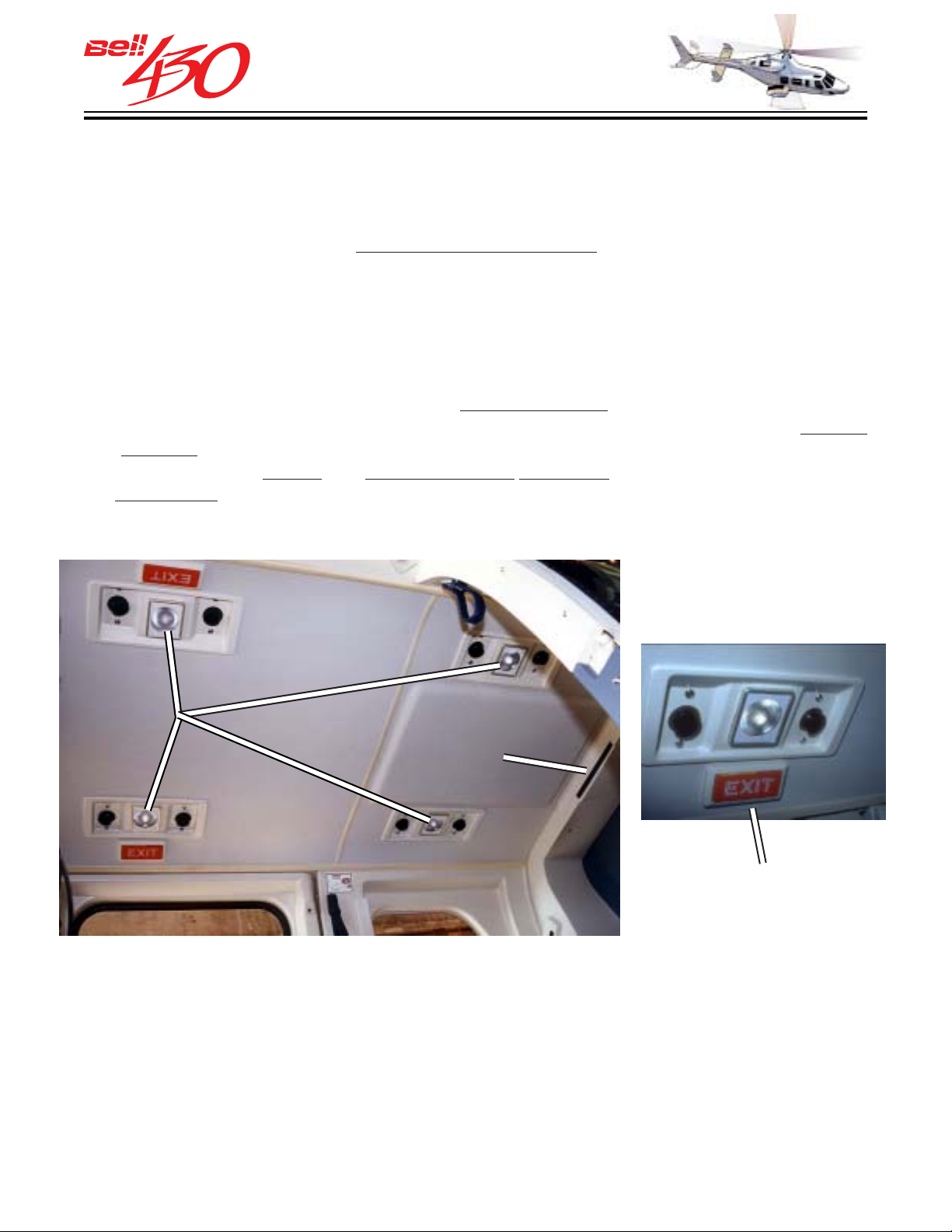
THIS ELECTRONIC DOCUMENT MAY HAVE BEEN SUPERCEDED.
THE MOST CURRENT DOCUMENT INFORMATION IS AVAILABLE
THIS IS AN UNCONTROLLED DOCUMENT.
FROM YOUR BELL HELICOPTER TEXTRON REPRESENTATIVE.
EMERGENCY LIGHT
A battery powered emergency light is mounted at the rear of the overhead console,
directed toward the instrument panel. The batteries are kept fully charged by the helicopters
electrical system (EMERG BUS 2), and when the EMERGENCY LIGHT SWITCH is armed,
automatically turns on should
both emergency buses fail. It will provide illumination for
about 20 minutes, and may be removed for use as a flashlight.
CABIN LIGHTING
Four cabin dome lights provide adjustable interior illumination. Controlled by a switch
(CABIN & BAG LT) on the overhead console, their intensity can be adjusted by the
pilot. Each dome light contains a separate
by the EMERGENCY LIGHT SWITCH . Two Ni-Cad batteries (one each for the two left
two right lights) are kept fully charged by the electrical system. Activation is automatic
and
when the system is armed and both emergency buses fail. The batteries are sufficient
20 minutes of illumination.
for
battery powered emergency light, controlled
DOME
LIGHTS
NO SMOKING
LIGHT
BETA
LIGHT
DETAIL
EMERGENCY EXIT LIGHTS
Self illuminated BETA lights are mounted over each window in the crew / passenger
doors to identify the emergency exits.
SEAT BEL T / NO SMOKING SIGN
An illuminating sign with the international symbols for FASTEN SEAT BELTS and NO
SMOKING is displayed at the rear of the overhead console, visible to the cabin occupants.
Each sign segment is individually controllable by a switch above the pilot.
PRODUCT DATA JANUARY 2003
78
Page 79
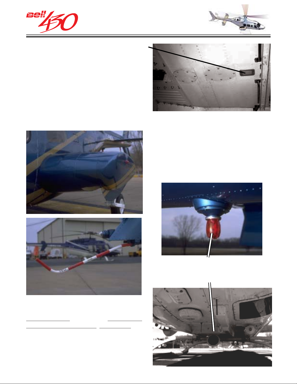
THIS ELECTRONIC DOCUMENT MAY HAVE BEEN SUPERCEDED.
THE MOST CURRENT DOCUMENT INFORMATION IS AVAILABLE
THIS IS AN UNCONTROLLED DOCUMENT.
FROM YOUR BELL HELICOPTER TEXTRON REPRESENTATIVE.
BA GGAGE COMPARTMENT LIGHT
The baggage compartment contains a
single light mounted in its' ceiling,
controlled by the same circuit which
activates the cabin dome lights.
EXTERNAL LIGHTING
POSITION LIGHTS
Standard aviation position lights are
provided; a green light on the right wing, a
red light on the left wing, and a white light
on the tail.
ANTI COLLISION LIGHTS
Two highly conspicuous red strobe lights
serve to draw attention in flight or on the
ground. One is located above the engine
cowling, and another is found on the
underside of the tail boom.
LOWER ANTICOLLISION LIGHT
DIRECTIONALLY CONTROLLABLE
LANDING/SEARCH LIGHT
SEARCH / LANDING LIGHT
The search and landing light is a single,
high intensity, 450 watt , wide-beam,
directionally controllable, retractable light
located in the lower part of the fuselage.
The ON / OFF / STOW power switch and
four-way steering switch are located on the
pilots' collective control box.
PRODUCT DATA JANUARY 2003
79
Page 80
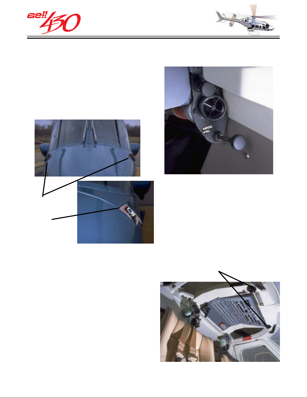
THIS ELECTRONIC DOCUMENT MAY HAVE BEEN SUPERCEDED.
THE MOST CURRENT DOCUMENT INFORMATION IS AVAILABLE
THIS IS AN UNCONTROLLED DOCUMENT.
FROM YOUR BELL HELICOPTER TEXTRON REPRESENTATIVE.
CREW VENTILATION / WINDSHIELD DEFOGGING
Two separate systems, pilot and forward
passenger position, provide for crew
ventilation and windshield defogging. Each
system consists of an exterior plenum door
(on one side of the nose), an electric blower,
diverter valve, ducting, check valve,
windshield defog nozzle, adjustable vent
nozzle, and two control cable assemblies.
LEFT & RIGHT
COCKPIT
AIR INLETS
[DETAIL]
LOWER CREW AIR OUTLET
Provision is made for the defog nozzles
connection to heated air ducts from the
optional Environmental Control System,
when installed.
Additional cockpit ventilation is provided
from two overhead outlets which receive
air from the cabin ventilation system.
The two cable assembly control knobs
located above and below each vent nozzle
UPPER CREW AIR OUTLETS
control the plenum door and the diverter
valve. Pressing the center of each knob
and sliding the cable out or in varies the
door opening (upper knob), or diverts
airflow (lower knob) to the defog nozzle.
Releasing the center of the knob locks the
cables position. The vent nozzles, located
on either side of the instrument panel may
be adjusted for direction and volume. Each
system will function with ram air only, or
for ground / hovering operation, with the
vent blowers (PILOT VENT BLO & CPLT
VENT BLO switches on the overhead
console).
PRODUCT DATA JANUARY 2003
80
Page 81
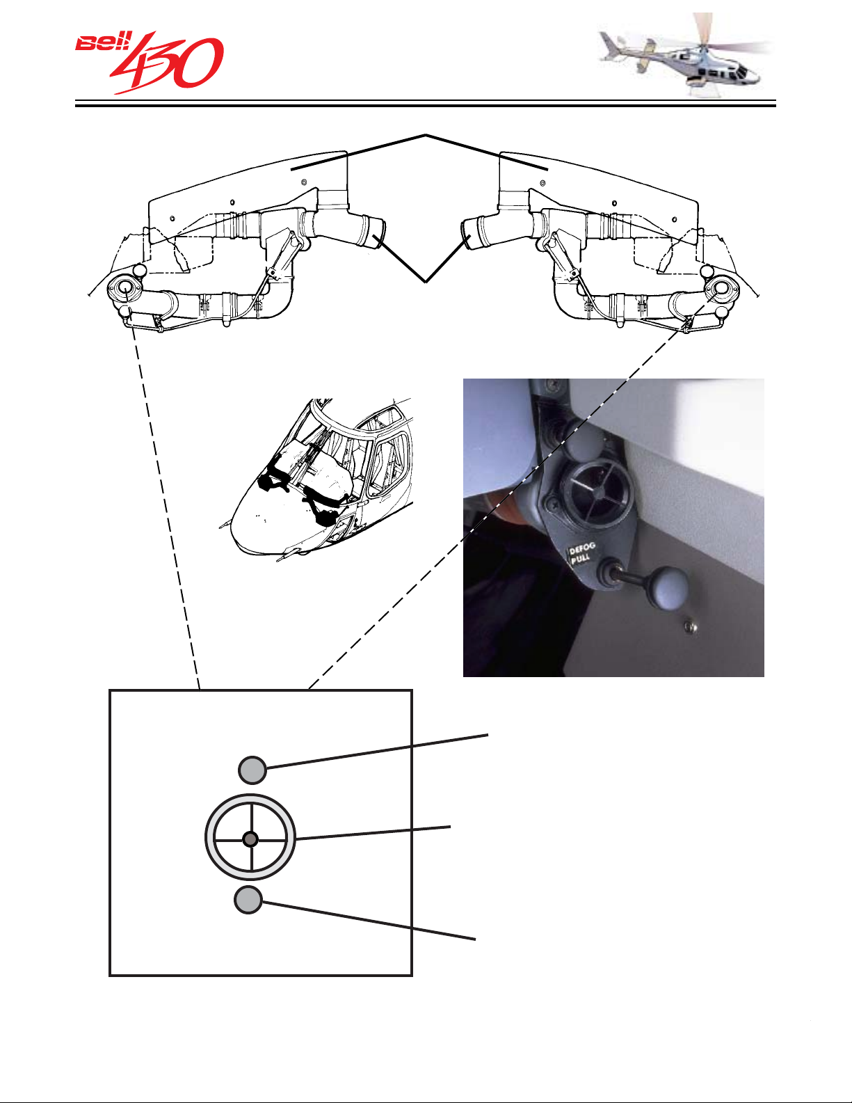
THIS ELECTRONIC DOCUMENT MAY HAVE BEEN SUPERCEDED.
THE MOST CURRENT DOCUMENT INFORMATION IS AVAILABLE
THIS IS AN UNCONTROLLED DOCUMENT.
FROM YOUR BELL HELICOPTER TEXTRON REPRESENTATIVE.
DEFOG NOZZLES
[ PROVISION FOR OPTIONAL
ECU / BLEED AIR HEAT]
UPPER CABLE CONTROL
OPENS PLENUM DOOR
VENT OUTLET -ROTATE CLOCKWISE TO
CLOSE -COUNTER CLOCKWISE TO OPEN
LOWER CABLE CONTROL
DIVERTS AIRFLOW TO DEFOG
PRODUCT DATA JANUARY 2003
81
Page 82
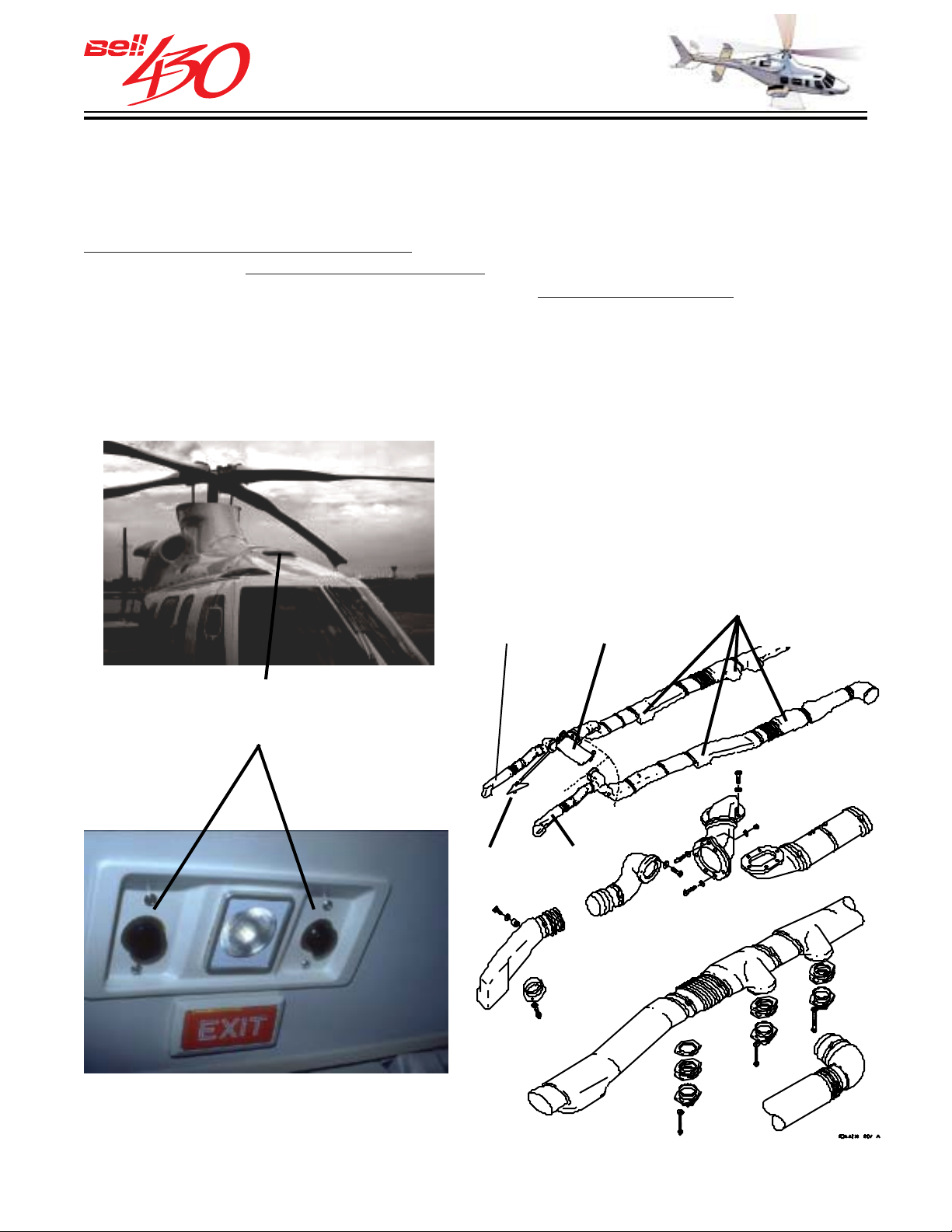
THIS ELECTRONIC DOCUMENT MAY HAVE BEEN SUPERCEDED.
THE MOST CURRENT DOCUMENT INFORMATION IS AVAILABLE
THIS IS AN UNCONTROLLED DOCUMENT.
FROM YOUR BELL HELICOPTER TEXTRON REPRESENTATIVE.
CABIN VENTILATION
The cabin interior is ventilated with ambient ram air . The ram air enters an inlet scoop
on the roof, which is controlled by a lever above the pilot's head, and is directed through
a plenum into two parallel distribution ducts. Four dual outlets are installed in the
passenger compartment headliner (combined with the four cabin lights), with two
additional outlets
Each of the outlets is separately controllable in direction and volume. Air exhausts
from the cabin through two ports, left and right, near the floor, at the lower edge of the
rear bench seat. The ports may be opened or closed by hand to help adjust the flow.
The minimum cabin air exchange rate in cruise flight is 2.83 cubic meters per minute
(100 cubic feet per minute).
just above the windshields in front of the pilot and forward passenger.
CABIN AIR DISTRIBUTION SYSTEM
1. Pilots overhead vent duct
2. Passenger vent door
3. Passenger vent ducts
4. Copilots overhead vent duct
5. Vent control knob and lever
CABIN AIR SCOOP
ONE CABIN VENT AND LIGHT GROUP
3
1
5
2
4
PRODUCT DATA JANUARY 2003
82
Page 83
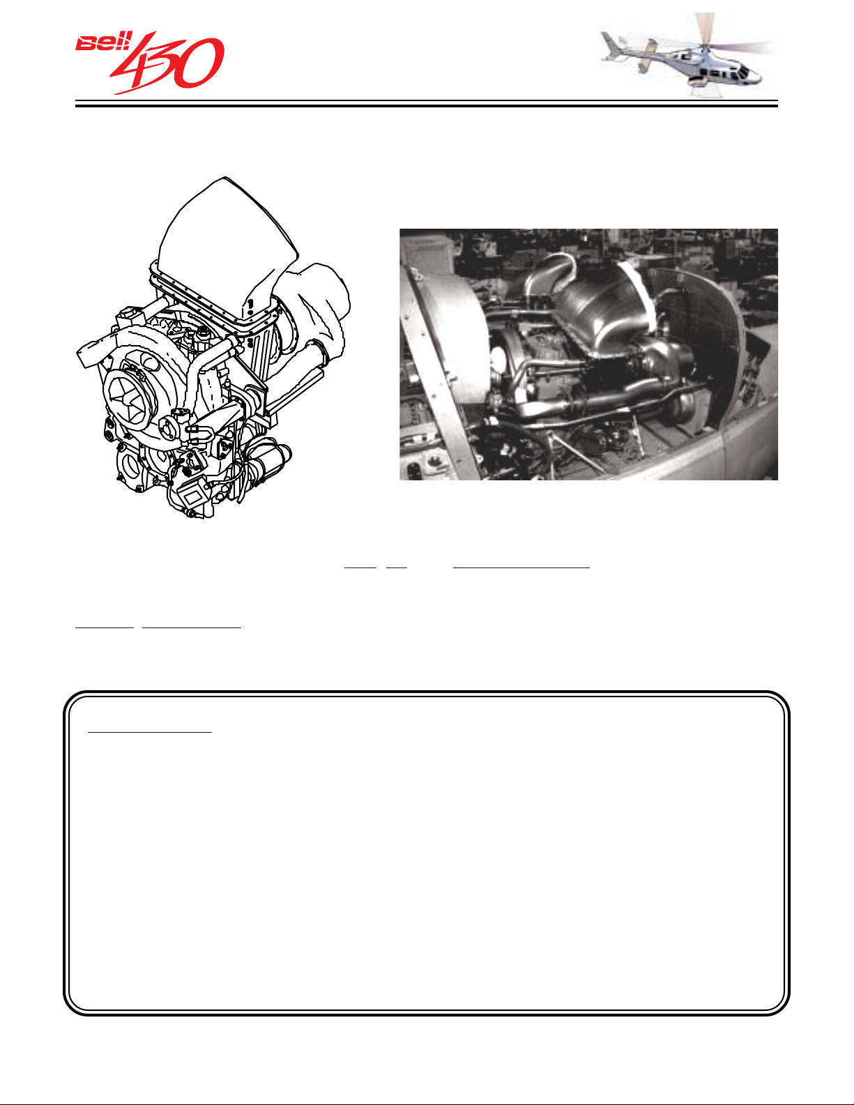
THIS ELECTRONIC DOCUMENT MAY HAVE BEEN SUPERCEDED.
THE MOST CURRENT DOCUMENT INFORMATION IS AVAILABLE
THIS IS AN UNCONTROLLED DOCUMENT.
FROM YOUR BELL HELICOPTER TEXTRON REPRESENTATIVE.
POWERPLANT
TWO ROLLS-ROYCE 250-C40B TURBOSHAFT ENGINES
The powerplant consists of two Rolls-Royce Gas Turbine Model 250-C40B turboshaft
engines and their independent fuel, oil, and air management systems. The engines
are mounted side-by-side, in individual fireproof compartments; the left side designated
ENGINE NO. 1 and the right side as ENGINE NO. 2. Optimized for performance under
hot day, high altitude conditions, there is ample reserve power contained in each compact
118 kilogram (260 pound) unit.
Uninstalled
ENGINE RATINGS:
Thermodynamic
Power
Rolls-Royce 250-C40B with Full Authority Digital Electronic Control (FADEC).
Takeoff Power (5 Minutes) SHP(kW) 808(603) 747(557)
Maximum Continuous Power SHP(kW) 695(518) 618(461)
OEI (30 seconds) SHP(kW) 940(701) 844(629)
OEI (2 minute) SHP(kW) 880(656) 811(605)
OEI (30 minute) SHP(kW) 835(623) 789(588)
Engine Rated
Power
OEI (Continuous) SHP(kW) 808(603) 747(557)
PRODUCT DATA JANUARY 2003
83
Page 84
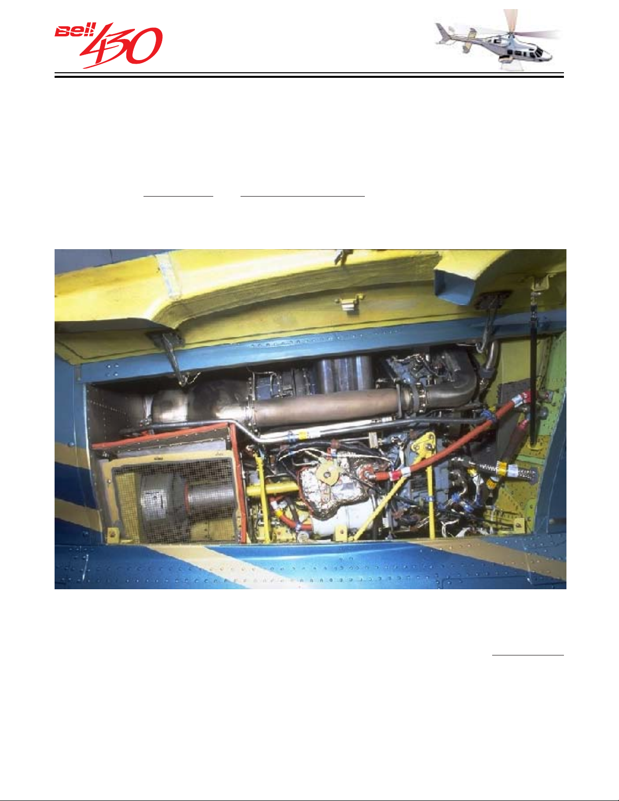
THIS ELECTRONIC DOCUMENT MAY HAVE BEEN SUPERCEDED.
THE MOST CURRENT DOCUMENT INFORMATION IS AVAILABLE
THIS IS AN UNCONTROLLED DOCUMENT.
FROM YOUR BELL HELICOPTER TEXTRON REPRESENTATIVE.
RELIABLE POWER
Manufactured by Rolls Royce, the C40B is one of the latest in the evolutionary Model
250 series, which has amassed over 100 million engine flight hours. During this
evolution, many improvements have been incorporated.
The engine is light weight and of compact. Easy to maintain, all engine adjustments
and almost all
engine remains installed on the helicopter.
inspections and routine maintenance can easily be performed while the
MODULAR CONSTRUCTION
The Rolls-Royce 250-C40B turboshaft engine features modular design for easy access
to the major components. One module can be replaced quickly without disturbing the
others. Modular design offers substantial direct operating cost advantages because
maintenance or overhaul of a single module can be accomplished independently. The
compressor, for instance, may be removed for repair or overhaul while the remainder
of the engine continues in service with a replacement (overhaul exchange unit / temporary
leased) compressor.
PRODUCT DATA JANUARY 2003
84
Page 85
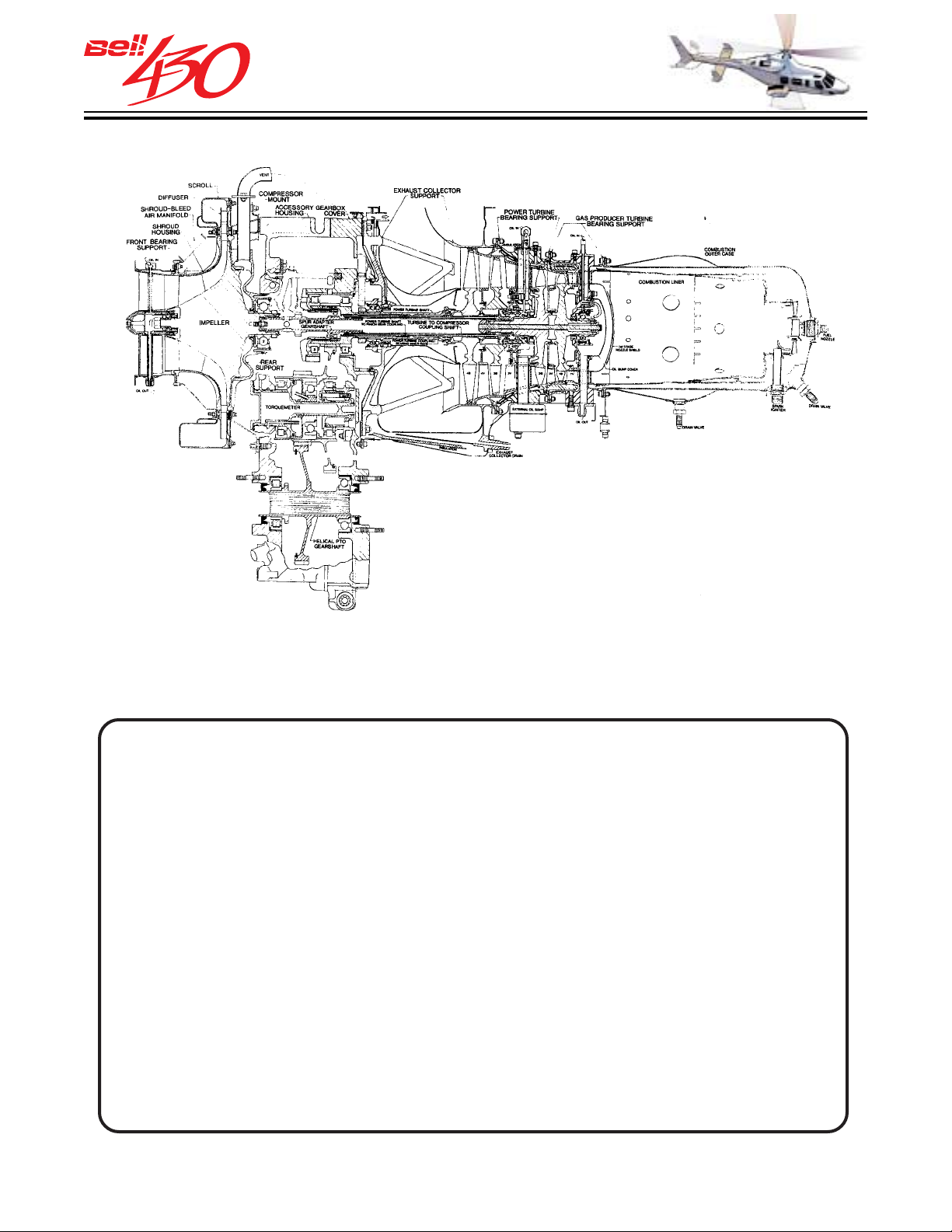
THIS ELECTRONIC DOCUMENT MAY HAVE BEEN SUPERCEDED.
THE MOST CURRENT DOCUMENT INFORMATION IS AVAILABLE
THIS IS AN UNCONTROLLED DOCUMENT.
FROM YOUR BELL HELICOPTER TEXTRON REPRESENTATIVE.
ENGINE CUTAWAY SCHEMATI C
The two engines are identical, each consisting of four major modules; a compressor
section, an accessory gear box, a turbine section and a combustion section. Some
of the benefits of the modular concept are shown below.
COMPRESSOR MODULE TURBINE MODULE
•READY FOR OVERHAUL OR REPAIR BY
REMOVING SIX GEARBOX MOUNTING
BOLTS.
•SIMPLE SINGLE STAGE IMPELLER.
•NO VARIABLE GEOMETRY.
•MOUNTED TO THE REAR OF THE
GEARBOX WITH FIVE NUTS.
•FIRST STAGE TURBINE ACCESSIBLE BY
REMOVING THE COMBUSTOR MODULE.
•ALL ACCESSORIES AND SHAFTING
REMAIN IN PLACE.
GEARBOX MODULE
• RUGGED CONSTRUCTION, COM-
MON MOUNTING PADS FOR ALL
MODEL 250 SERIES ENGINES.
•ALL LIP SEALS CHANGED EXTERNALLY.
•ROTATING ACCESSORIES USE COMMON
NUTS.
•BOTH FRONT AND REAR DRIVE.
•EASY ACCESS TO THE ACCESSORIES
FOR QUICK REMOVAL AND
REPLACEMENT.
COMBUST OR MODULE
•SIMPLE ONE PIECE OUTER
COMBUSTOR, SINGLE COMBUSTOR
LINER.
•SINGLE FUEL NOZZLE.
•SINGLE SPLIT LINE FOR REMOVAL
FROM TURBINE.
•COMPLETE COMBUSTOR SYSTEM
HARDWARE CAN BE INSPECTED BY
REMOVAL OF COMBUSTOR MODULE.
PRODUCT DATA JANUARY 2003
85
Page 86
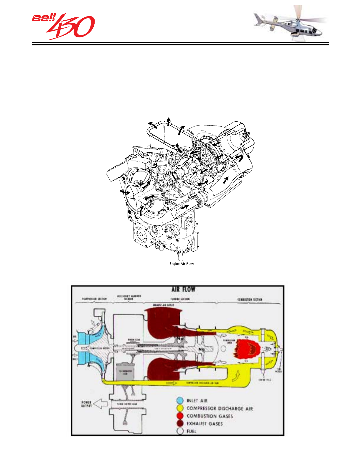
THIS ELECTRONIC DOCUMENT MAY HAVE BEEN SUPERCEDED.
THE MOST CURRENT DOCUMENT INFORMATION IS AVAILABLE
THIS IS AN UNCONTROLLED DOCUMENT.
FROM YOUR BELL HELICOPTER TEXTRON REPRESENTATIVE.
OPERATING PRINCIPLES
The basic principle of the C40B engine is quite simple; continuous combustion that produces a steady flow of efficient power. Air is supplied to each engine through airscoops on either side of the fuselage aft of the transmission cowling [ Airflow at takeoff power
is approximately 2.54 kilograms per second (5.6 pounds per second) for each engine].
Before the air enters the engine it passes through a protective screen to prevent the
induction of large foreign matter.
ENGINE AIR FLO W SCHEMATIC
PRODUCT DATA JANUARY 2003
86
Page 87
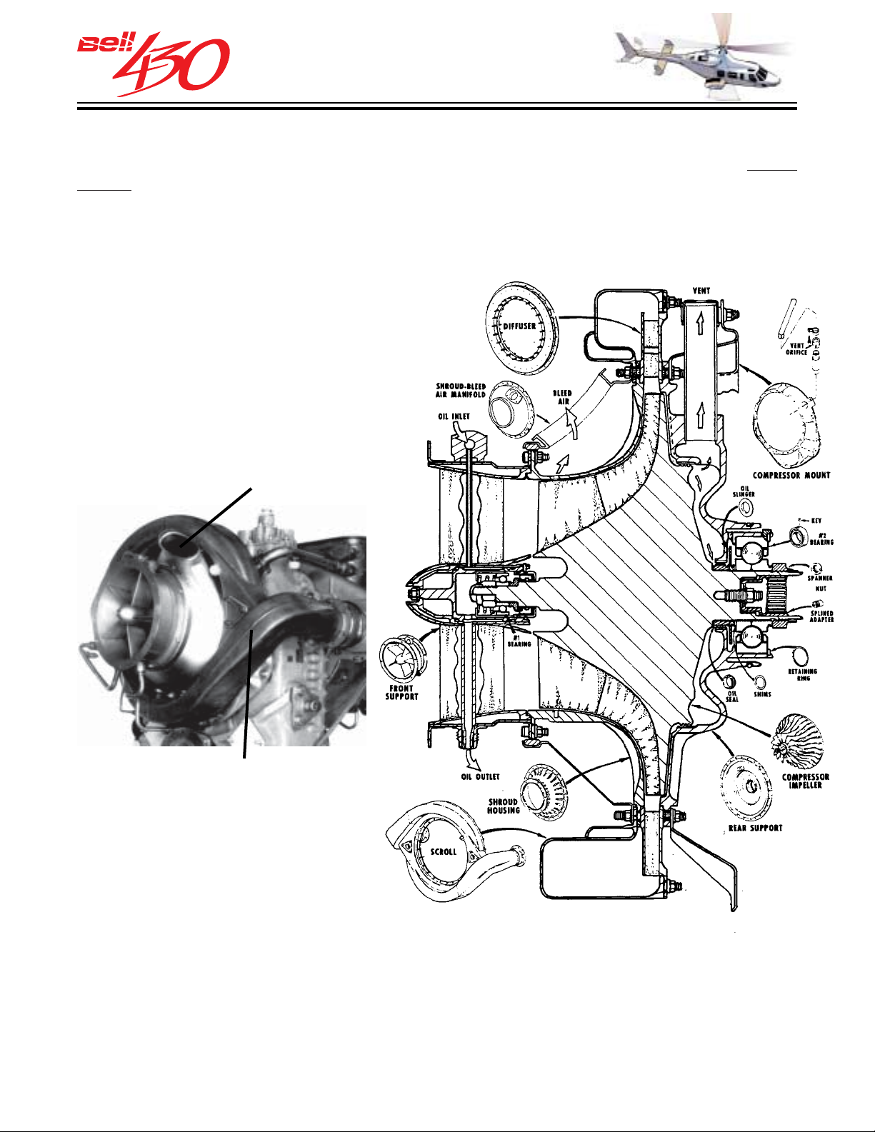
THIS ELECTRONIC DOCUMENT MAY HAVE BEEN SUPERCEDED.
THE MOST CURRENT DOCUMENT INFORMATION IS AVAILABLE
THIS IS AN UNCONTROLLED DOCUMENT.
FROM YOUR BELL HELICOPTER TEXTRON REPRESENTATIVE.
COMPRESSOR SECTION
Clean air enters the compressor inlet. The compressor in the C40B is a titanium single
-stage centrifugal impeller which compresses the entering air ( 8.6 to 1 pressure ratio at takeoff power ) and discharges it through a diffuser assembly and dual scroll collector
into a pair of external ducts. The ducts carry the air directly to the combustion section
at the aft end of the engine.
•EXAMPLE•
BLEED AIR VENT
SCROLL
PRODUCT DATA JANUARY 2003
87
Page 88
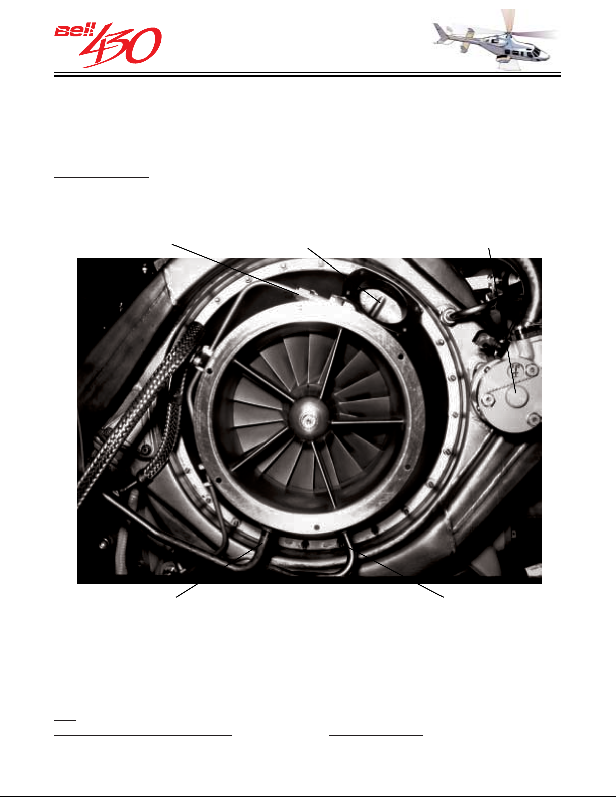
THIS ELECTRONIC DOCUMENT MAY HAVE BEEN SUPERCEDED.
THE MOST CURRENT DOCUMENT INFORMATION IS AVAILABLE
THIS IS AN UNCONTROLLED DOCUMENT.
FROM YOUR BELL HELICOPTER TEXTRON REPRESENTATIVE.
BLEED SYSTEM
An acceleration bleed air system is incorporated in the compressor assembly. The
system allows a portion of the compressed air to escape during the start/acceleration
cycle to prevent stalls, power surges, and to assure rapid response to engine power
demands. The system consists of a
bleed assembly. As NG increases, the bleed valve gradually closes to reserve air for
engine operation. The inducer bleed serves a similar function to enhance compressor
efficiency when NG is above 96 %.
pneumatically operated bleed valve, and an inducer
NO. 1 BRG. OIL IN
INDUCER
BLEED PORT
ACCELERATION
BLEED VALVE
ANTI-ICING AIR NO. 1 BRG. OIL OUT
•EXAMPLE PHOTO•
BLEED AIR SOURCES
Four ports along the diffuser scroll are provided to supply bleed air.
to the engine fuel system, a second is for to the anti-icing system, and the remaining
two are available as bleed air sources to power airframe systems (optional environmental control system or customized bleed air heater).
PRODUCT DATA JANUARY 2003
88
One provides air
Page 89
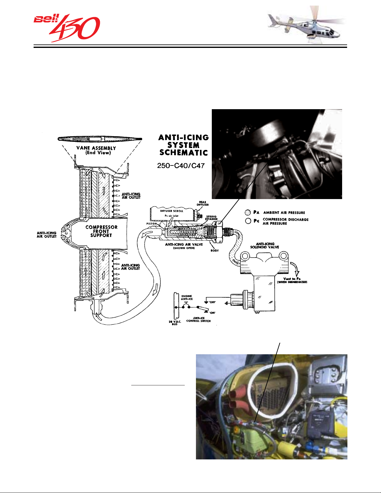
THIS ELECTRONIC DOCUMENT MAY HAVE BEEN SUPERCEDED.
THE MOST CURRENT DOCUMENT INFORMATION IS AVAILABLE
THIS IS AN UNCONTROLLED DOCUMENT.
FROM YOUR BELL HELICOPTER TEXTRON REPRESENTATIVE.
ANTI-ICING SYSTEM
The anti-icing system directs hot compressor discharge air through the inlet guide vanes to prevent the ice formation on the hollow vanes. An electrically operated valve
on the compressor scroll controls the air flow. Anti-icing ON is required when flying
into visible moisture at temperatures below 4.5°C (40°F).
COMPRESSOR WASH FITTING
ENGINE CLEANING
A compressor wash / rinse fitting is
provided to facilitate the
daily compressor cleaning to remove
airborne chemical contamination (such as
when operating near salt water). A spray
nozzle, connecting tubing, and threaded
adapter are installed for each engine to
allow quick conduct of the wash process
without removal of cowlings (or the optional
particle separator kit, if installed)
PRODUCT DATA JANUARY 2003
recommended
89
Page 90
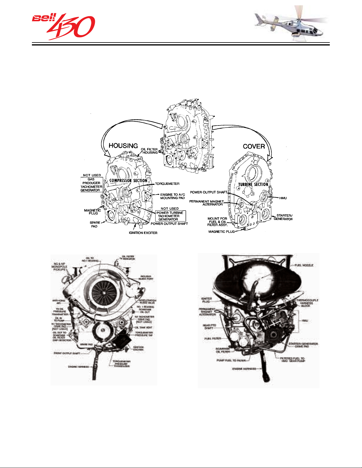
THIS ELECTRONIC DOCUMENT MAY HAVE BEEN SUPERCEDED.
THE MOST CURRENT DOCUMENT INFORMATION IS AVAILABLE
THIS IS AN UNCONTROLLED DOCUMENT.
FROM YOUR BELL HELICOPTER TEXTRON REPRESENTATIVE.
ACCESSORY GEARBOX SECTION
The accessory gearbox section includes a gearbox housing (FRONT or COMPRESSOR
side), a gearbox cover (REAR or TURBINE side), gas producer gear train, power
turbine gear train, oil pump assembly, oil filter, and the necessary oil tubes to provide
pressure and scavenge oil for the system.
PRODUCT DATA JANUARY 2003
90
Page 91
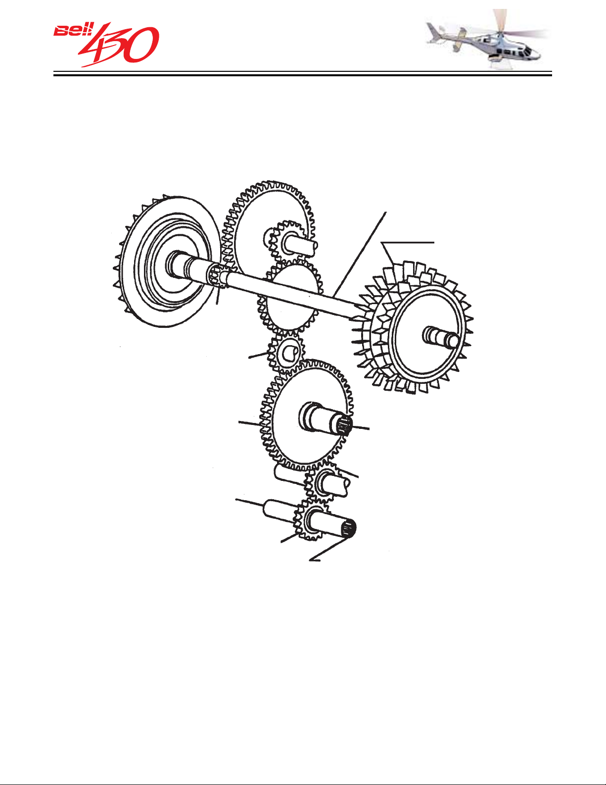
THIS ELECTRONIC DOCUMENT MAY HAVE BEEN SUPERCEDED.
THE MOST CURRENT DOCUMENT INFORMATION IS AVAILABLE
THIS IS AN UNCONTROLLED DOCUMENT.
FROM YOUR BELL HELICOPTER TEXTRON REPRESENTATIVE.
GAS PRODUCER GEARING
The accessory drive train is powered by the gas producer turbine. It drives / is driven
by the starter / generator, and provides power for the engine fuel pump,
hydromechanical unit and the engine oil pump.
[ LEFT IS FORWARD ]
2
COMPRESSOR
COUPLING
3
1
4
TURBINE TO
5
DRIVES FADEC H.M.U.
& ENGINE OIL PUMP
& NG TACHOMETER
6
SPARE
7
STARTER / GENERATOR
DRIVE
1. SPUR ADAPTOR GEARSHAFT
2. SPUR CENTRIFUGAL BREATHER GEARSHAFT
3. SPUR IDLER GEARSHAFT
4. SPUR IDLER GEARSHAFT
5. SPUR HYDRO MECHANICAL UNIT & OIL PUMP & NG TACH GEARSHAFT
6. GENERATOR IDLER GEAR
7. STARTER GENERATOR GEARSHAFT
PRODUCT DATA JANUARY 2003
91
Page 92
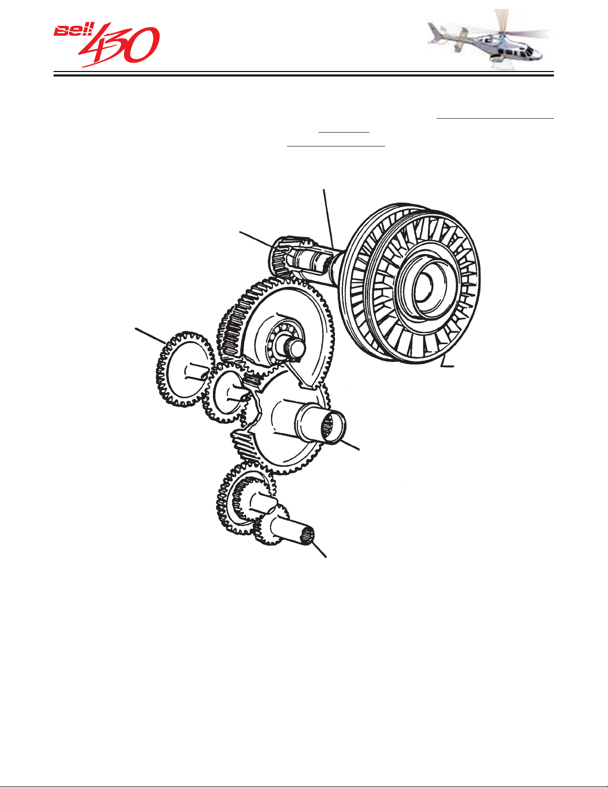
THIS ELECTRONIC DOCUMENT MAY HAVE BEEN SUPERCEDED.
THE MOST CURRENT DOCUMENT INFORMATION IS AVAILABLE
THIS IS AN UNCONTROLLED DOCUMENT.
FROM YOUR BELL HELICOPTER TEXTRON REPRESENTATIVE.
PO WER TURBINE GEARING
The power turbine gear train supplies engine power to the main forward output drive
at a design speed of 9,598 RPM. In addition the
power to operate the airframe mounted
[ LEFT IS FORWARD ]
oil cooler blower.
POWER TURBINE
rear side of the main output drive provides
SHAFT
TURBINE SHAFT TO
PINION GEAR COUPLING
DRIVES P.M.A.
11
13
8
9
10
DELIVERS ENGINE OUTPUT
POWER TO MAIN DRIVESHAFT (FWD)
AND TAIL ROTOR DRIVESHAFT (AFT)
14
8. HELICAL POWERTRAIN DRIVE GEAR
9. HELICAL TORQUEMETER GEARSHAFT
10. HELICAL POWER TAKEOFF GEARSHAFT
11. SPUR POWERTRAIN IDLER GEAR
12. SPUR POWERTRAIN PERMANENT
MAGNET ALTERNATOR
13. SPARE DRIVE IDLER HELICAL SPUR
GEARSHAFT
14. SPARE SPUR DRIVE GEARSHAFT
PRODUCT DATA JANUARY 2003
92
SPARE DRIVE - 15 SHP
SPARE DRIVE P AD S
Each gear train has an additional drive pad
location available for limited use as an
accessory power source, one each on the
front of the gearbox.
Page 93
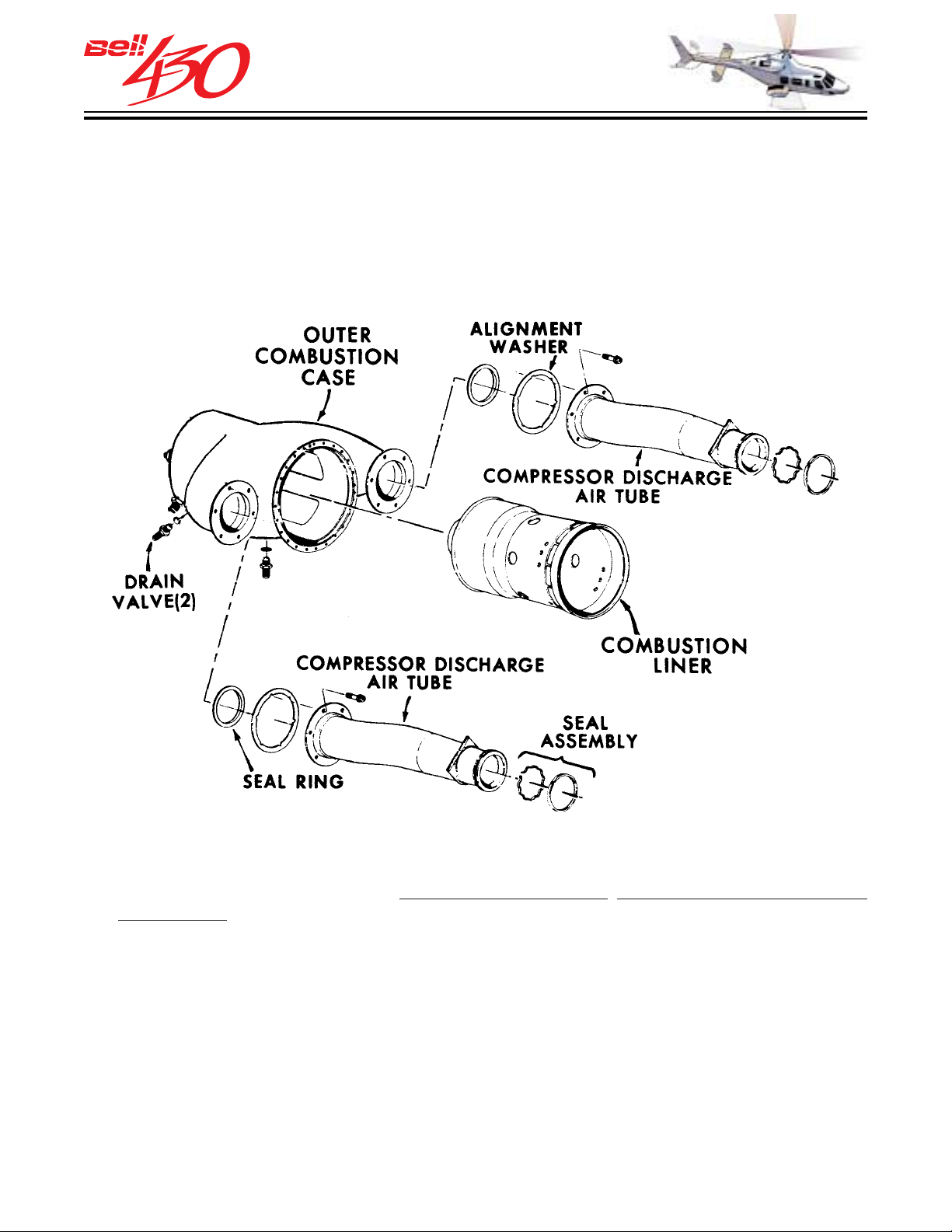
THIS ELECTRONIC DOCUMENT MAY HAVE BEEN SUPERCEDED.
THE MOST CURRENT DOCUMENT INFORMATION IS AVAILABLE
THIS IS AN UNCONTROLLED DOCUMENT.
FROM YOUR BELL HELICOPTER TEXTRON REPRESENTATIVE.
COMBUSTION SECTION
The combustion section consists of an outer case, a combustion liner, an igniter and a
fuel injector. The prechamber combustion system is designed to burn fuel at peak efficiency
and to minimize emissions. Fuel is sprayed into the chamber at a precisely controlled
rate. The single igniter produces a constant spark while the start circuit is energized,
until automatic starter disengage at 58% N
to the first stage GP nozzle.
. Gas flow moves forward out of the chamber
G
IGNITION & ST ARTING
Each engine has its' own separate ignition system exciter , shielded igniter plug cables
igniter plug. The engines are easy to start and require no warm-up. The battery is
and
capable of starting engines in cold weather to -32°C (-25° F). Starting capability with
external power extends to temperatures as low as -45°C (-49°F).
FUEL REQUIREMENTS
Combustion is continuous as long as the proper fuel / air mixture is maintained. The prechamber combustor provides reliable high altitude / cold starting; with Jet A (JP-5)
at 0°C (32°F) and Jet B (JP-4) at -45°C (-49°F) . For operations when temperatures are
below -12°C (10°F), an anti-icing fuel additive is required.
PRODUCT DATA JANUARY 2003
93
Page 94
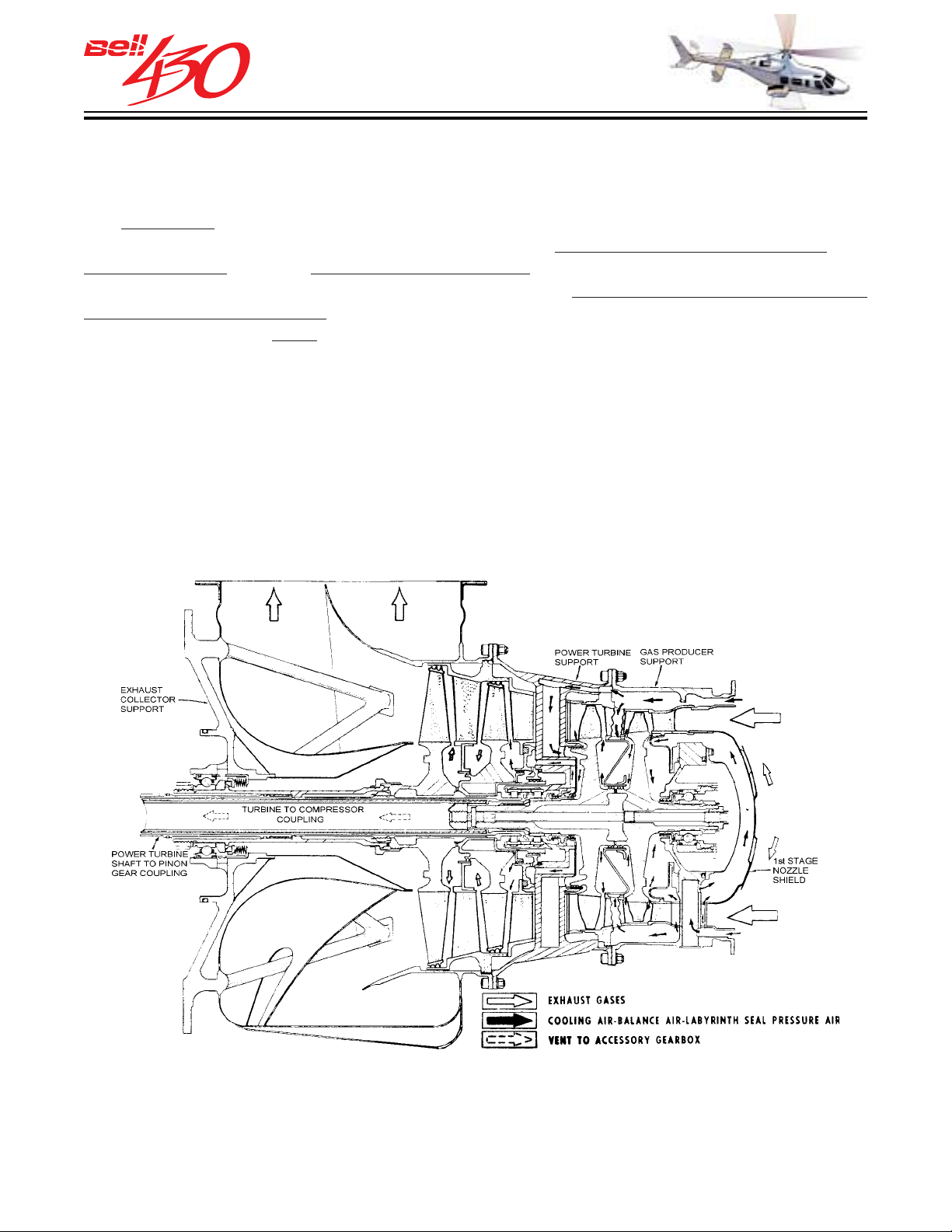
THIS ELECTRONIC DOCUMENT MAY HAVE BEEN SUPERCEDED.
THE MOST CURRENT DOCUMENT INFORMATION IS AVAILABLE
THIS IS AN UNCONTROLLED DOCUMENT.
FROM YOUR BELL HELICOPTER TEXTRON REPRESENTATIVE.
AIR COOLING
Approximately 20% to 25% of the air entering the combustion chamber is required to
burn the fuel, while the remaining air is used for engine cooling and thrust balance.
cooling air is directed into the combustion liner, to prevent the flame from contacting
The
the liner wall, and to cooling air passages in the gas producer turbine support, the
turbine nozzles, and the first stage nozzle shield. Some of the high-pressure cooling
air is delivered to the thrust balance chamber at the forward face of the second stage
gas producer turbine rotor to offset forward pressure from combustion gas flow and
reduce loads on the
No.8 thrust bearing.
TURBINE COOLING & BALANCE AIR SCHEMATIC
PRODUCT DATA JANUARY 2003
94
Page 95
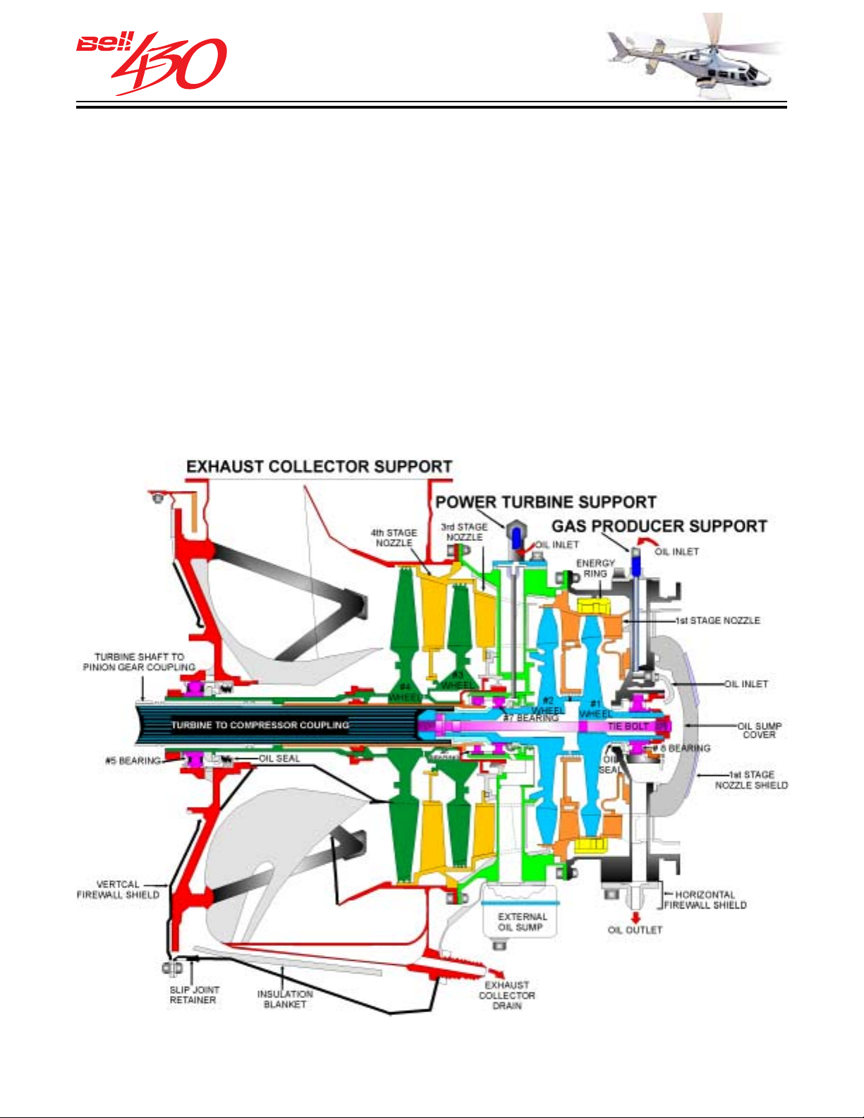
THIS ELECTRONIC DOCUMENT MAY HAVE BEEN SUPERCEDED.
THE MOST CURRENT DOCUMENT INFORMATION IS AVAILABLE
THIS IS AN UNCONTROLLED DOCUMENT.
FROM YOUR BELL HELICOPTER TEXTRON REPRESENTATIVE.
TURBINE SECTION
The turbine section consists of a gas producer turbine support, a power turbine support,
an exhaust collector support, a two-stage gas producer turbine, and a two-stage power
turbine. The gas producer, power turbine, and exhaust collector supports are high
temperature resistant structures which house support and thrust bearings, oil and air
seals, passages for lubrication, cooling air and thrust balance air, temperature sensing
thermocouples, and the outer casings which connect the combustion section and the
accessory gearbox. The two turbine units are free to revolve independently of one
another. Each turbine stage consists of a stator, or nozzle (stationary guide vanes
which direct the combustion gases) and a rotor, or turbine wheel (which is reaction driven by the combustion gases).
TURBINE SECTION SCHEMA T I C
PRODUCT DATA JANUARY 2003
95
Page 96
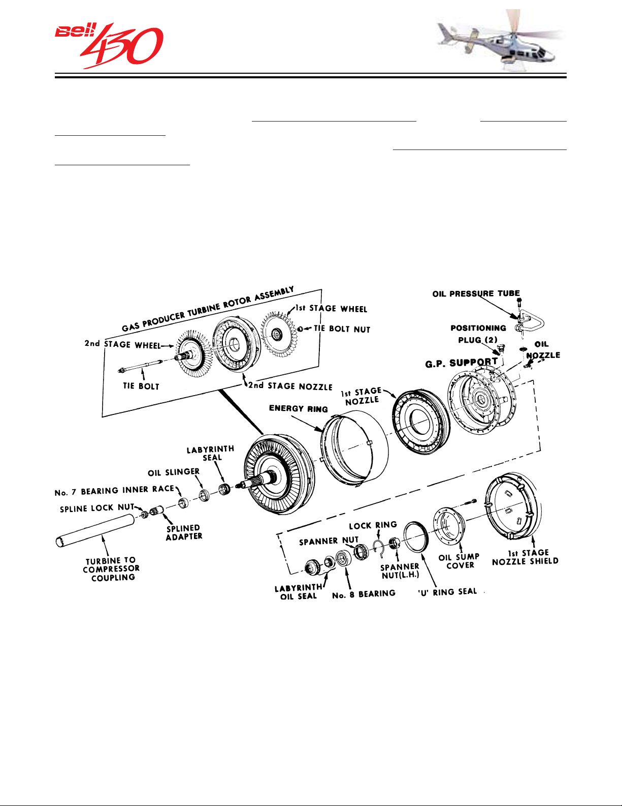
THIS ELECTRONIC DOCUMENT MAY HAVE BEEN SUPERCEDED.
THE MOST CURRENT DOCUMENT INFORMATION IS AVAILABLE
THIS IS AN UNCONTROLLED DOCUMENT.
FROM YOUR BELL HELICOPTER TEXTRON REPRESENTATIVE.
GAS PRODUCER TURBINE (NG)
The first two turbine stages are coupled to the compressor, and also power the gas producer gear train. At 100 % RPM they rotate at 51,000 RPM . The gas producer support contains a protective energy containment ring, which
producer turbine wheel. The energy ring guards against damage from ballistic fragments
in the event of a turbine wheel failure.
surrounds the first stage gas
PRODUCT DATA JANUARY 2003
96
Page 97
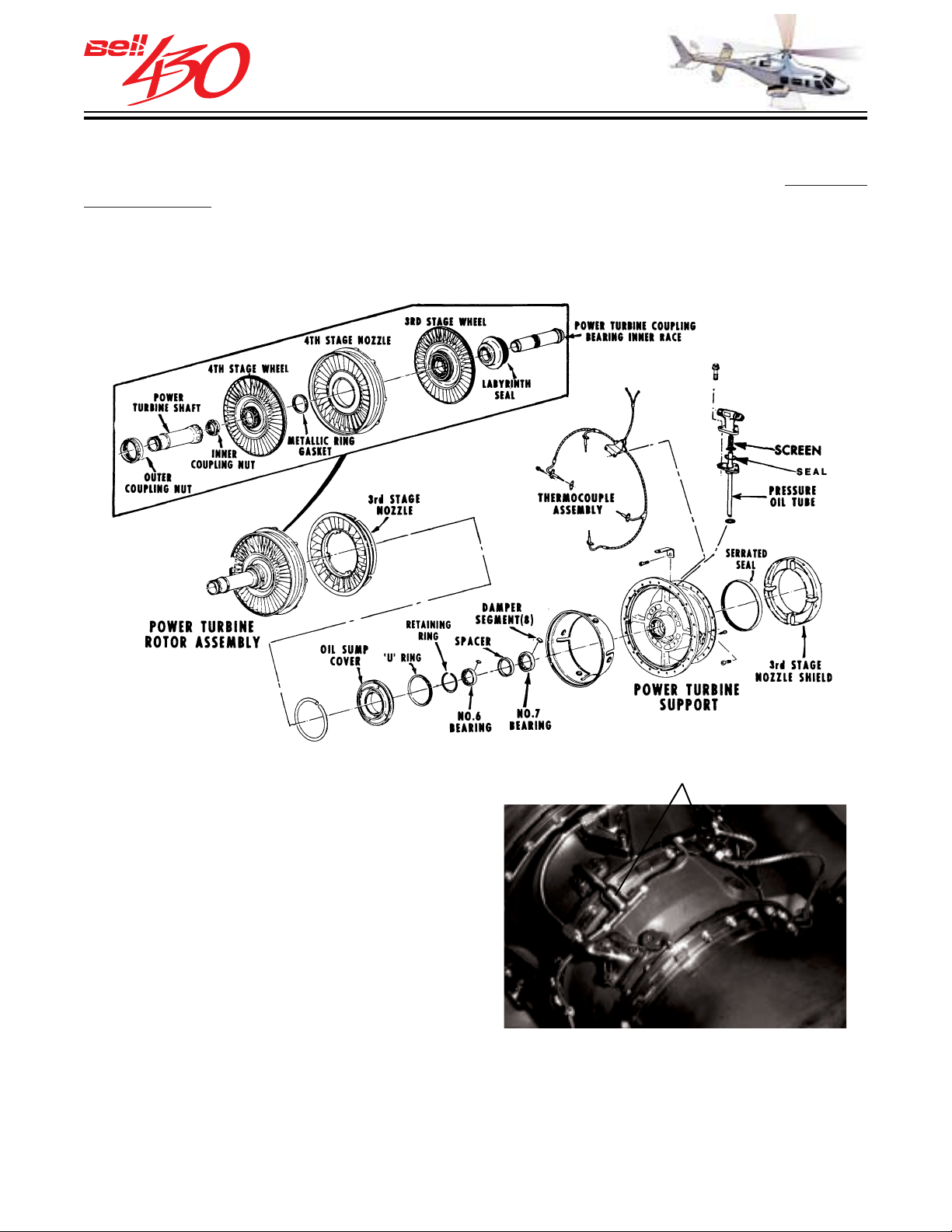
THIS ELECTRONIC DOCUMENT MAY HAVE BEEN SUPERCEDED.
THE MOST CURRENT DOCUMENT INFORMATION IS AVAILABLE
THIS IS AN UNCONTROLLED DOCUMENT.
FROM YOUR BELL HELICOPTER TEXTRON REPRESENTATIVE.
PO WER TURBINE (NP)
The final two turbine stages extract energy from the combustion gases to drive the
power turbine. At 100 % RPM the power turbine rotates at 30,908 RPM.
MGT HARNESS
TEMPERATURE SENSING
The power turbine support incorporates a thermocouple assembly, which senses the
temperature of the combustion gases as they exit the second stage gas producer rotor.
Four ALUMEL-CHROMEL probes generate a DC current directly proportional to the
temperature of the gas. The thermocouple harness averages the four voltages and
transmits the resulting signal to the ARINC-429 databus and IIDS.
PRODUCT DATA JANUARY 2003
97
Page 98
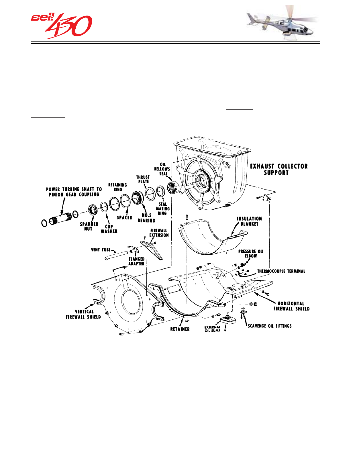
THIS ELECTRONIC DOCUMENT MAY HAVE BEEN SUPERCEDED.
THE MOST CURRENT DOCUMENT INFORMATION IS AVAILABLE
THIS IS AN UNCONTROLLED DOCUMENT.
FROM YOUR BELL HELICOPTER TEXTRON REPRESENTATIVE.
EXHAUST COLLECTOR SECTION
The exhaust collector section is fabricated of high temperature resistant stainless steel formed sheets and castings. The exhaust collector support holds the aft portions of the engine and is attached to the accessory gearbox cover with six studs. The exhaust
collector duct incorporates a center tube and power turbine shaft shield which protects
the power turbine shaft from the exhaust gas. The duct has a single rectangular outlet at its' top, which supports the exhaust ejector stack. The
horizontal firewall shield and insulation blanket protect accessories from radiant heat.
vertical firewall shield and
PRODUCT DATA JANUARY 2003
98
Page 99
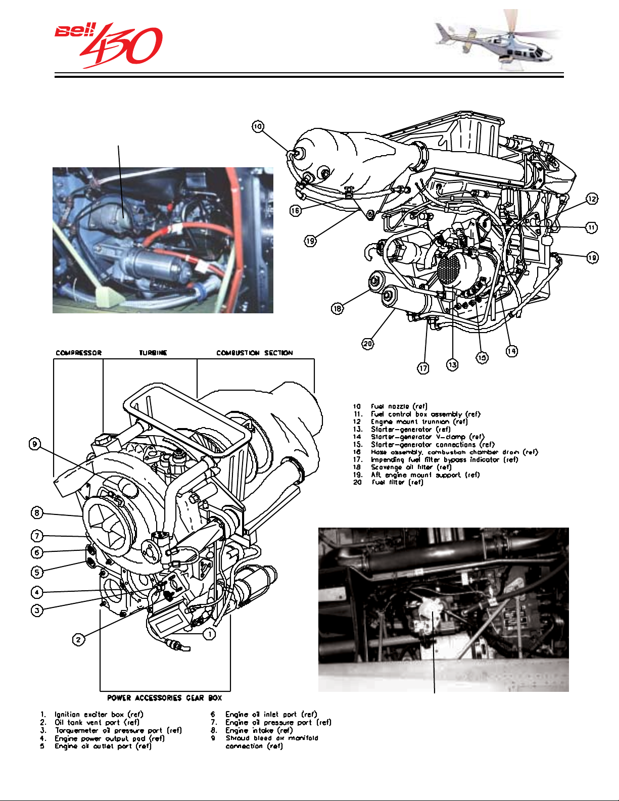
THIS ELECTRONIC DOCUMENT MAY HAVE BEEN SUPERCEDED.
THE MOST CURRENT DOCUMENT INFORMATION IS AVAILABLE
THIS IS AN UNCONTROLLED DOCUMENT.
FROM YOUR BELL HELICOPTER TEXTRON REPRESENTATIVE.
ENGINE ACCESSORIES & CONTROLS
PERMANENT
MAGNET
ALTERNATOR
*
*
*
*
*CEFA (COMBINED ENGINE FILTER ASSEMBLY)
HYDROMECHANICAL UNIT
PRODUCT DATA JANUARY 2003
99
Page 100
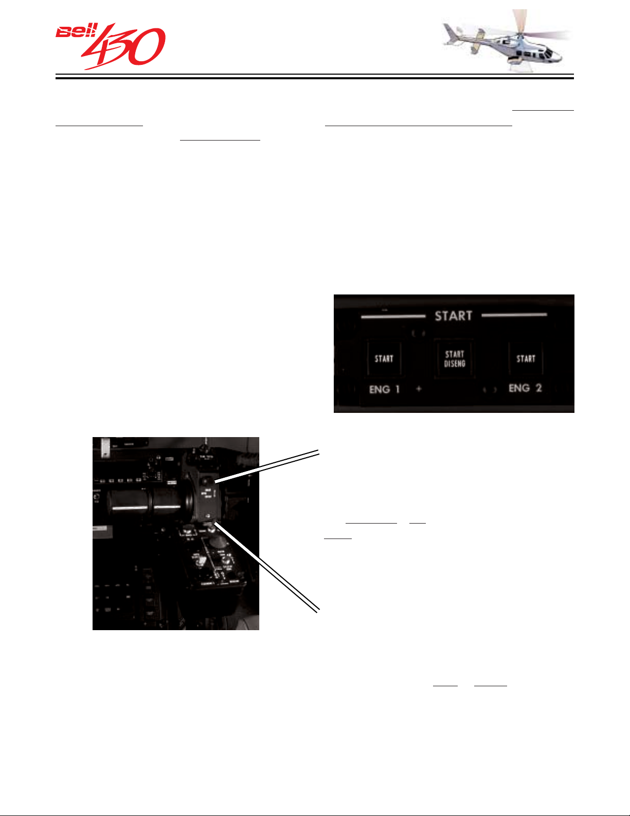
THIS ELECTRONIC DOCUMENT MAY HAVE BEEN SUPERCEDED.
THE MOST CURRENT DOCUMENT INFORMATION IS AVAILABLE
THIS IS AN UNCONTROLLED DOCUMENT.
FROM YOUR BELL HELICOPTER TEXTRON REPRESENTATIVE.
STARTER / GENERATORS
The starter / generators are mounted on the lower right side of each engines
gearbox cover, and drive / are driven by the gas producer turbine gear train . The drive
shaft of each unit is
oil lubricated (wet spline system) and has an engine protective
shear point. Air cooling is accomplished with an integral fan, assisted by dedicated
air inlets on the lower outboard engine cowlings.
accessory
EVENT RECORDING
The IIDS records the occurrence of an engine start in its nonvolatile memory, and if an
exceedance occurs it also records the date/time, duration and magnitude . This allows
maintenance personnel to confirm the helicopter logbook start count totals for transfer
to the individual engine logs cycle record, and insure that any required maintenance
action is performed.
ENGINE ST ART CONTROL PANEL
Engine starting is controlled by three push/
push illuminated switches mounted above
the engine instruments group. When the
START 1 or START 2 switches are
engaged, the starter is continuously
motored until automatic disengagement
occurs at 56% N
DISENG switch is depressed.
or the center START
G
RPM SWITCH
A two-way "BEEP" switch mounted on the
pilots' collective lever provides a signal to
each FADEC ECU for fine adjustment of
. Forward / aft movement adjusts NP of
N
P
both engines up / down.
TEMP/TORQUE MATCHING
A two-way momentary switch mounted on
the collective control box provides a signal
to the IIDS which controls the mode for
engine matching.
of the switch selects either same MGT
mode, or same Q [engine torque] mode.
Left or Right movement
PRODUCT DATA JANUARY 2003
100
 Loading...