


 Loading...
Operating and Maintenance Manual
for the
PortaBELL™ II
Dental Field Treatment and Operating System II
Revision H
December, 2005
Bell Dental Products, LLC
3003 Arapahoe St., 101B
Denver, CO 80205
|
TABLE OF CONTENTS |
|
1.0 INTRODUCTION ........................................................................................................................ |
4 |
|
1.1 |
Safety Precautions ................................................................................................................................. |
4 |
1.2 |
Summary of Key Operation and Maintenance Activities...................................................................... |
5 |
1.3 |
System Description................................................................................................................................ |
6 |
1.4 |
Principles of Operation.......................................................................................................................... |
7 |
1.4.1 Electric Power Subsystem ............................................................................................................ |
17 |
|
1.4.2 Electronic Control Subsystem ...................................................................................................... |
20 |
|
1.4.3 Air Supply Subsystem .................................................................................................................. |
21 |
|
1.4.4 Water Supply Subsystem.............................................................................................................. |
21 |
|
1.4.5 Vacuum Supply Subsystem.......................................................................................................... |
22 |
|
2.0 SET-UP..................................................................................................................................... |
23 |
|
3.0 OPERATION ............................................................................................................................ |
31 |
|
4.0 PACKING THE UNIT FOR SHIPPING AND STORAGE ......................................................... |
34 |
|
5.0 MAINTENANCE ....................................................................................................................... |
40 |
|
5.1 |
Periodic Maintenance .......................................................................................................................... |
40 |
5.2 |
Sterilization and Disinfection .............................................................................................................. |
41 |
5.3 |
Cleaning .............................................................................................................................................. |
41 |
5.3.1 Motor............................................................................................................................................ |
41 |
|
5.3.2 Hand Pieces .................................................................................................................................. |
43 |
|
5.3.3 Waste container and waste container top ..................................................................................... |
45 |
|
5.3.4 Vacuum Hoses.............................................................................................................................. |
45 |
|
5.3.5 Vacuum Water Trap ..................................................................................................................... |
45 |
|
5.3.6 Water Reservoir and Water Lines ................................................................................................ |
45 |
|
5.3.7 Base Unit and Control Panel ........................................................................................................ |
45 |
|
5.3.8 Instrument Tray ............................................................................................................................ |
45 |
|
5.4 |
Draining the Water Traps .................................................................................................................... |
45 |
5.4.1 Draining the Compressor Water Trap .......................................................................................... |
46 |
|
5.4.2 Draining the Vacuum Water Trap ................................................................................................ |
46 |
|
5.5 |
Cleaning or Replacing the Filter Elements.......................................................................................... |
46 |
5.5.1 Replacing the Water Line Filter Element (PN 9100010) ............................................................ |
46 |
|
5.5.2 Replacing the Vacuum Line Water Trap Filter Element (PN 9100258) ..................................... |
47 |
|
5.5.3 Replacing the Compressor Water Trap Filter Element................................................................. |
47 |
|
5.5.4 Replacing the Compressor Inlet Filter Element............................................................................ |
47 |
|
5.5.5 Cleaning the Cooling Air Filter Elements .................................................................................... |
48 |
|
5.5.6 Replacing the Cooling Air Filter Elements .................................................................................. |
48 |
|
5.6 |
Replacing the Fiber Optic Lamp ......................................................................................................... |
49 |
5.7 |
Checking the Suction System.............................................................................................................. |
49 |
5.8 |
Adjustments and Calibration ............................................................................................................... |
50 |
5.8.1 Voltage to the Hand Piece Motor ................................................................................................. |
50 |
|
5.8.2 Motor Speed Indication ................................................................................................................ |
51 |
|
5.8.3 Regulated Pressure ....................................................................................................................... |
53 |
|
5.8.4 Compressor Pressure Relief ......................................................................................................... |
54 |
|
5.8.5 Checking Cooling Air Flow to the Motor .................................................................................... |
54 |
|
5.9 |
Removing and Replacing the Main Circuit Board .............................................................................. |
55 |
5.10 Removing Tubing From Push-in Fittings.......................................................................................... |
56 |
|
6.0 TROUBLESHOOTING ............................................................................................................. |
57 |
|
6.1 |
Motor and Hand Piece......................................................................................................................... |
57 |
6.2 |
Vacuum Supply Subsystem................................................................................................................. |
58 |
6.3 |
Air and Water Supply Subsystems ...................................................................................................... |
59 |
6.4 |
Electronics........................................................................................................................................... |
60 |
7.0 MAJOR SYSTEM COMPONENTS .......................................................................................... |
66 |
|
|
ii |
|
7.1 Water Subsystem Components............................................................................................................ |
66 |
7.2 Major Components - Base Unit........................................................................................................... |
67 |
7.3 Major Components – Top of Unit ....................................................................................................... |
68 |
8.0 WARRANTY ............................................................................................................................. |
69 |
9.0 CUSTOMER SERVICE ............................................................................................................ |
69 |
10.0 SPECIFICATIONS.................................................................................................................. |
70 |
APPENDIX A – System Parts List.................................................................................................. |
71 |
APPENDIX B – Schematics and Parts Lists .................................................................................. |
78 |
Main Circuit Board Schematics................................................................................................................. |
79 |
Main Circuit Board Layout ....................................................................................................................... |
83 |
Main Circuit Board Parts List.................................................................................................................... |
84 |
Keypad Circuit Board LEDs Schematic.................................................................................................... |
86 |
Keypad Circuit Board Buttons Schematic................................................................................................. |
87 |
Keypad Circuit Board Parts List................................................................................................................ |
88 |
Voltage Control Circuit Board Schematic................................................................................................. |
89 |
Voltage Control Circuit Board Layout ...................................................................................................... |
90 |
Voltage Control Circuit Board Parts List .................................................................................................. |
91 |
APPENDIX C - Main Circuit Board Connector Test Point Values.................................................. |
92 |
APPENDIX D - BIEN AIR ELECTRIC HANDPIECE MAINTENANCE........................................... |
94 |
APPENDIX E - Sterilization and Maintenance Instructions For Motor and Hand Pieces .............. |
95 |
APPENDIX F – Acceptance Test Record....................................................................................... |
97 |
iii
1.0 INTRODUCTION
This Operating and Maintenance Manual describes the set-up, operation, maintenance, and troubleshooting of the PortaBELL™ II Dental Field Treatment and Operating System (DeFTOS).
NOTE
The PortaBELL™ II is a prescription device. Federal law restricts the sale to or on the order of a dentist.
1.1 Safety Precautions
Only personnel who have completed a course in the operation and maintenance of this equipment are authorized to set-up, operate, maintain, and repair the equipment. All personnel should carefully review this manual before performing any operation. A list of safety precautions is presented in Table 1.1-
1.
Table 1.1-1
Safety Precautions
What to Look For |
Safety Concern |
What To Do |
Hot parts |
The vacuum pump and compressor |
Do not touch the vacuum pump or compressor. |
|
heads and motor can become hot |
Allow unit to cool at least 60 minutes, with |
|
when operated for an extended time. |
cooling fan running, before performing service. |
Electricity |
Electric shock |
Never use the system directly in rain or wet |
|
|
conditions. |
|
|
Always unplug the system before performing |
|
|
any maintenance or repair. |
|
|
Verify the system is properly grounded. |
|
|
Make sure the frequency of the load connected |
|
|
to the duplex outlet and the mains power are |
|
|
the same |
Flammable vapors |
As with an air compressor for an air |
Use only in well ventilated areas |
|
driven system, operation of the system |
|
|
in the presence of flammable vapors |
|
|
can create a fire or explosion hazard. |
|
Fire |
The frequency of any load connected |
Make sure the frequency of the load connected |
|
to the duplex outlet must match the |
to the duplex outlet and the mains power are |
|
mains frequency. If they are different it |
the same |
|
may cause the load and/or step down |
|
|
transformer to over heat. |
|
© 2004 Bell Dental Products, LLC. All rights reserved. No portion may be copied or reproduced without express written permission from Bell Dental Products, LLC.
4
1.2 Summary of Key Operation and Maintenance Activities
This section presents the key points that a DeFTOS operator and supporter should be aware of.
The motor will go to full speed when the Panel/Foot Switch control is switched to foot switch if the foot switch is not connected.
The compressor/vacuum pump may not restart if there is a vacuum on the vacuum line, make sure the waste container is connected to the system.
DO NOT autoclave the motor.
If a sudden loss of vacuum is experienced it is probably caused by a full waste container.
If there is low suction it is probably caused by a leak or loose connection.
Check filters and water traps at the end of each day.
If the hand piece leaks from the motor, tighten the hose connection at the base of the motor, hand tighten only, DO NOT use any tool.
If the hand piece leaks from the interface with the motor, replace the motor o-rings.
Take care to connect the motor hose to the motor, the threads are very fine and easy to cross thread.
Take care when connecting the motor tubing to the base unit, the locking collar locks with only a 1/16 turn click.
Take care when connecting the foot switch to the base unit, the locking collar locks with only ¼ turn.
Take care when removing the main circuit board to avoid damage to the control panel label. The control panel label is “taped” to the button control circuit board with an adhesive. The button control circuit board is connected to the main circuit board via 2 connectors. Carefully unplug the main circuit board from the button circuit board to avoid damaging the label.
If the 3-way syringe does not work, check the installation of the valve in the handle, make sure it is fully inserted into the handle and locked with a twist.
The compressor bleed valve will make a hissing noise immediately after the compressor is turned OFF.
© 2004 Bell Dental Products, LLC. All rights reserved. No portion may be copied or reproduced without express written permission from Bell Dental Products, LLC.
5
Make sure the frequency of any load connected to the duplex outlet is the SAME AS the main power frequency.
The power rating of the duplex outlet is 100VA.
The hand piece motor will get warm if the fiber optics is used continuously because the fiber optic bulb is mounted in the motor housing.
The hand piece motor requires cooling air. Motor damage may result if the motor is operated for extended periods without cooling airflow. If cooling air to the motor is lost the Low Cooling Air To Motor LED will come on and the motor will stop. To restart the motor, press the speed increase button.
If the vacuum pump is left ON continuously the controller will turn it OFF if there is NO activity of the hand piece motor for approximately 12 minutes. It will then blink the Compressor ON and Vacuum Pump ON LEDs to indicate that the vacuum pump has been turned OFF. To restart normal operation press any button on the control panel.
It is possible for the vacuum shut-off valve in the waste container to activate prematurely and/or stick if it has not been cleaned completely. To restore flow If the valve activates prematurely you must release the vacuum on the valve. To release the vacuum just turn the vacuum pump OFF and open the HVE valve, this will allow the valve to OPEN.
1.3 System Description
The PortaBELL™ II DeFTOS is a state-of-the-art system utilizing the latest electric motor driven hand piece technology to meet the demanding needs of the modern mobile dentist.
The system incorporates all of the functionality to perform any dental procedure from cleaning to oral surgery. The system includes an electric motor, with or without fiber optics, high speed hand piece, low speed hand piece, air/water supply, air/water syringe, high volume evacuator (HVE), saliva ejector, and variable speed foot switch. In addition an optional FDA cleared scalar and curing light are available.
The system is lightweight and totally self-contained. The system includes an oilless air compressor and vacuum pump that provides air to the water and air supply subsystems and suction for the saliva ejector and HVE, a self-contained water supply for hand piece coolant and oral irrigation, and a waste container for collection of liquids and solids from the HVE and saliva ejector. The system supports a variety of standard electric motors and all E-type connected hand pieces.
© 2004 Bell Dental Products, LLC. All rights reserved. No portion may be copied or reproduced without express written permission from Bell Dental Products, LLC.
6
The system will operate on any power from 100VAC to 240VAC, 50 or 60 Hz without the need for a transformer.
The entire system can be quickly assembled or disassembled and packs into one molded shipping and storage container for safe transport and storage.
The system components are shown and identified in Figures 1.3-1 and 1.3-2.
1.4 Principles of Operation
The system is composed of an electric power subsystem, an electronic control subsystem, a compressed air subsystem, a water subsystem, and a vacuum subsystem. Each is described below.
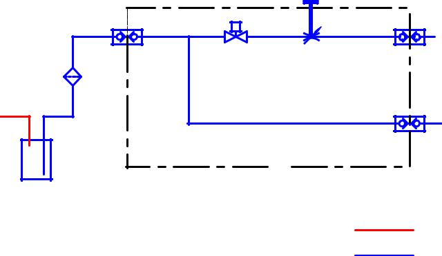
The principle of operation is simple, refer to Figures 1.4-1 through 1.4-5, the compressor pressurizes the air storage tank. Compressed air is provided to the motor for cooling, the hand piece for chip air, the air/water syringe, and the water reservoir, refer to Figure 1.4-1. Water is forced from the water reservoir by the compressed air and flows to the hand piece and air/water syringe. Flow of the water and air to the motor and hand piece is controlled by solenoid valves and adjusted by needle valves, refer to Figures 1.4-1 and 1.4-2. Vacuum is provided by the vacuum pump. The vacuum pump is connected to the waste container. The waste container is connected to the HVE and saliva ejector, refer to Figure 1.4-3. Operation of the unit is controlled from the control panel. A description of the controls and connections is presented in Tables 1.4-1 and 1.4-
2.
© 2004 Bell Dental Products, LLC. All rights reserved. No portion may be copied or reproduced without express written permission from Bell Dental Products, LLC.
7
TABLE 1.4-1
DESCRIPTION OF THE CONTROL PANEL CONTROLS
(REFER TO FIGURE 1.4-4)
CONTROL |
DESCRIPTION |
HAND PIECE WATER FLOW ADJUST |
Adjusts the flow of cooling water to the hand piece |
HAND PIECE WATER ON/OFF |
Turns power ON and OFF to the water solenoid |
HAND PIECE AIR FLOW ADJUST |
Adjusts the flow of chip air to the hand piece |
HAND PIECE AIR ON/OFF |
Turns power ON and OFF to the air solenoid |
PANEL/FOOT SWITCH CONTROL |
Switches operating mode for controlling motor speed |
|
between the foot switch and the control panel |
COMPRESSOR ON/OFF |
Turns power ON and OFF to the compressor |
FIBER OPTICS ON/OFF |
Turns power ON and OFF to the fiber optics |
FIBER OPTIC INTENSITY |
Control to adjust the intensity of the fiber optic light |
MOTOR ON/OFF |
Turns power ON and OFF to the motor |
VACUUM ON/OFF |
Turns power ON and OFF to the vacuum pump |
MOTOR SPEED |
Controls motor speed when in the PANEL operating |
|
mode |
LOW AIRFLOW TO MOTOR |
Indicates when there is low cooling airflow to the motor |
POWER ON |
Indicates when the main power is ON |
MOTOR SPEED |
Bar graph type indicator of the motor speed. 4 scales |
|
are presented, one for each of 4 different hand piece |
|
ratios; 1:5, 1:1, 2.7:1 and 10:1. Read the appropriate |
|
scale for the hand piece being used. |
© 2004 Bell Dental Products, LLC. All rights reserved. No portion may be copied or reproduced without express written permission from Bell Dental Products, LLC.
8
TABLE 1.4-2
DESCRIPTION OF BACK PANEL (REFER TO FIGURE 1.4-5)
CONNECTION |
DESCRIPTION |
AUXILLIARY AIR INLET |
Provides means to charge the air storage tank with |
|
compressed air from an external source |
AIR STORAGE TANK |
Connection for hose to air storage tank |
MOTOR/HAND PIECE |
Integrated connector for the motor power, fiber |
|
optics power, motor cooling air, hand piece cooling |
SYRINGE |
water, and hand piece chip air |
|
|
AIR |
Connection for air line for air/water syringe |
WATER |
Connection for water line for air/water syringe |
WATER IN |
Connection for water from the water reservoir |
AIR OUT |
Connection for compressed air out to the water |
|
reservoir |
COVER LATCH |
Latches the top in place |
VACUUM OUT |
Connection for vacuum line to the waste container |
FOOT SWITCH |
Connector for the foot switch cable |
AC RECEPTACLE CIRCUIT |
Circuit breakers for both legs of power to the Duplex |
BREAKERS |
Outlet |
AC RECEPTACLE |
Duplex Outlet, 120 VAC 50/60 HZ, 100 watts max. |
|
Frequency will be the same as the mains power. |
|
Outlets are switched with main power switch and |
|
both legs are protected with circuit breaker |
MAINS CIRCUIT BREAKERS |
Circuit breakers for both legs of mains power |
POWER SWITCH AND |
Switches main power ON and OFF and connection |
POWER CORD CONNECTOR |
for power cord |
© 2004 Bell Dental Products, LLC. All rights reserved. No portion may be copied or reproduced without express written permission from Bell Dental Products, LLC.
9

Figure 1.3-1
Extension arms
PN 9100223
Support Pole Brackets
PN 9100377
Water bottle
PN 9100080
PortaBELL™II DeFTOS II Major Components |
Shipping and storage container |
|
PN 9100259 |
|
|
Waste container assembly
PN 4202049
Hand piece lubricant and cleaner
PN 9400082 and 9400081 respectively
|
|
Hose and motor storage pouches |
Instrument tray support pole |
|
|
|
PN 9100087 and 9100088 |
|
PN 9100222 |
|
|
|
|
Vacuum to base hose assembly
PN 4202005 Base unit PN 4201002
Motor tubing
PN 9100286
Air storage tank assembly Instrument tray assembly PN 4201003
PN 4202041
Saliva ejector hose assembly Motor and hand piece  PN 4202008
PN 9400022
HVE hose assembly Water manifold assembly PN 4202007
PN 4202013
Foot switch Air water syringe PN 9400051
PN 4202004
Air storage tank hose assembly Power cord PN 4202001
PN 9100086
© 2004 Bell Dental Products, LLC. All rights reserved. No portion may be copied or reproduced without express written permission from Bell Dental Products, LLC.
10
Figure 1.3-2
PortaBELL™II DeFTOS II Accessory Support Components
|
|
Water Filter Element |
|
|
|
|
|
|
(PN9100010) |
|
|
Compressor Inlet |
|
|
|
|
|
|
||
|
|
|
|
|
Filter Element |
|
|
|
|
|
|
(PN9100350) |
|
|
|
|
|
|
|
|
|
|
|
|
|
|
|
HVE brush |
|
|
|
|
Side Air Filter |
|
(PN9100253) and Tip |
|
|
|
|
Element |
|
(PN9100353) |
|
|
|
|
(PN9100473) |
|
|
|
|
|
|
|
|
|
|
|
|
|
|
|
Motor Tip O-rings (PN9100294)
Fiber Optic Bulb (PN9100207)
Saliva Ejector Brush
(PN9100252) and Tip (PN9100357)
|
|
Hand Piece Orifice |
Ground Cable Assembly |
|
|
|
Cleaning Tool |
|
PN9400230 |
|
|
|
(PN9100279) |
|
|
|
|
|
|
|
© 2004 Bell Dental Products, LLC. All rights reserved. No portion may be copied or reproduced without express written permission from Bell Dental Products, LLC.
11

Figure 1.4-1
Air Supply Subsystem Block Diagram
|
|
|
|
Air Storage Tank |
|
|
|
|
|
Enclosure |
Quick |
|
|
|
|
|
|
|
|
disconnect |
QD1 |
|
|
|
Quick |
|
|
|
valve |
'A' |
|
|
|||
|
|
|
|
|
||||
|
|
|
|
To VACUUM |
disconnect |
QD3 |
||
|
|
|
|
|
valve |
|||
|
|
|
|
|
|
|
||
|
|
|
|
|
|
|
|
|
|
M1 |
V1 |
|
V2 |
Manifold |
|
'B' |
|
|
Compressor |
R1 |
|
To HYDRO |
||||
|
|
Valve |
Valve |
|
|
|
|
|
Pressure |
|
(1 way) |
Regulator |
(1 way) |
|
|
|
|
|
|
|
|
|
|
|
|
|
Relief |
|
|
|
|
|
|
|
|
Valve |
F1 |
|
|
|
|
|
|
|
|
|
|
Electrical |
solenoid |
|
|||
|
|
|
|
|
||||
|
Filter (5micron) |
|
Printed |
EV1 |
|
valves |
EV2 |
|
|
|
|
|
|
|
|
||
|
with water trap |
|
Wiring Board |
|
|
|
V4 |
|
|
|
|
|
|
|
|
|
|
|
|
|
|
Quick |
|
Needle |
|
|
|
|
|
|
|
valve |
|
||
|
|
|
|
disconnect |
|
|
||
|
|
|
|
|
|
|
||
|
|
|
|
valves |
|
|
|
|
|
|
V3 |
G1 |
QD5 |
(3) |
QD4 |
QD6 |
|
|
|
Tire |
Pressure |
|
|
|||
|
|
|
|
|
|
|
||
|
|
valve |
Guage |
To |
To |
To |
|
|
|
|
|
|
|
||||
|
|
|
|
Motor |
Air/Water |
Handpiece |
|
|
|
|
|
|
|
syringe |
|
|
|
© 2004 Bell Dental Products, LLC. All rights reserved. No portion may be copied or reproduced without express written permission from Bell Dental Products, LLC.
12
'B' From PNEUMATICS
Figure 1.4-2
Water Supply Subsystem Block Diagram
Quick disconnect valve
QD7
F3
Filter
W2
Water reservoir
|
|
QD8 |
To |
|
|
|
|
EV3 |
V5 |
|
Handpiece |
|
|
||
Electrical |
Quick |
|
|
Needle |
|
||
solenoid |
valve |
disconnect |
|
valve |
|
valves |
|
|
|
|
To |
|
|
|
Air/Water |
|
|
QD9 |
syringe |
|
|
|
|
Enclosure |
|
|
|
Pressurized air
Pressurized Water
© 2004 Bell Dental Products, LLC. All rights reserved. No portion may be copied or reproduced without express written permission from Bell Dental Products, LLC.
13
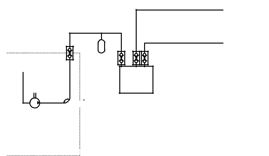
Figure 1.4-3
Vacuum Supply Subsystem Block Diagram
Exhaust |
|
|
|
V6 |
|
|
|
|
|
|
|
|
|
High Volume |
|
W3 |
|
|
Evacuation |
|
|
|
(HVE) Valve |
|
|
Fluid |
|
|
|
|
|
|
|
|
|
trap |
|
|
|
Quick |
|
|
|
V7 |
disconnect |
|
|
||
|
|
Saliva |
||
valves |
|
QD12 |
|
|
|
Quick |
ejector |
||
|
QD11 |
QD13 |
Valve |
|
|
disconnect |
|
||
QD10 |
QD2 |
|
valves |
|
Exhaust |
|
W4 |
(3) |
|
|
|
|
|
|
|
|
Waste |
|
|
M2 |
|
container |
|
|
|
(0.5 L) |
|
Vacuum |
|
Vacuum |
|
|
||
Pump |
|
|
|
|
|
MV1 |
|
|
Pressurized air |
|
|
|
|
|
|
Manual |
|
|
|
|
Ball Valve |
|
|
|
'A' From PNEUMATICS
Enclosure 
© 2004 Bell Dental Products, LLC. All rights reserved. No portion may be copied or reproduced without express written permission from Bell Dental Products, LLC.
14
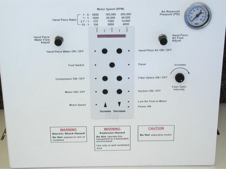
Figure 1.4-4
Control Panel
© 2004 Bell Dental Products, LLC. All rights reserved. No portion may be copied or reproduced without express written permission from Bell Dental Products, LLC.
15
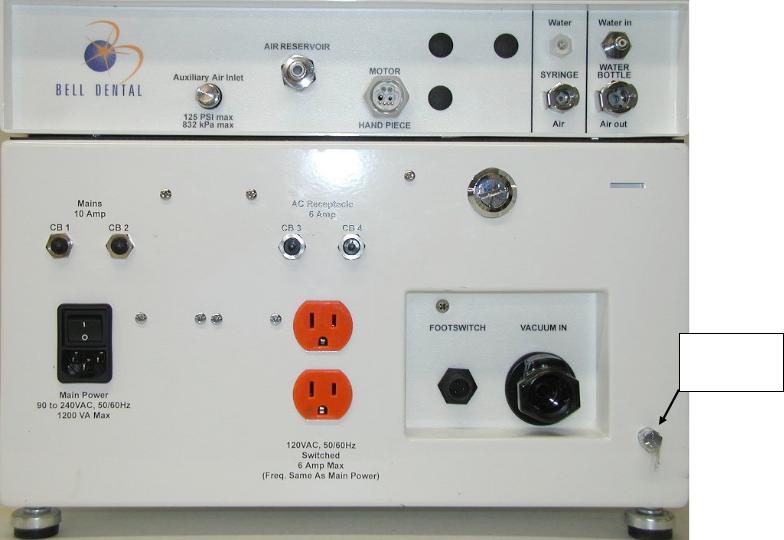
Figure 1.4-5
Back Panel
External
Ground
Connection
© 2004 Bell Dental Products, LLC. All rights reserved. No portion may be copied or reproduced without express written permission from Bell Dental Products, LLC.
16
1.4.1 Electric Power Subsystem
The electric power subsystem provides power to the unit. It is composed of the power cord, power cord connector, main power switch, duplex outlet, circuit breakers, RF Filter, compressor/vacuum pump relay, power supply, voltage control circuit board, voltage control relays, 220VAC to 110VAC step down transformer, and associated connections and wiring, refer to Figures 1.4-6 and 1.4-7.
The system is designed to be capable of operation on any power from
100VAC to 240VAC, 50 or 60 Hz. The voltage control circuit board senses the input voltage and configures the power system according to the power it is connected to. The voltage control circuit board senses the voltage and then configures the voltage control relays to the proper configuration.
The duplex outlet allows for the connection and operation of additional accessories. It is switched through the power switch and has its own circuit breakers. It is connected to a step-down transformer for when the unit is connected to 200VAC or more.
NOTE
The duplex outlet will ALWAYS be approximately 110VAC. The voltage will vary depending on the mains voltage. The frequency will be THE SAME AS the mains power.
WARNING - Electrical and Fire hazard
If the frequency of the load and the duplex outlet are not the same it may cause heating of the load and step down transformer and may cause an electrical short or fire.
NOTE
The duplex outlet is rated for 100watts
The entire unit is protected by a 10-amp circuit breaker incorporated into the mains power circuit and the line and return of the duplex outlet are protected by 2A circuit breakers.
© 2004 Bell Dental Products, LLC. All rights reserved. No portion may be copied or reproduced without express written permission from Bell Dental Products, LLC.
17
Figure 1.4-6
Electric Power Block Diagram
© 2004 Bell Dental Products, LLC. All rights reserved. No portion may be copied or reproduced without express written permission from Bell Dental Products, LLC.
18
Figure 1.4-7
Circuit Board Block Diagram
Handpiece |
|
|
|
|
|
|
|
|
|
|
|
|
|
|
|
|
|
|
|
|
|
|
|
|
|
|
|
|
|
|
|
|
|
|
|
|
|
|
|
|
|
|
||||
|
|
Air |
Motor Air |
|
Water |
|
|
|
|
|
|
|
|
|
|
|
|
|
|
|
|
|
|
|
|
|
||||||||||||||||||||
|
Sol. |
|
Sol. |
|
Sol. |
|
|
Control |
|
|
|
|
|
|
|
|
|
|
|
|
|
|||||||||||||||||||||||||
|
|
|
|
|
|
|
|
|
|
|
|
|
|
|
|
|
|
|
|
|
|
|
|
|
|
|
|
|
|
|
|
|
|
|
|
|
|
|
|
|||||||
|
|
|
|
|
|
|
|
|
|
|
|
|
|
|
|
|
|
|
|
|
|
|
|
|
|
|
|
|
|
|
|
|
|
|
|
|||||||||||
|
|
|
|
|
|
|
|
|
|
|
|
|
|
|
Blk |
|
|
|
Panel |
|
|
|
|
Fan |
|
|
|
|
|
|||||||||||||||||
|
|
|
|
|
|
|
|
|
|
|
|
|
|
|
|
|
|
|
||||||||||||||||||||||||||||
|
|
|
|
|
|
|
|
|
|
|
|
|
Wht |
|
|
|
|
|
|
|
|
|
|
|
|
|
|
|
|
|
|
|
|
|
|
|
|
|
||||||||
|
|
|
|
|
|
|
|
|
Blk |
|
|
|
|
|
|
|
|
|
|
|
|
|
|
|
|
|
|
|
|
|
|
|
|
|
|
|
|
|
|
|
|
|
|
|||
|
|
|
|
|
|
|
Wht |
|
|
|
|
|
|
|
|
|
|
|
|
|
|
|
|
|
|
|
|
|
|
|
|
|
|
|
|
|
|
|
|
|
|
|
|
|
||
|
|
|
|
Blk |
|
|
|
|
|
|
|
|
|
|
|
|
|
|
|
|
|
|
|
|
|
|
|
|
|
|
|
|
|
|
|
|
|
|
|
|
|
|
|
|
|
|
|
|
Wht |
|
|
|
|
|
|
|
|
|
|
|
|
|
|
|
|
|
|
|
|
|
|
|
|
|
|
|
|
|
|
|
|
|
|
|
|
|
|
|
|
|
|
||
|
|
|
|
|
|
|
|
|
|
|
|
|
|
|
|
|
|
|
|
|
|
|
|
|
|
|
|
|
|
|
|
|
|
|
|
|
|
Red |
|
|
|
|
|
|
|
|
|
|
|
|
|
|
|
|
|
|
|
|
|
|
|
|
|
|
|
|
|
|
|
|
|
|
|
|
|
|
|
|
|
|
|
|
|
|
|
|
|
|
|
|
|
|
|
|
|
|
|
|
|
|
|
|
|
|
|
|
|
|
|
|
|
|
|
|
|
|
|
|
|
|
|
|
|
|
|
|
|
|
|
|
|
|
|
|
|
|
|
|
|
|
|
|
|
|
|
|
|
|
|
|
|
|
|
|
|
|
|
|
|
|
|
|
|
|
|
|
|
|
|
|
|
|
|
|
|
|
|
|
Blk |
|
|
|
|
|
|
|
|
|
|
|
|
|
|
|
|
|
|
|
|
|
|
|
|
|
|
|
J3 |
|
|
|
|
|
J8 |
|
|
|
|
|
|
|
|
Comp/VAC |
|
To |
||||||||||
|
|
|
|
|
|
|
|
|
|
|
|
|
|
|
|
|
|
|
|
|
|
|
|
|
|
|
|
|
|
|
|
|
||||||||||||||
|
|
|
|
|
|
|
|
|
|
|
|
|
|
|
|
|
|
|
|
|
|
|
|
|
|
|
|
|
|
|
|
|
|
|
|
|
|
|
|
|
|
|||||
|
|
|
|
|
|
|
|
|
|
|
|
|
|
|
|
|
|
|
|
|
|
|
|
|
|
|
|
|
|
|
|
|
|
|
|
|
|
Orn |
|
|
|
|
Relay |
Compress |
||
|
|
|
|
|
|
|
|
|
|
|
|
|
|
|
|
|
|
|
|
|
|
|
|
|
|
|
|
|
|
|
|
|
|
|
|
|
|
Pur |
|
|
|
|
|
|
|
|
|
|
|
|
|
|
|
|
|
|
|
|
|
|
|
|
|
|
|
|
|
|
|
|
|
Circuit |
|
|
|
|
|
|
|
|
|
|
Red |
|
|
|
|
|
|
Foot |
|||
|
|
|
|
|
|
|
|
|
|
|
|
|
|
|
|
|
|
|
|
|
|
|
|
|
|
|
|
|
|
|
|
|
|
|
|
|
|
|
|
|
||||||
|
|
|
|
|
|
|
|
|
|
|
|
|
|
|
|
|
|
|
|
|
|
|
|
|
|
|
|
|
|
|
|
|
|
|
|
|
|
|
|
|||||||
|
|
|
|
|
|
|
|
|
|
|
|
|
|
|
|
|
|
|
|
|
|
|
|
|
|
Board |
|
|
|
|
|
|
|
|
|
|
Grn |
|
|
|
|
|
|
|||
|
|
|
|
|
|
|
|
|
|
|
|
|
|
|
|
|
|
|
|
|
|
|
|
|
|
|
|
|
|
|
|
|
|
|
|
Blk |
|
|
|
|
|
|
Switch |
|||
|
|
|
|
|
|
|
|
|
|
|
|
|
|
|
|
|
|
|
|
|
|
|
|
|
|
|
|
|
|
|
|
|
|
|
|
|
|
|
|
|
|
|
|
|||
|
|
|
|
|
|
|
|
|
|
|
|
|
|
|
|
|
|
|
|
|
|
|
|
|
|
|
|
|
|
|
|
|
J9 |
|
|
|
Blu |
|
|
|
|
|
|
Fiber |
||
|
|
|
|
|
|
|
|
|
|
|
|
|
|
|
|
|
|
|
|
|
|
|
|
|
|
|
|
|
|
|
|
|
|
|
|
|
|
|
|
|
|
|||||
|
|
|
|
|
|
|
|
|
|
|
|
|
|
|
|
|
|
|
|
|
|
|
|
|
|
|
|
|
|
|
|
|
|
|
|
|
|
|
|
|
|
|
|
|||
|
|
|
|
|
|
|
|
|
|
|
|
|
|
|
|
|
|
|
|
|
|
|
|
|
|
|
|
|
|
|
|
|
|
|
|
|
|
Brn |
|
|
|
|
|
|
Optics |
|
|
|
|
|
|
|
|
|
|
|
|
|
|
|
|
|
|
|
|
|
|
|
|
|
|
|
|
|
|
|
|
|
|
|
|
|
|
|
Red |
|
|
|
|
|
|
||
|
|
|
|
|
|
|
|
|
|
|
|
|
|
|
|
|
|
|
|
|
|
|
|
|
|
|
|
|
|
|
|
|
|
|
|
|
|
Blk |
|
|
|
|
|
|
|
|
|
|
|
|
|
|
|
|
|
|
|
|
|
|
|
|
|
|
|
J4 |
|
|
|
J7 |
|
|
|
|
|
|
|
|
|
|
Motor |
||||||||||||
|
|
|
|
|
|
|
|
|
|
|
|
|
|
|
|
|
|
|
|
|
|
|
|
|
|
|
|
|
|
|||||||||||||||||
|
|
|
|
|
|
|
|
|
|
|
|
|
|
|
|
|
|
|
|
|
|
|
|
|
|
|
|
|
|
|
|
|
|
|
|
|
|
|
|
|
|
|
|
|
||
|
|
|
|
|
|
|
|
|
|
|
|
|
|
|
|
|
|
|
|
|
|
|
|
|
|
|
|
|
|
|
|
|
|
|
|
|
|
|
|
|
|
|
|
|
|
|
|
|
|
|
|
|
|
|
|
|
|
|
|
|
|
|
|
|
|
|
|
|
|
|
|
|
|
|
|
|
|
|
|
|
|
|
|
|
|
|
|
|
|
|
|
|
|
|
|
|
|
|
|
|
|
|
|
|
|
|
|
Red |
|
|
|
|
|
|
|
|
|
|
|
|
|
|
|
|
|
|
|
|
|
|
|
|
|
|
|
|
||||
|
|
|
|
|
|
|
|
|
|
From |
|
Blk |
|
|
|
|
|
|
|
|
|
|
|
|
|
|
|
|
|
|
|
|
|
|
|
|
|
|
|
|||||||
|
|
|
|
|
|
|
|
|
|
|
Brn |
|
|
|
|
|
|
|
|
|
|
|
|
|
|
|
|
|
|
|
|
|
|
|
|
|
|
|||||||||
|
|
|
|
|
|
|
|
|
|
|
Blu |
|
|
|
|
|
|
|
|
|
|
|
|
|
|
|
|
|
|
|
|
|
|
|
|
|
||||||||||
|
|
|
|
|
|
|
|
|
|
Power |
|
Orn |
|
|
|
|
|
|
|
|
|
|
|
|
|
|
|
|
|
|
|
|
|
|
|
|
||||||||||
|
|
|
|
|
|
|
|
|
|
|
Pur |
|
|
|
|
|
|
|
|
|
|
|
|
|
|
|
|
|
|
|
|
|
|
|
|
|
||||||||||
|
|
|
|
|
|
|
|
|
|
Supply |
|
|
|
|
|
|
|
|
FO |
|
|
|
|
|
|
|
|
|||||||||||||||||||
|
|
|
|
|
|
|
|
|
|
|
Wht |
|
|
|
|
|
|
|
|
|
|
|
|
|
|
|||||||||||||||||||||
|
|
|
|
|
|
|
|
|
|
|
Grn |
|
|
|
|
|
|
|
|
|
|
|
|
|
||||||||||||||||||||||
|
|
|
|
|
|
|
|
|
|
|
|
|
|
|
|
|
Intensity |
|
|
|
|
|
|
|
|
|||||||||||||||||||||
|
|
|
|
|
|
|
|
|
|
|
|
|
|
|
|
|
|
|
|
|
|
|
|
|
|
|
|
|
|
|
|
|
|
|
|
|
||||||||||
|
|
|
|
|
|
|
|
|
|
|
|
|
|
|
|
|
|
|
|
|
|
|
|
|
|
|
|
|
|
Adj. |
|
|
|
|
|
|
|
|
||||||||
© 2004 Bell Dental Products, LLC. All rights reserved. No portion may be copied or reproduced without express written permission from Bell Dental Products, LLC. 19
Electric power is provided to the compressor/vacuum pump through a logic activated relay. When the control button on the control panel is activated the relay closes and power is provided to the compressor/vacuum pump. The compressor also has a pressure limit shut-off. When the pressure in the air storage tank reaches approximately 60 PSI the control circuit board deactivates the relay turning the compressor/vacuum pump OFF. This also deactivates the normally open bleed solenoid valve bleeding the air from the compressor cylinder.
NOTE
The compressor will not restart with pressure in the compressor cylinder or vacuum in the vacuum line.
1.4.2 Electronic Control Subsystem
The electronic control subsystem powers and controls operation of the low voltage components, hand piece motor, fiber optics, cooling fan, relays, and solenoid valves, refer to Figure 1.4-7. It is composed of the control circuit board and control panel.
The control circuit board takes 36 VDC, 12 VDC, and 5 VDC from the power supply and provides 0 to 30 VDC to the motor, 12 VDC to the solenoid valves, compressor/vacuum pump relay, and fan, and 5 VDC to the fiber optics.
Control circuitry is incorporated into the circuit board to apply power to the solenoid valves and fiber optics only when they have been turned ON at the control panel and the motor is operating and to keep the fiber optics ON for approximately 20 seconds after the motor is turned OFF.
Motor controls include ON/OFF, Panel/Foot Switch, speed, and low cooling airflow. The Panel/Foot Switch switch is included to allow motor control in the event the foot switch fails. When in Panel mode motor speed can be controlled using the motor speed control buttons on the control panel.
The low cooling airflow sensor on the control circuit board senses when there is low cooling airflow to the motor, stops the motor and illuminates the red low cooling airflow LED on the control panel. The operator can restart the motor by pressing the motor speed increase button on the control panel once.
CAUTION
The motor requires cooling air. Motor damage may result if the motor is operated for extended periods without cooling airflow.
© 2004 Bell Dental Products, LLC. All rights reserved. No portion may be copied or reproduced without express written permission from Bell Dental Products, LLC.
20
1.4.3 Air Supply Subsystem
The air supply subsystem provides compressed air to the unit for motor cooling air, chip air for the hand piece, and pressurization for the water supply subsystem. It is composed of an oilless air compressor, check valve, in-line water trap/filter, distribution manifold, pressure regulator, solenoid valves, flow control valve, air storage tank, external air valve, air/water syringe (this has been included in both the air and water subsystems), pressure gauge, pressure sensor, compressor bleed solenoid valve,and associated plumbing and fittings, refer to Figure 1.4-1
The air storage tank can be pressurized by either the internal compressor or an external compressed air source. The pressure gauge is used to monitor the pressure in the air storage tank.
Compressed air flows from the compressor through the water trap/filter and check valve to the air storage tank and pressure regulator. The regulator controls the air pressure to the motor, water reservoir, air/water syringe, and hand piece and is set at the factory to approximately 60 PSI. Airflow to the motor is controlled by a solenoid valve on the manifold. The solenoid valve opens whenever the motor is turned on. This is an automatic function. The motor airflow splits, going to the low cooling airflow sensor on the circuit board and to the motor through the motor cooling airflow control needle valve. The hand piece airflow is controlled by a solenoid valve on the manifold. The air flows through the solenoid valve and then through a flow control needle valve to the hand piece. When the air control on the control panel is ON the solenoid valve is opened when the motor turns on, allowing air to flow to the hand piece. Air is provided directly to the air/water syringe with the syringe controlling the ON/OFF flow.
A pressure relief valve is incorporated into the compressor outlet. The valve relieves the pressure at about 70 PSI when the suction is turned ON. This reduces the load on the compressor and the power draw.
There is also a compressor bleed solenoid valve connected to the outlet of the compressor. This is a normally OPEN valve that is closed by the control microprocessor on the main circuit board when compressed air is needed, that is the pressure is about 40 PSI or less. The valve opens when the compressor is turned OFF bleeding the air from the compressor outlet line. Note, the compressor WILL NOT restart with pressure in the outlet line.
1.4.4 Water Supply Subsystem
The water supply subsystem is an independent self-contained water system, which provides water to the air/water syringe and hand piece. It is composed of the water reservoir, filter, water solenoid valve, water flow control
© 2004 Bell Dental Products, LLC. All rights reserved. No portion may be copied or reproduced without express written permission from Bell Dental Products, LLC.
21
valve, back flow check valve, air/water syringe, and associated plumbing and fittings, refer to Figure 1.4-2.
Compressed air pressurizes the water reservoir, which forces water through the filter. The flow splits between the air/water syringe and hand piece.
The hand piece flow goes through a solenoid valve and then through a flow control needle valve. When the hand piece water control on the control panel is
ON the solenoid valve is opened when the motor turns on, allowing water to flow to the hand piece. Water is provided directly to the air/water syringe with the syringe controlling the ON/OFF flow.
1.4.5 Vacuum Supply Subsystem
The vacuum supply subsystem is an independent self-contained vacuum system, which provides vacuum for the HVE and saliva ejector. It is composed of an oilless vacuum pump, waste container, solids trap, vacuum water trap, HVE, saliva ejector, vacuum shut-off valve, and associated plumbing and fittings, refer to Figure 1.4-3.
The HVE and saliva ejector tubes are attached to the top of the waste container. When the vacuum control on the control panel is turned ON the vacuum pump is activated and evacuates the waste container, drawing the waste fluids through the HVE and saliva ejector tubes into the waste container. The solids trap is located in the waste container.
The vacuum shut-off valve is integrated into the vacuum connector on the waste container top. It is a float type valve. When the fluids get to a certain level in the waste container a float ball will shut the vacuum off.
NOTE
It is possible for the vacuum shut-off valve to activate prematurely and/or stick if it has not been cleaned completely. To restore flow if the valve activates prematurely you must release the vacuum on the valve. To release the vacuum just turn the vacuum pump OFF and open the HVE valve, this will allow the valve to OPEN.
NOTE
If the vacuum pump is left ON and there is no operation of the hand piece motor for approximately 12 minutes the controller will turn the vacuum pump OFF and blink the Vacuum Pump ON and Compressor ON LEDs. To restore normal operation press any button on the Control Panel.
© 2004 Bell Dental Products, LLC. All rights reserved. No portion may be copied or reproduced without express written permission from Bell Dental Products, LLC.
22

NOTE
In the event there is a sudden loss of suction with the HVE and saliva ejector check the fluid level in the waste container.
NOTE
The vacuum pump WILL NOT start with vacuum in the inlet line. In this situation the motor will make a humming sound when turned ON. To relieve the vacuum connect a vacuum tube or fitting to the vacuum connector on the back of the base unit, see page 29
NOTE
A thermal shut-off switch is integrated into the pump motor windings to shut the pump off if it gets too hot. To resume operation just let the pump cool down.
2.0 SET-UP
Follow the steps outlined below to set-up the PortaBELL™ DeFTOS:
-Release the case latches by turning them counterclockwise;
-Open the top;
-Remove accessories and the base unit from the container and place the base unit in the desired location;
-Level the base unit by adjusting the feet on the bottom of the base unit;
© 2004 Bell Dental Products, LLC. All rights reserved. No portion may be copied or reproduced without express written permission from Bell Dental Products, LLC.
23
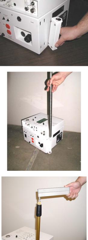
- Insert the support pole brackets into the mounting holes on the side of the base unit, make sure the bracket is mounted with the bigger hole on the top;
- Insert the support pole into the support pole bracket on the side of the base unit;
NOTE
There is a place for a support pole bracket on both sides of the base unit, allowing the unit to be set-up for either left or right hand operation
- Insert zero, one or two extension arms into the top of the support pole;
© 2004 Bell Dental Products, LLC. All rights reserved. No portion may be copied or reproduced without express written permission from Bell Dental Products, LLC.
24
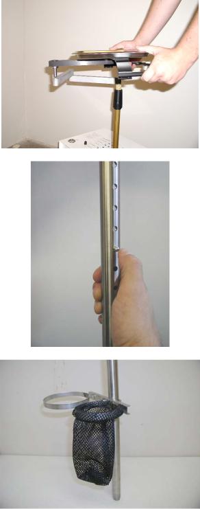
- Insert the instrument tray into the extension arm(s);
CAUTION
Do not put more than 10 pounds on the instrument tray
- Adjust the height of the instrument tray to the desired height by depressing the spring loaded button on the support pole and adjusting the height to the desired level;
-Attach the waste/water container holder bracket to the support pole. Position the bracket between 2 holes at the desired location and tighten the wing nuts;
-Fill the water bottle with clean water;
© 2004 Bell Dental Products, LLC. All rights reserved. No portion may be copied or reproduced without express written permission from Bell Dental Products, LLC.
25
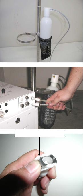
- Insert the water bottle into the water bottle holder;
- Connect the water bottle air and water fittings to the base unit by firmly pushing them into the fittings on the base unit;
Pressing the release tab
NOTE
The quick disconnect release tab on the fittings must be in the release position to insert the fitting. Press the release tab to set it in the release position.
- Position the air storage tank close to the base unit;
© 2004 Bell Dental Products, LLC. All rights reserved. No portion may be copied or reproduced without express written permission from Bell Dental Products, LLC.
26
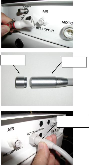
- Connect the air storage tank air hose to the base unit and air storage tank;
Air hand piece adapter
- Check the motor end of the motor hose for the air hand piece adapter. If the adapter is attached remove the adapter. Store the adapter in the hand piece pouch;
Motor end of motor hose
- Connect the motor hose to the base unit and place the motor end in the holder on the instrument tray;
CAUTION
Insert the fitting into the receptacle, slide the connector collar into the receptacle and gently rotate it until it goes into the receptacle, then gently rotate it 1/8 turn clockwise until it clicks to latch DO NOT over tighten.
- Connect the motor to the motor hose;
Motor Hose
Connector Collar
CAUTION
Care must be taken to connect the motor to the motor hose. The thread is very fine and can easily be stripped.
© 2004 Bell Dental Products, LLC. All rights reserved. No portion may be copied or reproduced without express written permission from Bell Dental Products, LLC.
27
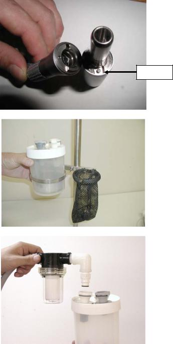
- Attach the desired hand piece to the motor, make sure the fiber optic button is aligned with the recess in the motor;
Recess
- Insert the waste container into the holder ring on the bracket;
- Connect the vacuum hose to the waste container by inserting the water trap fitting into the white fitting on the top of the waste container;
© 2004 Bell Dental Products, LLC. All rights reserved. No portion may be copied or reproduced without express written permission from Bell Dental Products, LLC.
28
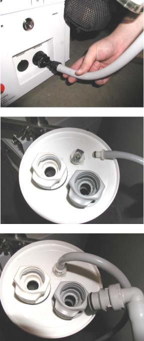
- Connect the vacuum hose to the black vacuum connector on the base unit;
- Connect the saliva ejector tube to the waster container and place it in the holder on the instrument tray;
- Connect the HVE tube to the waster container and place it in the holder on the instrument tray;
© 2004 Bell Dental Products, LLC. All rights reserved. No portion may be copied or reproduced without express written permission from Bell Dental Products, LLC.
29
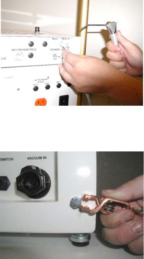
-Connect the air/water syringe to the base unit and place it in the holder on the instrument tray;
-Confirm that the power switch is in the OFF position. Connect the power cord to the connector;
-Connect the ground cable to the ground lug if necessary.
THE UNIT IS SET-UP AND READY
FOR USE
© 2004 Bell Dental Products, LLC. All rights reserved. No portion may be copied or reproduced without express written permission from Bell Dental Products, LLC.
30
Loading...