

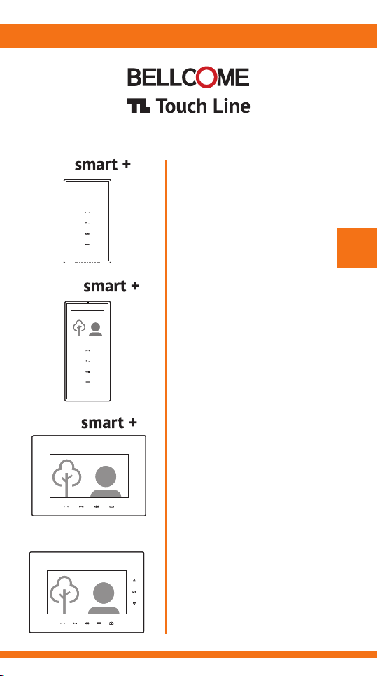
Audio
3.5" Video
7" Video
4 wires
AUDIO & VIDEO TERMINALS
for TL door phone systems
User manual
EN
7" Video
advanced
0
Safety instructions
1
Description of the audio-video terminals
2
Functions of the audio-video terminals
3
Recommended cables. Installation.
4
Use of the audio-video terminals
5
1
Any intervention on the installation must be performed by AUTHORIZED PERSONNEL!
EN
1
ContentsEN
Settings of the audio-video terminals
6
Programming the audio-video terminals
7
Use of the outdoor panels
8
Maintenance of the door phone components
9
Warranty
10
EN
Safety instructions
DO NOT power the product at 110 – 230 Va.c.!
DO NOT hit the glass screen with hard objects!
If the glass screen is broken, DO NOT touch the product.
Protect the products against lime and dust during renovation activities.
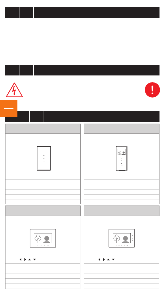
Description of the audio-video terminals
EN
2
smart+ audio terminal
ATM.0S402
ABS case
+ chemically toughened glass
170x96x22 mm
0,3 kg
o o
0 C … + 45 C
IP31
+U = 12 … 14 Vd.c.
smart+ video terminal
VTM.7S402
ABS case
+ chemically toughened glass
smart+ video terminal
+ chemically toughened glass
3.5" LCD TFT 320 (RGB) x 240
212x96x22 mm
+U = 12 … 14 Vd.c.
advanced video terminal
+ chemically toughened glass
VTM.3S402
o o
0 C … + 45 C
VTA.7S902
ABS case
0,4 kg
IP31
ABS case
7“ LCD, TFT, 800 x 3 (RGB) x 480
/ / / - 60 / 60 / 40 / 60
162x227x20 mm
0,8 kg
o o
0 C … + 45 C
IP31
+U = 12 … 14 Vd.c.
7“ LCD, TFT, 800 x 3 (RGB) x 480
/ / / - 60 / 60 / 40 / 60
162x227x20 mm
0,8 kg
o o
0 C … + 45 C
IP31
+U = 12 … 14 Vd.c.
Functions of the audio-video terminals
DBL2
DBL1
GN G2
Vin
GND
C/D
+U
Vout
GN G1
GND
EN
3
Main functions
Call, answer and hands-free talk
Video image display (color during day, black & white during night) during the call, talk,
monitoring and access
Audio-video monitoring with bidirectional talk
Access command during call, talk and monitoring
Additional command – AUX key for an auxiliary automation
Additionally, only for the advanced video terminals
Picture taking during call, talk and monitoring
Picture memory of up to 100 images. Visualize/ delete pictures
Date and time display
Settings
Call and talk volume adjustment: 7 levels and silent (mute)
Ringtone selection: 5 options
Call duration selection: 1 x 5 sec., 2 x 5 sec., 3 x 5 sec. or 1 min. continuously
Video image adjustment: brightness, chrominance
Date and time setting
Extensions
Auxiliary command: auto gate, garage door, outdoor lighting etc.
Successive video monitoring, when additional video cameras are connected
1 additional video terminal and/or 3 additional audio terminals, connected to the main terminal
Entrance doorbell, connected directly to the terminal
Acoustic (Gong type) or visual call signaling device, connected directly to the terminal
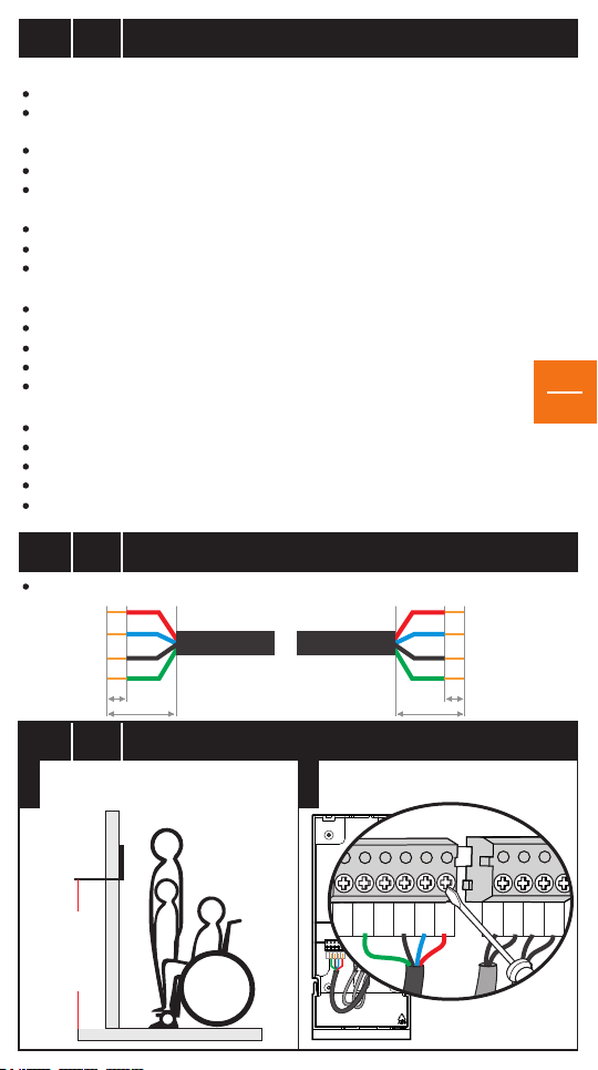
Recommended cables. Installation.
EN
4
4 wires x 0.5 mm (type H03VV-F4G 0.5) for maximum 75 lm
GND
Vout
C/D
+U
2
6mm
25-30mm
25-30mm
6mm
+U
C/D
GND
Vin
EN
2
EN
4.1
Fasten the back case on the wall H=135cm
Fasten the connectors on the back case
STEP 1
Installation of the smart+ Audio-Video Terminal
135 cm
Make the connections in the connector
fastened on the back case.
STEP 2
+U
C/D
Vin
Vout
GND
GONG2
GONG1
DBL2
DBL1
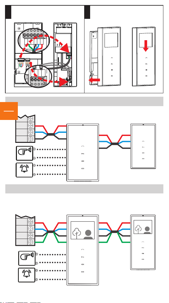
Move the connector with the fastened
Vin
GND
C/D
+U
Vout
GND
GNG1
GNG2
DBL1
DBL2
C/
D
+
U
GND
C/
D
+
U
GND
V
o
u
t
wires from the back case to the front
STEP 3
case.
+U
C/D
Vin
Vout
GND
GONG2
GONG1
DBL2
DBL1
1. Place the front case with the fastened
connectors over the back case.
STEP 4
2. Pull the terminal down until it interlocks.
2
+U
Vin
C/D
Vout
GND
GNG2
GNG1
DBL1
DBL2
1
EN
3
SCU/VCB/ACB
OUT-x
DOORBELL
GONG
SCU/VCB
OUT-x
DOORBELL
GONG
Connection diagram for the AUDIO terminal
AUDIO TERMINAL Additional
+U
C/D
GND
+U
C/D
GND
DBL1
DBL2
GNG1
GNG2
ATM.0S402
+U
C/D
GND
Connection diagram for the 3.5” VIDEO terminal
VIDEO TERMINAL
VTM.3S402
+U
C/D
GND
Vout
+U
C/D
GND
Vin
DBL1
DBL2
GNG1
GNG2
+U
C/D
GND
Vout
terminal
+U
C/D
GND
Additional
terminal
+U
C/D
GND
Vin

Installation of the VTM.7S402/ VTA.7S902 smart+/ advanced Video Terminal
C
/
D
+U
G
ND
Vo
u
t
GNG2
GNG1
DBL2
DBL1
GND
C/D
+U
+U
GND
Vin
Vout
GNG2
GNG1
DBL2
DBL1
GND
C/D
+U
+U
GND
Vin
Vout
EN
4.2
Fasten the back case on the wall H=135cm
Fasten the connectors on the back case
STEP 1
135 cm
Make the connections in the connector
fastened on the back case.
STEP 2STEP 4
+U
+U
Vin
C/D
Vout
GND
GND
DBL2
DBL1
GOG2
GOG2
Move the connector with the fastened
wires from the back case to the front
STEP 3
case.
Connection diagram for the 7” VIDEO terminal
SCU/VCB
+U
C/D
GND
Vout
C/D
GND
Vin
VIDEO TERMINAL
VTM.7S402/VTA.7S902
+U
DBL2
DBL1
DOORBELL
1. Place the front case with the fastened
connectors over the back case.
2. Pull the terminal down until
it interlocks.
1
2
Additional
terminal
+U
C/D
GND
Vin
GNG1
GONG
+U
C/D
GND
Vout
GNG2
EN
4

Use of the audio-video terminals
EN
5
Use of the smart+ terminals
5.1
smart+ 3.5” video
smart+ audio
EN
5
Call answer, audio-video monitoring
(setting mode: ringtone selection)
Access command
(setting mode: call duration)
Volume adjustment during talk, Mute
(setting mode: call sound volume)
Auxiliary command
(auto gate, garage door, outdoor lighting etc.)
smart+ 7” video
Call answer,
audio-video monitoring
(setting mode:
ringtone selection)
Standard settings of the producer:
Ringtone
1.
Call duration
2.
Call sound volume
3.
1. STAND-BY: The keyboard is not backlighted.
2. APEL DE LA PANOUL EXTERIOR: The terminal rings for maximum 1 min., with the
selected ringtone. All the keys light up, and the key blinks. The display shows the image
with the visitor.
- During the call, the conversations that take place indoors cannot be heard outdoors.
- You can hear and see what goes on at the entrance!
Volume adjustment during CALL: Successively touch the key. The maximum level (7) is
signaled with two beeps (2 x [ ]). After the maximum level is reached, the adjustment
recommences at level 1. This adjustment will not be stored. All the calls will start with the
set level for the call sound volume (see the settings section).
3. CALL FROM THE DOORBELL OF THE RESIDENCE. The terminal rings with a specified
ringtone, set by the producer. The video display remains turned off.
4. CALL ANSWER + TALK. To answer and initiate the talk, press the key, which will remain
permanently backlighted. The talk takes place hands-free, during maximum 2 min.
- The talk may be ended without granting access, by touching the key.
Access command
(setting mode:
call duration)
BEEP
Volume adjustment
during talk, Mute
(setting mode:
call sound volume)
Ding-dong (first in the list)
2 calls
Level 5 out of 7
Auxiliary command
(auto gate,
garage door,
outdoor lighting etc.)

The image closes and the keys remain backlighted for 10 more sec. Volume adjustment during
TALK: Successively press the speaker key - . The maximum level (7) is signaled with two
beeps (2 x [ ]). After the maximum level is reached, the adjustment recommences at level 1.
BEEP
5. ACCESS COMMAND. DOOR/ GATE OPENING. From the terminal, you may control the
opening of the door/gate, in the following situations:
a. During TALK. If you decide to grant access to the visitors, touch the key. The terminal
remains on for 10 more sec. You can hear and see what goes on at the entrance!
b. During audio-video MONITORING. If you decide to open the door/gate, touch the key.
The terminal remains on for 10 more sec. You can hear and see what goes on at the entrance!
c. In STAND-BY mode. If you decide to open the door/gate, long touch (2-3 sec.) the key.
The terminal remains on for 10 more sec. You can hear and see what goes on at the entrance!
6. ADDITIONAL “AUX” COMMAND. The Touch Line door phones allow the connection of an
additional automation to the AUX terminals of the central unit: auto gate, garage door, outdoor
lighting system etc. If such an automation is connected, you may control it from the terminal
through the key. The AUX command can be performed in the following situations:
a. During TALK. If you decide to give the AUX command, touch the key.
The terminal remains on for 10 more sec. You can hear and see what goes on at
EN
6
the entrance!
b. During audio-video MONITORING. If you decide to give the AUX command, press the
key. The terminal remains on for 10 more sec. You can hear and see what goes on at
the entrance!
c. In STAND-BY mode. If you decide to give the AUX command, long touch (2-3 sec.) the
key. The terminal remains on for 10 more sec. You can hear and see what goes on at
the entrance!
7. AUDIO-VIDEO MONITORING. From the STAND-BY mode, touch the key. Monitoring,
video image + bidirectional talk last maximum 15 sec.
- During monitoring, you can see and hear what goes on at the entrance, you can talk
two-ways and you may control ACCESS ( ) and AUX ( ).
- In a building with multiple apartments, simultaneous monitoring cannot be performed.
8. AUDIO SILENT MODE (MUTE). If you do not want to be disturbed by visitors, from
STAND-BY mode, long touch (2-3 sec.) the key. The LED of the key turns on and remains
permanently red. In case of a call, the image with the visitor is displayed, but the terminal
does not ring.
- To exit the silent mode, short touch the key. The LED becomes white again.
9. IMAGE ADJUSTMENT for the smart+ VIDEO terminals.
This adjustment is made only if the colors on the display do not coincide with reality.
With the terminal in MONITORING mode, adjust the image with very small rotations of the
color and brightness adjusters on the back of the terminal.

5.2
EN
Use of the advanced terminal
advanced 7” video
ok
Scroll up
Menu / ok
Scroll down
Call answer,
audio-video monitoring
(setting mode:
ringtone selection)
NOTE: The advanced video terminal fulfills all the smart+ functions
EN
(1-9), as well as the functions presented hereinafter.
7
10. PICTURE TAKING. At each call from the outdoor panel, the terminal automatically
Access command
(setting mode:
call duration)
Volume adjustment
during talk, Mute
(setting mode:
call sound volume)
Auxiliary command
(auto gate,
garage door,
outdoor lighting etc.)
Picture taking
100 stored
pictures
stores the picture of the visitor. During the talk, you can take additional pictures, by touching
the key. The terminal can store maximum 100 pictures, and when the memory is full,
the oldest pictures are deleted, on the First In – First Out principle.
11. VISUZALIZE/DELETE PICTURES. Touch the key and enter the Menu.
Successively touch the key until you reach the Pictures menu.
ok
Using the keys, choose View Pictures or Delete all. Press to select.
ok
ok
In View Pictures, scroll using the keys and visualize all the pictures.
In Delete all, if you press the key, all pictures are deleted.
ok
After 12 sec. of not using the Menu keys, the terminal automatically returns to the normal
functioning mode.
12. IMAGE ADJUSTMENT for the advanced VIDEO terminals. This adjustment is made only if
the colors on the display do not coincide with reality.
With the terminal operating, touch the key and enter the Menu.
Successively touch the key, until you enter the Display menu.
ok
Scroll using the keys and touch to select Brightness, Chroma or Contrast.
Adjust the parameters using the keys and touch to set the desired value.
ok
ok
ok
Select Exit to exit the Display menu.
EN
6
6.1
Long touch keys , simultaneously. The terminal enters settings mode and
0
issues a long warning beep. You have 2 min. available for settings 1, 2 and 3.
Settings of the audio-video terminals
1. CALL RINGTONE 2. CALL DURATION 3. CALL RINGTONE VOLUME
CALL RINGTONE The first ringtone. Touch the key. Listen to the first ringtone.
The second ringtone. Touch the key again. The second ringtone will play.
1
For the third, the fourth and the fifth ringtone, repeat the procedure above.
The last played ringtone remains stored for the call.

CALL DURATION The terminal rings only once. Touch the key again.
The terminal rings twice. Touch the key for the second time.
The terminal rings three times. Touch the key for the third time.
2
The terminal rings continuously for 1 minute. Touch the key for the fourth time.
The last played version remains stored for call.
CALL RINGTONE VOLUME Successively touch the key, until you reach the desired
volume of the ringtone. Each volume level, from 1 to 7, is signaled by an increase in the
3
intensity of the selected ringtone.
The last played version remains stored for the call.
The settings mode will automatically close after 7 sec. from the last action.
4
TIME and DATE setting for the advanced terminal
6.2
Touch the key and enter the Menu.
Continue to touch the key until you reach the Time & Date.
Scroll using the keys and touch to select the Time or the Date.
Adjust the parameters using the keys and touch the key
for the correct setting. Select Exit to exit the Time & Date menu.
The manual programming of the address of the terminal (apartment number/ family)
All Touch Line terminals are programmed from the factory with address 1.
The terminals from apartments with numbers from 2 to 9999 will be programmed with
the number (address) of the respective apartment / family.
The address of the terminals with numbers from 2 to 20 can be manually programmed,
according to the following procedure:
0. The entire door phone system is installed and set under tension.
1. Go to the place where the SCU central unit of the installation is mounted. Long press
(2-3 sec.) the PROG button. The red LED turns on.
2. Return to the terminal and long touch the key. You will hear a long beep.
- Programming address 1: touch the key once. A short beep is issued.
- Programming address 2: touch the key twice. Two short beeps are issued.
- Programming address 3: touch the key three times. Three short beeps are issued.
Repeat the procedure for the next addresses, until 20.
NOTE: After pressing the key n times, wait a few seconds for the acoustic confirmation
of the terminal for address n. The terminal will issue n beeps for address n programmed
in the terminal.
3. Return to the SCU central unit of the installation. Press the PROG button for a short time.
The red LED turns off. The installation returns to normal functioning mode.
For programming the Touch Line terminals installed in buildings with a high number
of apartments (higher than 15), purchase the special terminal address programming
device from the producer.
ok
ok
ok
ok
Programming the audio-video terminals
EN
7
EN
8

EN
8
Use of the outdoor panels
IR LED
(night lighting)
Orientable video camera
Name 5
Name 1
Touch key
with the name
of the family
Name 4
Name 4
Name 3
Name 4
Name 3
Name 2
Name 1
Electronic display
Touch keyboard
RFID reader
1 Fam. House 8 Fam. House 10-255 Fam.
1. STAND-BY. The keys with the names of the residents/ the call keyboard are
EN
permanently backlighted during night. The red LED blinks and signals the possibility
of video monitoring.
9
Apartment building
2.1. CALL + TALK from outdoor panels with maximum 10 families. Touch the key
corresponding to the name of the family you are looking for. The panel signals the action
acoustically, with a ding-dong. The call lasts maximum 1 minute. Each touch of the key
reinitiates the call. If the resident answers, the talk mode is activated. The talk takes place
hands-free, during maximum 2 min.
2.2. CALL + TALK from outdoor panels for apartment buildings.
Use the keyboard to dial the number of the desired apartment (maximum 4 digits).
The panel signals the action acoustically, with ding-dong. The key turns red and the
following message appears on the display:
The call lasts maximum 1 minute.
T
o
C
a
l l i
N ame 1
a b o r t
Pr e s s
n g
d i
:
a l
If you do not know the number of the apartment, search for the name of the resident in the
electronic list by touching the key. Successively touch the key until the name of the
family and the apartment numbers show up on the display:
1: N a
N ame 2
2
:
N ame 3
3
:
-
m
e 1
N e x t
pa g e
If the resident answers, talk mode is initiated. The key turns green and the following
message is shown on the display:
S P E A K
!
The conversation takes place hands-free, during maximum 2 min.
4. RFID card ACCESS. Approach the RFID card to the area marked with the symbol.
The panel commands the opening of the door/gate and issues a confirmation beep sequence.
At the panel for apartment buildings, the display shows the following message:
The door/gate remains open for maximum 10 sec.
S
E
ACC
GRANTE D

Maintenance of the door phone components
EN
9
The Touch Line audio-video terminals must be kept away from water, lime or any liquid
substances, blows, fumes, powders, dust etc. In case of renovation activities, the entire surface
of the terminals will be protected with plastic foil.
The Touch Line outdoor panels must be kept away from corrosive substances, lime and blows.
For cleaning the glass screens, use a clean cloth and a special solution for glass washing.
DO NOT undo the electrical connections of the video door phone installation components.
DO NOT short-circuit the electrical connections of the video door phone installation
components.
The accumulator, optionally connected to the central unit of the video door phone installation,
must be replaced in case of defects or after exceeding its lifespan.
Warranty
EN
10
a. Warranty is granted according to the current legislation in the buyer's country of residence,
based on the purchase documents.
b. Warranty is granted for the hidden defects of the components used in production and
in case of the system not functioning according to the present user manual.
WARRANTY IS NOT GRANTED FOR:
c. Inappropriate installation and use.
d. Deterioration, intentional blows.
e. Unauthorized interventions to any of the components of the installation.
f. Theft, fire, natural disasters.
g. Lack of protection of the installation components in case of renovation activities.
EN
10

Building Communications GmbH
ELECTRA
Bischoffgasse 5/3-4, 1120 Wien - AT
+43 1 810 20 99
support@bellcome.com
www.bellcome.com
ELECTRA s.r.l
Bd. Chimiei nr.8,Iași - 700291 - RO
www.electra.ro
BELLCOME is a trademark of ELECTRA Group - No. 013502646 EUIPO - Alicante, Spain
BELLCOME is a trademark of ELECTRA Group - No. 1732510 MPI - Ciudad de Mexico, Mexico
ELECTRA is a trademark of ELECTRA Group - No. 008958332 EUIPO - Alicante, Spain
BELLCOME/ELECTRA products are registered as Industrial Models at EUIPO - Alicante, Spain
The products are
CE certified.
Certificate by
ICPE
R
709
Designed and produced by ELECTRA Made in EU
The products are
NOM certified.
Certified
by NYCE
The products contain UL-compliant
printed circuit boards.
R
Certificate no. E307311
The products are manufactured under
Quality and Environment Management System
ISO 9001:20 08
ISO 14001:2009
Certificates no. 73 100 4856, 73 104 4856
11.2017 USM.XTM(A)02.BLY04
by TÜV HESSEN
 Loading...