

4 Wires
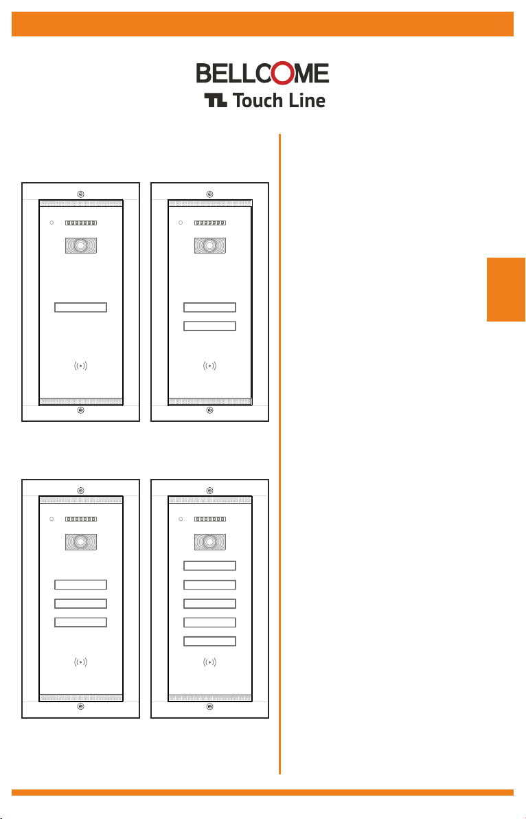
VIDEO OUTDOOR PANELS
(1 – 5 Families)
for TL door phone systems
User manual
EN
1 Fam. Video
3 Fam. Video
2 Fam. Video
5 Fam. Video
0
Safety instructions
1
Description of the video outdoor panels
2
Recommended cables. Installation.
3
Installation of the Video Outdoor Panel
4
1
ContentsEN
EN
Safety instructions
Use of the video outdoor panels
5
Maintenance of the video outdoor panels
6
Warranty
7
EN
1
Any intervention on the installation must be performed by AUTHORIZED PERSONNEL!
Protect the products against lime and dust during renovation activities.
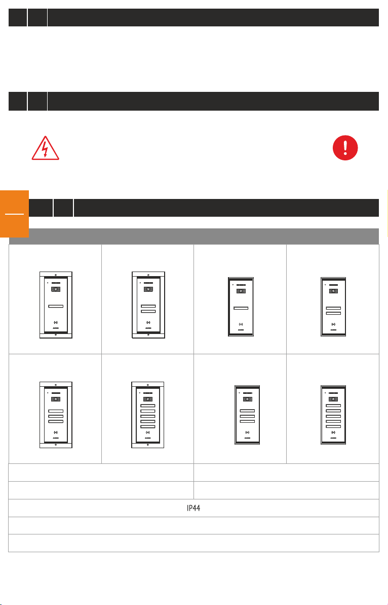
Description of the video outdoor panels
EN
2
DO NOT power the product at 110 – 230 Va.c.!
DO NOT hit the glass screen with hard objects!
If the glass screen is broken, DO NOT touch the product.
FLUSH mounting SURFACE mounting
VPA.1FR02
VPA.2FR02
VPA.5FR02VPA.3FR02
VPA.1SR02 VPA.2SR02
VPA.5SR02VPA.3SR02
294 x 144 x 53 mm
1,52 kg
= 12 … 14 Vd.c.
+U
Acces – card RFID
260 x 110 x 33 mm
1,3 kg
Case: aluminum + 4 mm chemically toughened glass
70º ± 25º orientable video camera
CMOS, 1/3", 573(H) x 597(V), 800 TVL video 1 Vpp / 75 W; PAL
IR LEDs, 850 nm, IR-CUT for night vision - 10m
TOUCH keys for call and family name, backlighted during night
Wall mounting height: 160 cm-170 cm
Weatherproof, waterproof and with an operating temperature range between -30ºC …+ 60ºC.
Electronic anti-condensation system for the video camera screen.
Anti-theft sensor that is activated during unauthorized unmounting from the wall.
Blinking red LED, signaling the presence of potential video monitoring from the panel.
In-built RFID reader. Access by secured RFID tag/card.
Allows the connection of a DVR, for extended monitoring and video recording from the panel.
3
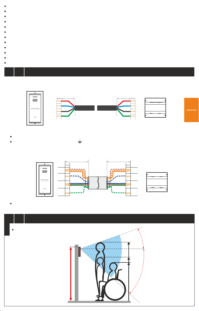
Option 1) 4 wires x 0.5 mm (type H03VV-F4G 0.5) for maximum 75 m or another type of equivalent cable
4 wires x 0.75 mm (type H05VV-F4G 0.75) for maximum 100 m or another type of equivalent cable
2
2
Recommended cables. Installation.
EN
20-25mm
6mm
+U
C/D
GND
Vin
C/D
GND
Vout
+U
6mm
20-25mm
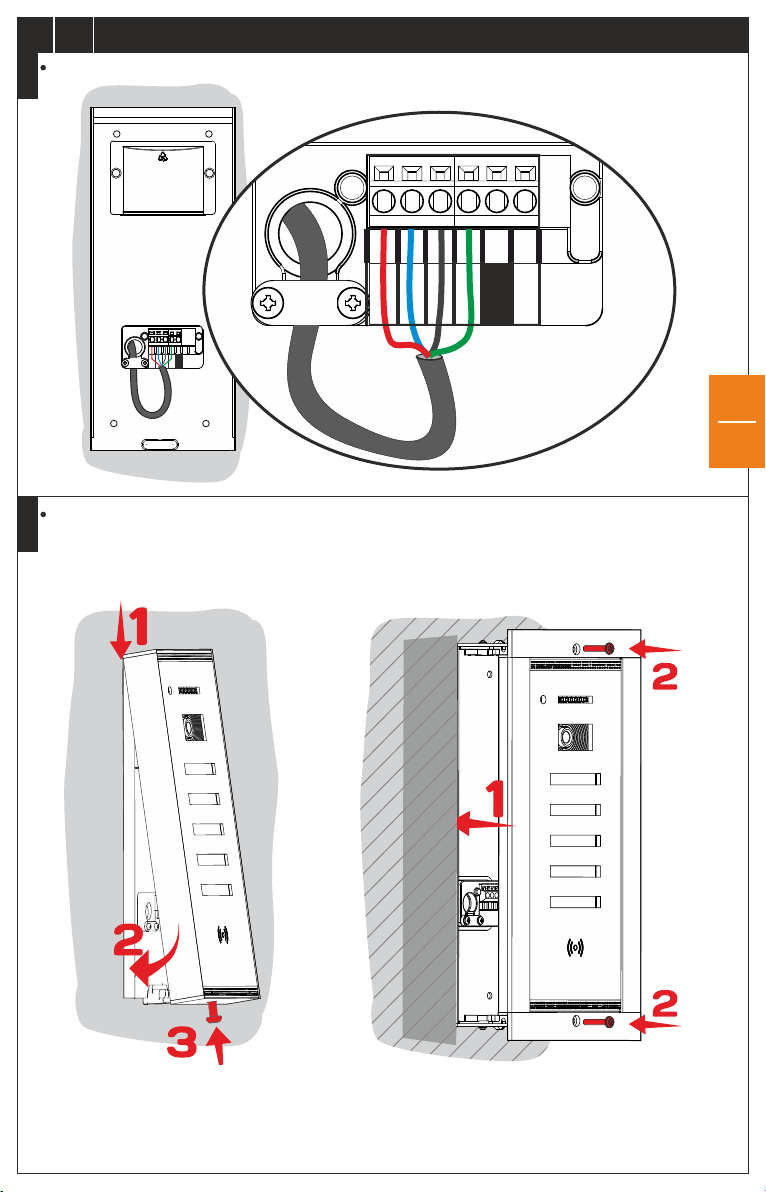
*Important:
+U C/D GND Vin/VoutMaintain the same colors for the same connections. Example: = Red, = Blue, = Black, = Green.
For electrical security reasons, connect the terminal to an earth grounding.
Option 2) UTP cat5e (AWG24) or UTP cat6e (AWG23) or TCYY - 4x2x0.5-24 AWG (max. 100m)
for maximum 250 m. The wires will be arranged as per the below table:
20-25mm
6mm
+U
C/D
GND
Vin
+U
C/D
GND
Vout
6mm
20-25mm
EN
2
Generally, any type of 4-wire cable with a 0.5 mm section is accepted. Telephone cables type TCYY - 2x2x0.5-24 AWG
(max. 30m); TCYY - 3x2x0.5-24 AWG (max. 50m); can also be used.
4
STEP 1
Installation of the advanced Video Outdoor Panel (VPA)EN
Wall installation height
70
160 cm-170cm
o
175 cm
o
130 cm
115 cm
20
o
50
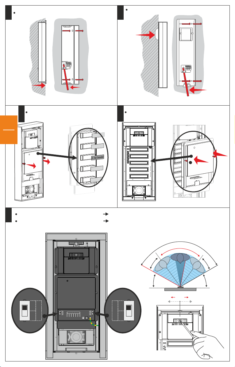
Mounting on the wall - Flush
STEP 2
Mounting on the wall - Surface
STEP 2
1.5
cm
5cm
Unmount the module and add name labels
STEP 3.1
≈20cm
Mount back the family name module
STEP 3.2
EN
3
JP 1 - Signaling of video monitoring: RED LED ON.
STEP 4
JP 2 - Setting of image recording on: DVR: DVR ON.
Video camera angle adjustment. (The video camera will be oriented towards the entrance door/gate!)
120
70
o
25
≈20cm
o
o
o
25
OFFON
o
30
o
o
70
+25
+25
OFFON
DVR
DVR
GNV
RED LED
OFF ON
+U
C/D
GND
Vout
RED LED
OFF ON
o
30
o
Electrical connections diagram for the advanced Video Outdoor Panel (VPA)
Vout
+U
C/D
GND
GNV
EN
4.1
Electrical connections in the panel
STEP 1STEP 1.1
+U
C/D
GNV
Vout
GND
Mounting the outdoor panel on the wall
GNV will not be connected!
EN
4
Surface
Flush
Torx
Torx
Torx
Important: For both types of mounting, the Torx screws for fastening the outdoor panels on the
wall will be very well tightened, to prevent the anti-theft alarm sensor from setting off.
EN
4.2
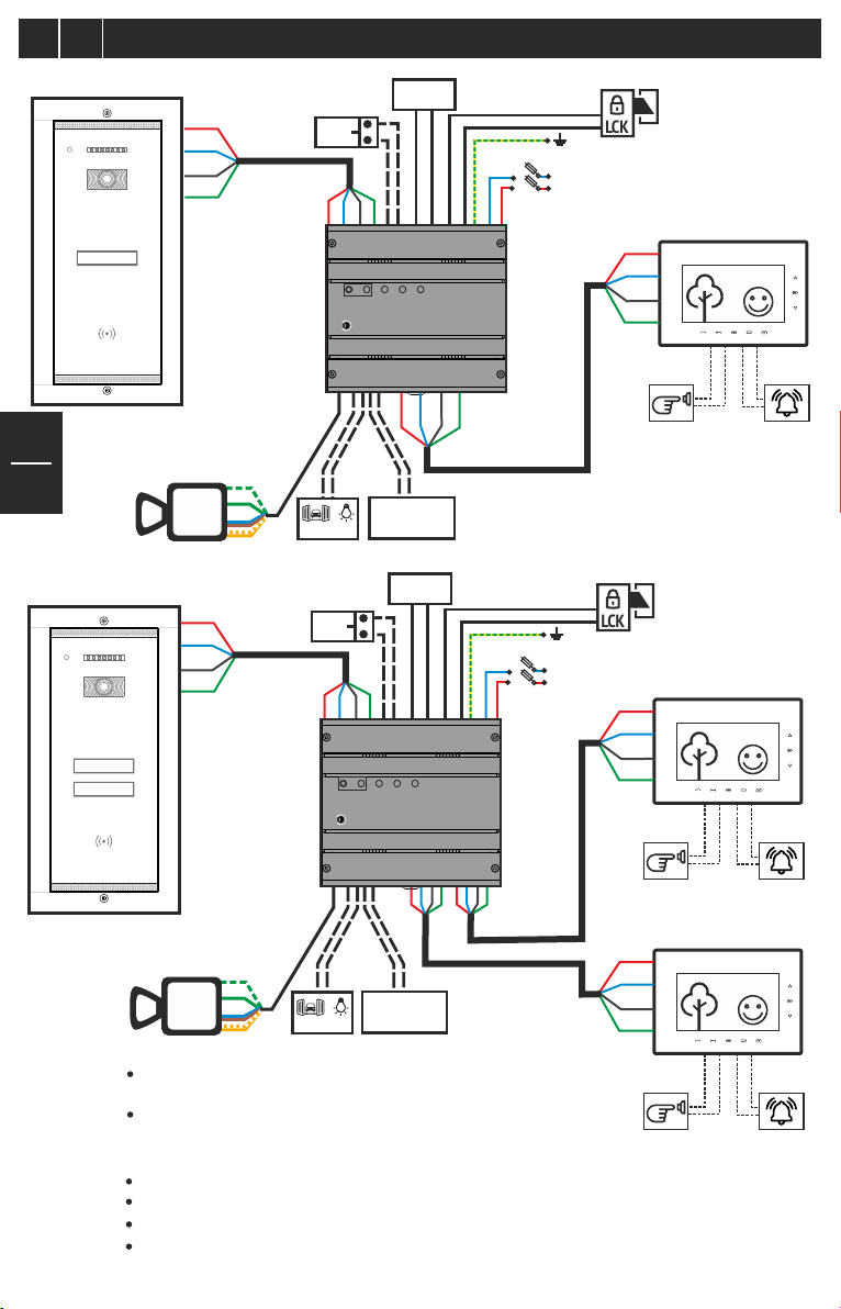
VPA (address 1)
Electrical connections diagram for 1 and 2-family residences
LOCK
SUPPLY
+U
EXIT
C/D
GND
Vout
Fam 1
Vin
C/D
GND
+U
PROG
+U
BAT 110/230V
SCU
OUT1
+U
C/D
Vout
GND
EN
Vcam
+U
C/D
GND
Vout
Vout2
GNV
GND
+U
AUX
EXIT
,
C/D
+U
max. 42Ah/12V
Vin
GND
PROG
+U
-
+
BAT
LOCK
SUPPLY
BAT 110/230V
5
VPA (address 1)
Fam 2
Fam 1
SCU
OUT1
OUT2
+U
+U
C/D
Vout
GND
Vout2
GNV
Vcam
GND
+U
AUX
,
Note: For residences with 1 family and one entrance (entrance 1),
the outdoor panel has address 1, which is set by the producer.
For multiple entrances: Entrance 2, Entrance 3, Entrance 4, panels
2, 3 and 4 will be programmed according to the procedure in Ch. 4.6.
-
+
BAT
max. 42Ah/12V
max. 24Va.c./24Vd.c.
S1: 2x6Aa.c.
N
L
max. 24Va.c./24Vd.c.
S1: 2x6Aa.c.
N
L
C/D
Vout
GND
LCK
110Va.c./50Hz
230Va.c./50Hz
C/D
GND
Vin
LCK
110Va.c./50Hz
230Va.c./50Hz
+U
C/D
GND
Vin
+U
C/D
GND
Vin
Fam. 1
(address 1)
+U
DBL2
DBL1
GONG2
Doorbell
Fam. 2 (address 2)
DBL2
DBL1
GONG2
Doorbell
Fam. 1 (address 1)
DBL2
DBL1
GONG2
Doorbell
GONG1
GONG
GONG1
GONG
GONG1
GONG
Note: Any type of TL terminal can be mounted indoors.
For Fam. 1, the terminal has address 1, which is set by the producer.
The additional terminals mounted in parallel will have the address of the main terminal
For Fam. 2, the terminal will be programmed with address 2. See Ch. 6
of the user manual for TL audio-video terminals.
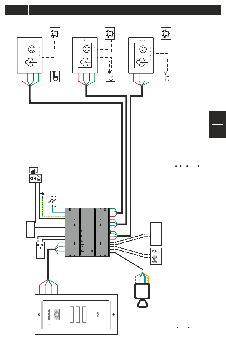
4.3
Electrical connections diagram for 3-family residences
EN
Fam. 3
(address 3)
+U
C/D
LOCK
GND
max. 24Va.c./24Vd.c.
SUPPLY
Vin
LCK
EXIT
GONG
GONG 1
GONG 2
DBL 2
DBL 1
Doorbell
110Va.c./50Hz
230Va.c./50Hz
L
N
S1: 2x6Aa.c.
Fam. 2
(address 2)
Vin
GND
C/D
+U
GONG
GONG 1
GONG 2
DBL 2
DBL 1
Fam. 1
(address 1)
+U
C/D
GND
Vin
Doorbell
+U
C/D
GND
Vin
GONG
GONG 1
GONG 2
DBL 2
DBL 1
Doorbell
EN
6
Note: Any type of TL terminal can be mounted indoors.
For Fam. 1, the terminal has address 1, which is set by the producer.
The additional terminals mounted in parallel will have the address of the
main terminal
For Fam. 2 and Fam. 3, the terminal will be programmed with address 2,
respectively address 3. See Ch. 6 of the user manual for TL audio-video
terminals.
Vout
GND
C/D
+U
Vout
GND
C/D
OUT2 OUT3
+U
PROG
BAT 110/230V
+U
SCU
OUT1
Vout
GND
C/D
+U
-
BAT
+
max. 42Ah/12V
,
AUX
VPA (address 1)
+U
C/D
GND
Vout
Fam 3
Fam 2
Fam 1
Vout2
GNV
GND
Vcam
+U
Note: For residences with 3 families and one entrance (entrance 1),
the outdoor panel has address 1, which is set by the producer.
For multiple entrances: Entrance 2, Entrance 3, Entrance 4, panels 2, 3
and 4 will be programmed according to the procedure in Ch. 4.6.

4.4
Electrical connections diagram for 5-family residences
EN
EN
7
Fam. 4 (address 4)
GND
Vin
OUT 2
GONG
GONG 1
GONG 2
DBL 2
DBL 1
Doorbell
Fam. 1 (address 1)
+U
Vin
C/D
GND
+U
C/D
GND
Vout
OUT 1
GONG
GONG 1
GONG 2
DBL 2
DBL 1
Doorbell
Fam. 2 (address 2)
+U
C/D
GND
Vin
GONG
GONG 1
GONG 2
DBL 2
DBL 1
Doorbell
GONG
GONG 1
GONG 2
DBL 2
DBL 1
Fam. 3 (address 3)
Vin
Fam. 5 (address 5)
Doorbell
+U
C/D
GND
Vin
+U
C/D
GND
GONG
GONG 1
GONG 2
DBL 2
DBL 1
Doorbell
+U
C/D
OUT
OUT 4
OUT 3
VCB
IN
LCK
110Va.c./50Hz
230Va.c./50Hz
L
N
+U
C/D
GND
Vin
Note: Any type of TL terminal can be mounted indoors..
For Fam. 1, the terminal has address 1, which is set
by the producer.
The additional terminals mounted in parallel will have the
address of the main terminal
For Fam. 2, 3, 4 and 5, the terminal will be programmed with
address 2, respectively addresses 3, 4 and 5. See Ch. 6
of the user manual for TL audio-video terminals.
LOCK
VPA (address 1)
max. 24Va.c./24Vd.c.
S1: 2x6Aa.c.
Vout
GND
SUPPLY
Vin
GND
C/D
C/D
GND
+U
Vout
Fam 5
EXIT
+U
Fam 4
Fam 3
BAT 110/230V
+U
PROG
Fam 2
SCU
Fam 1
OUT1
C/D
+U
Vout2
GNV
+
,
GND
Vcam
BAT
AUX
+U
max. 42Ah/12V
Note: For residences with 5 families and one entrance (entrance 1),
the outdoor panel has address 1, which is set by the producer.
For multiple entrances: Entrance 2, Entrance 3, Entrance 4,
panels 2, 3 and 4 will be programmed according to the
procedure in Ch. 4.6.
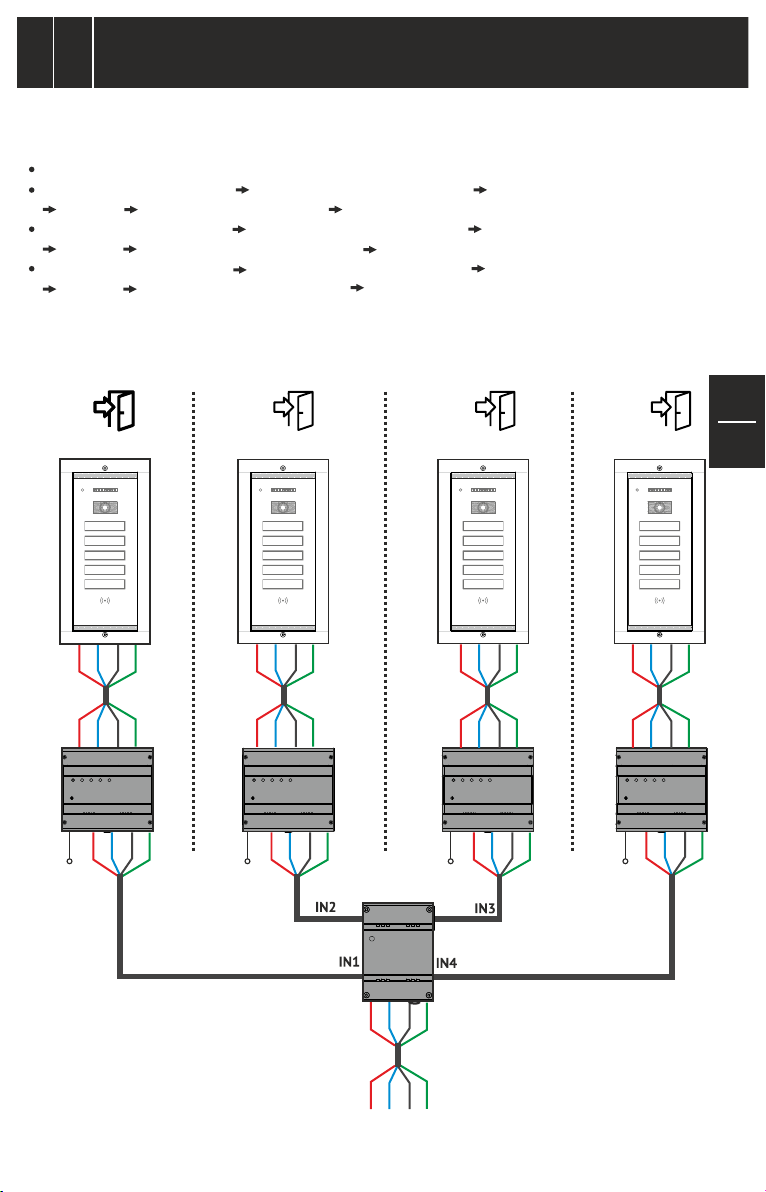
Electrical connections diagram for multiple parallel panels
EN
4.5
Important: One VPA outdoor panel and one SCU central unit will be mounted at each entrance.
The programming of the addresses for the panels connected in parallel is done as follows:
The VPA1 panel keeps address 1, which is set from the factory.
The VPA2 panel with address 2 Long press the PROG. button at SCU 2 Long touch the Fam.1 key at the VPA2 panel.
long beep Short touch the Fam.1 key, twice Two short beeps confirmation.
The VPA3 panel with address 3 Long press the PROG. button at SCU 3 Long touch the Fam.1 key at the VPA3 panel.
long beep Short touch the Fam.1 key, three times Three short beeps confirmation.
The VPA4 panel with address 4 Long press the PROG. button at SCU 4 Long touch the Fam.1 key at the VPA4 panel.
long beep Short touch the Fam.1 key, four times Four short beeps confirmation.
Note: After the beep confirmation of the new address in the panel, go to the SCU of the panel and short press the
PROG. button. The programming of the address is finished.
(more entrances in a building)
1 2 3 4
VPA1 (address 1)
Fam 5
Fam 4
Fam 3
Fam 2
Fam 1
+U
C/D
GND
Vout
+U
Vin
C/D
GND
SCU1 SCU2 SCU3 SCU4
OUT 1
+U
C/D
GND
110Va.c.
230Va.c.
Vout
VPA2 (address 2)
Fam 5
Fam 4
Fam 3
Fam 2
Fam 1
+U
C/D
GND
Vout
+U
Vin
C/D
GND
OUT 1 OUT 1 OUT 1
+U
C/D
GND
110Va.c.
230Va.c.
Vout
VPA3 (address 3)
110Va.c.
230Va.c.
VSB
Fam 5
Fam 4
Fam 3
Fam 2
Fam 1
+U
C/D
GND
Vout
+U
Vin
C/D
GND
+U
C/D
GND
Vout
VPA4 (address 4)
Fam 5
Fam 4
Fam 3
Fam 2
Fam 1
+U
C/D
GND
Vout
+U
Vin
C/D
GND
+U
C/D
GND
110Va.c.
230Va.c.
EN
8
Vout
+U
C/D
GND
Vout
+U
Vin
C/D
GND
To one or
more families

Use of the Video Outdoor Panels
EN
5
145 mm
115 mm
274 mm
Fam 1
294 mm
EN
1. STAND-BY: The call keys with the name of the residents are permanently backlighted during night. The Red LED
blinks permanently.
9
Note: The Red LED can be disabled through jumper JP1 (RED LED) on the board of the keyboard, when the
name labels are added.
2. CALL: Touch the key corresponding to the name of the family you are looking for. The call is acoustically signaled
with a ding-dong. Each touch of the key reinitiates the call.
3. TALK: If the resident answers, talk is initiated. The maximum duration of the talk is 2 min.
4. END OF TALK: - After 1 min. from the call, if the resident does not answer.
- At 10 sec. after the door/gate is opened.
- Immediately, if the resident decides to end the talk without opening the door/gate.
5. ACCESS: The door/gate will be open during the time set at the SCU (maximum 10 sec.). Access granting is
acoustically signaled through a confirmation beep sequence.
6. RFID CARD ACCESS: If you program the RFID cards in the outdoor panel, each resident of the building has
access using the secured RFID card from BELLCOME. Approach the card to the RFID area marked on the
outdoor panel. The access is signaled acoustically, through a confirmation beep sequence, and visually – the
symbol blinks white.
EN
5.1
At the moment of the delivery from the factory, the TL video outdoor panels do not have access cards memorized.
In order to have access in the building after installation, it is mandatory to program the RFID cards in the
outdoor panel.
During programming the installation has to be connected to the grid (110V/230Va.c.) and fully operational.
1. Go to the place where the SCU central unit of the installation is mounted. Long press (3 sec.) the PROG button on
the SCU. The Red LED turns on.
2. Take the RFID cards to the outdoor panels. To program them, approach every card for one second to the
RFID area of the outdoor panel. For each programmed card, the panel issues two short beeps. Repeat this step
for programming all the RFID cards.
3. Go to the place where the SCU central unit of the installation is mounted. Short press the PROG button on the SCU.
The Red LED turns off. The installation returns to normal functioning, successfully ending the programming mode.
EN
5.2
This procedure applies when you wish to give up access with RFID cards. During the deletion of the RFID cards,
the installation has to be connected to the grid (110V/230Va.c.) and fully operational.
1. Go to the place where the SCU central unit of the installation is mounted. Long press (3 sec.) the PROG button on
the SCU. The Red LED turns on. The installation enters programming mode:
1 Fam. 5 Fam.
Manual programming of the RFID Cards in the panel/
Adding a new RFID Card in the panel.
Deleting the RFID Cards from the panel
2 Fam., 3 Fam.
Fam 5
Fam 4
Fam 3
Fam 2
Fam 1
Fastening Torx screw
Microphone
IR LEDs
(night lighting)
Orientable video camera
Touch keys for call,
with the name of the residents
RFID reader.
RFID tag/card access
Speaker
Fastening Torx screw

2. To delete the RFID access cards from the memory of the panel:
- Long touch the Fam. 1 key until the acoustic confirmation of the panel with a long beep.
- Short touch the Fam. 1 key 7 times. The panel issues two short confirmation beeps.
- Immediately after, long touch (2-3 sec.) the Fam. 1 key. All the codes of the RFID access cards are deleted
permanently. The action is acoustically confirmed by a long beep.
3. Go to the place where the SCU central unit of the installation is mounted. Short press the PROG button on the SCU.
The Red LED turns off. The installation returns to normal functioning mode.
4. Optional: From the outdoor panel, check if the old RFID cards grant access. When each RFID card that has
been deleted from the memory is approached to the panel, a low frequency beep will be issued.
6
The Touch Line outdoor panels must be kept away from corrosive substances, lime and blows. In case of renovation activities,
the entire surface of the panels will be protected with plastic foil.
For cleaning the glass surfaces, use a clean cloth and a special solution for glass washing.
DO NOT undo the electrical connections of the video door phone installation components.
DO NOT short-circuit the electrical connections of the video door phone installation components.
7
a. Warranty is granted according to the current legislation in the buyer's country of residence, based on the purchase
documents.
b. Warranty is granted for the hidden defects of the components used in production and in case of the system not functioning
according to the present user manual.
WARRANTY IS NOT GRANTED FOR:
c. Inappropriate installation and use.
d. Deterioration, intentional blows.
e. Unauthorized interventions to any of the components of the installation
f. Theft, fire, natural disasters
g. Lack of protection of the installation components in case of renovation activities.
Maintenance of the video outdoor panels
EN
Warranty
EN
EN
10

ELECTRA
Building Communications GmbH
Bischoffgasse 5/3-4, 1120 Wien - AT
+43 1 810 20 99
ELECTRA s.r.l
Bd. Chimiei nr.8,Iași - 700291 - RO
www.electra.ro
support@bellcome.com
www.bellcome.com
BELLCOME is a trademark of ELECTRA Group - No. 013502646 EUIPO - Alicante, Spain
BELLCOME is a trademark of ELECTRA Group - No. 1732510 MPI - Ciudad de Mexico, Mexico
ELECTRA is a trademark of ELECTRA Group - No. 008958332 EUIPO - Alicante, Spain
BELLCOME/ELECTRA products are registered as Industrial Models at EUIPO - Alicante, Spain
The products are
CE certified.
Certificate by
R
709
ICPE
The products contain UL-compliant
Designed and produced by ELECTRA Made in EU
printed circuit boards.
Certificate no. E307311
R
The products are manufactured under
Quality and Environment Management System
ISO 9001:2015
ISO 14001:2015
Certificates no. 73 100 4856, 73 104 4856
by TÜV HESSEN
06.2019 USM.VPA.5XR02.BLY04
 Loading...