

Bellcome VPA.1FR02 User Manual
VIDEO OUTDOOR PANELS
(1 – 5 Families)
for TL door phone systems
User manual
4 wires
1 Fam. Video
2 Fam. Video
3 Fam. Video
5 Fam. Video
EN
0
ContentsEN
1
Safety instructions
2
Description of the video outdoor panels
4
Recommended cables. Installation
5
Use of the video outdoor panels
1
Safety instructions
2
Description of the video outdoor panels
3
Functions of the video outdoor panels
= 12 … 14 Vd.c.
+U
294 x 144 x 53 mm
1,52 kg
o o
- 30 C … + 60 C
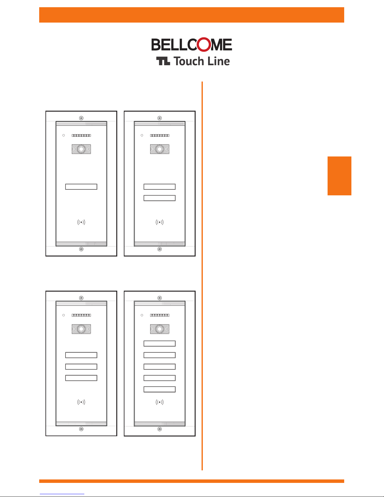
VPA.1FR02
Video outdoor panel
VPA.2SR02
260 x 110 x 33 mm
1,3 kg
= 12 … 14 Vd.c.
+U
294 x 144 x 53 mm
o o
- 30 C … + 60 C
VPA.3FR02
Video outdoor panel
VPA.5SR02
260 x 110 x 33 mm
1,3 kg
CMOS, 1/3", 573(H) x 597(V), 800 TVL
video 1 Vpp / 75 W; PAL
70º ± 25º orientable video camera
Case: aluminum + 4 mm chemically toughened glass
IR LEDs, 850 nm, IR-CUT for night vision - 10m
TOUCH keys for call and family name,
backlighted during night
Access – RFID card Access – RFID card
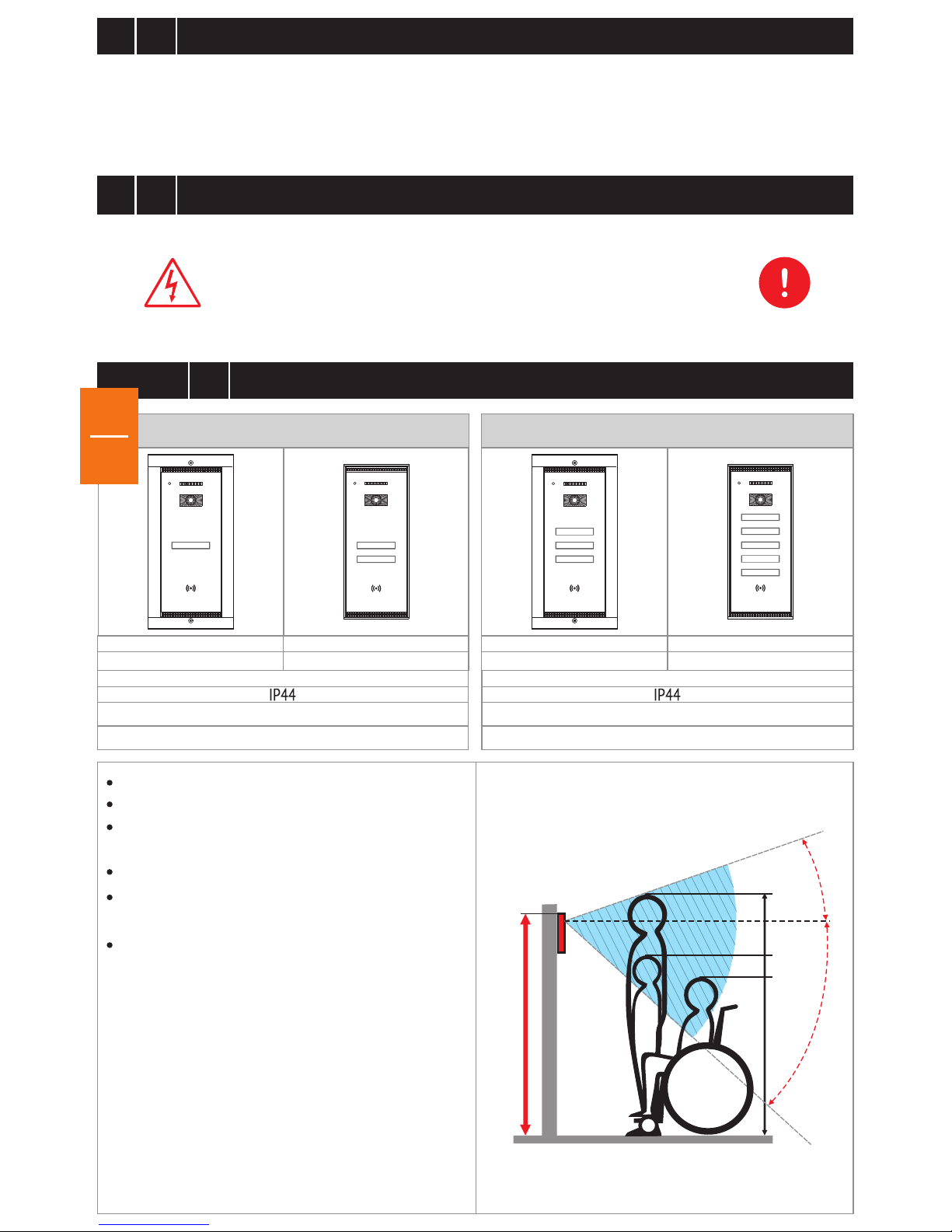
Wall mounting height: 160 cm
1,52 kg
EN
EN
Any intervention on the installation must be performed by AUTHORIZED PERSONNEL!
DO NOT power the product at 110 – 230 Va.c.!
DO NOT hit the glass screen with hard objects!
If the glass screen is broken, DO NOT touch the product.
Protect the products against lime and dust during renovation activities.
o
70
175 cm
130 cm
115 cm
160 cm
o
20
o
50
6
Maintenance of the video outdoor panels
7
Warranty
EN
1
3
Functions of the video outdoor panels
4
Recommended cables. Installation.
The outdoor panel is mounted on the wall at a height of 1.60 m from the upper edge of the panel (see page 1).
Depending on the maximum distance between the outdoor panel and the last terminal in the installation, the recommended
cables are the following:
2
Option 1) 4 wires x 0.5 mm (type H03VV-F4G 0.5) for maximum 75 lm
2
Option 2) 4 wires x 0.75 mm (type H05VV-F4G 0.75) for maximum 150 lm
Build features:
Solid mechanical construction, built in embedded technology, with chemically toughened glass.
Weatherproof, waterproof and with an operating temperature range between -30º…+ 60º C.
Electronic anti-condensation system for the video camera screen.
Anti-theft sensor that is activated during unauthorized unmounting from the wall.
Day/night sensor for the command of TOUCH keyboard backlighting and the lighting of the IR LEDs and IR-CUT.
TOUCH keyboard with the name of the resident, backlighted during night.
1/3 CMOS, 900TVL color video camera and IR LEDs for b/w image during night.
Blinking red LED, signaling the presence of potential video monitoring from the panel.
In-built RFID reader. Access by secured RFID tag/card.
Allows the connection of a DVR, for extended monitoring and video recording from the panel.
Settings/Programming
Programming and deletion of RFID building access tags/cards.
Programming of new address 2, 3 or 4, for parallel connected panels, in case of buildings with multiple entrances.
(maximum 4 outdoor panels for one building).
Enabling or disabling of video monitoring signaling (Red LED ON/OFF), through the JP1: RED LED/0. (ch. 4.1-step 4)
Enabling or disabling DVR video recording (ON/OFF) through the jumper JP40: 1-2 (OFF) / 2-3(ON) (ch. 4.1)
Extensions
Allows the parallel connection of maximum 4 outdoor panels, through a video selection box (VSB).
Allows the connection of an additional video camera directly to the central supply unit (SCU), or of 4 additional
video cameras, through a video selection box (VSB).
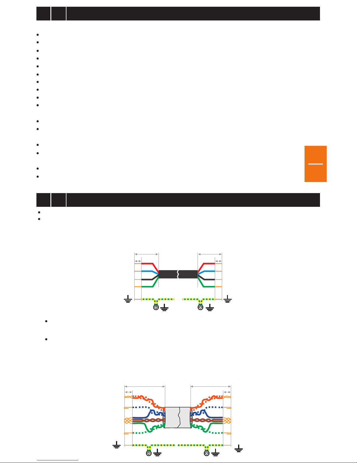
Connections
to the VPA
outdoor panel
+U
C/D
GND
+U
C/D
GND
UTP cat5e (AWG24)
UTP cat6e (AWG23)
25-30mm
6mm
VinVout
6mm
25-30mm
Connections
to the SCU
central supply unit
+U
C/D
GND
Vin
+U
C/D
6mm
25-30mm
GND
Vout
6mm
25-30mm
Connections
to the SCU
central supply unit
Connections
to the VPA
outdoor panel
EN
2
*Important:
Maintain the same colors for the same connections.
Example: +U = Red, C/D = Blue, GND = Black, Vin/Vout = Green.
For electrical safety reasons, we recommend installing an earthing cable between the panel and the SCU, connected to an
earth grounding (ISO - IEC 60950-1:2005)
Option 3) UTP cat5e (AWG24) or UTP cat6e (AWG23), for maximum 250 lm
The wires will be arranged as per the below table:
EN
EN
o
70
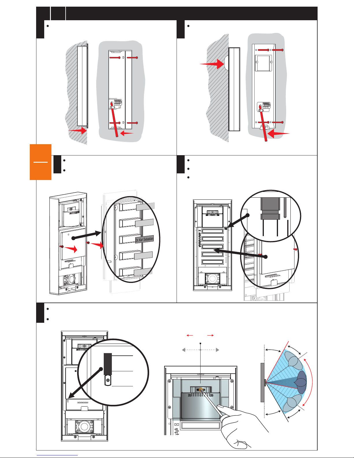
4.1
Installation of the advanced Video Outdoor Panel (VPA)
STEP 1
Mounting on the wall - Flush
Only for maximum 8 fam. video outdoor panels
Setting of image recording on DVR from the outdoor panel, with JP2: DVR
o
+25
o
+25
o
25
o
25
o
30
o
30
EN
3
5cm
≈20cm
≈20cm
1.5
cm
Mount back the family name module
Signaling of video monitoring: JP1 on RED LED position
No video monitoring signaling: JP1 on 0 position
Mounting on the wall - Surface
Unmount the module and add name labels
EN
STEP 2
STEP 3
STEP 4
STEP 5
JP1
RED
LED
0
o
70
0
JP2
DVR
DVR
JP 2
0
Video camera angle adjustment. (The video camera will be oriented towards the entrance door/gate!).
 Loading...