


4 Drähte/4 Wires/4 Hilos/4 Fils/4 Fili/4 Przewody
1/2/3 Familien
Video Türsprechanlagen KIT 3,5”/7” DE
Benutzerhandbuch
1/2/3 Families |
EN |
VIDEO DOOR PHONE KIT 3.5”/7” |
|
User manual |
|
1/2/3 Familias |
ES |
KIT VÍDEO PORTERO 3.5"/7" |
|
Manual del usuario |
|
1/2/3 Familles |
FR |
KIT VIDÉO INTERPHONE 3.5”/7” |
|
Manuel de l'utilisateur |
|
1/2/3 Famiglie |
IT |
KIT VIDEO CITOFONO 3.5"/7" |
|
Manuale dell’utente |
|
1/2/3 Rodziny
ZESTAW VIDEO INTERFON 3.5"/7" PL
Podręcznik użytkownika
INSTALLATIONSANLEITUNG - VIDEO TÜRSPRECHANLAGEN KIT
Vielen Dank, dass Sie sich für die BELLCOME Produkte entschieden haben.Wir begleiten Sie während der gesamten Garantiezeit. Für technische Unterstützung und weitere Fragen können Sie uns unter: ELECTRA Building Communications GmbH 
 +43 1 810 20 99, support@bellcome.com kontaktieren.
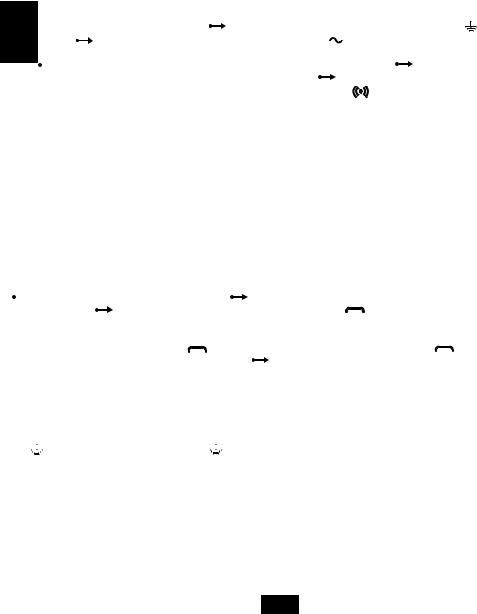
KIT-INSTALLATION. Befolgen Sie die nachstehenden Schritte in der beschriebenen Reihenfolge.
 SCHRITT 1. Lesen Sie die Diagramme in dieser Broschüre und die technischen Handbücher des KIT (VPA, VTx, SCU).
 SCHRITT 2. Stellen Sie die elektrischen Verbindungen zu den Inneneinheiten (ATM, VTM, VTA) und dann zur VPA -Außeneinheit her.
 SCHRITT 3. Die elektrischen Anschlüsse der LCK-Türschloss und LOCK SUPPLY Türschlossversorgung an der SCU- Stromversorgungseinheit und ggf. an den Anschlüssen an die EXIT-Taste anschließen; AUX zusätzliche
|
Installationen; BAT; Vcam analoge Videokamera. |
|
|
|
|
|
|
||
|
SCHRITT 4. AUTORISIERTES PERSONAL !!! LESEN SIE DIE SICHERHEITSHINWEISE AUS DEM HANDBUCH DER |
||||||||
DE |
SCU-STROMVERSORGUNGSEINHEIT !!! |
TRENNEN Sie die Sicherungen und schließen Sie die L, N, |
|
|
an die |
||||
|
|
||||||||
|
|
||||||||
SCU an |
VERBINDEN Sie die Sicherungen mit dem Stromnetz. Die |
, S2-LEDs leuchten auf und S1 |
|
|
schaltet sich nur |
||||
|
ein, wenn die Batterie (12V / max. 42Ah) angeschlossen ist. |
|
|
|
|
|
|
||
|
SCHRITT 5.1. PROGRAMMIERUNG DER HAUPTAUßENEINHEIT: RFID-KARTEN / TAGs |
Drücken Sie an der |
|||||||
SCU lange (3 Sek.) Die Taste PROG (Punkt 6). Die rote PROG-LED leuchtet |
Gehen Sie vom Haupteingang zum |
||||||||
VPA-Bedienfeld und berühren Sie jede RFID-KARTE eine Sekunde lang im Bereich |
(RFID). Für jede programmierte |
||||||||
RFID CARD / TAG gibt die Außeneinheit zwei Pieptöne aus. Befolgen Sie die gleichen Schritte, um alle RFID-Karten / TAGs für alle Bewohner des Gebäudes zu programmieren. 
 Kehren Sie zur SCU zurück und drücken Sie kurz die PROG-Taste. Die rote LED erlischt. Das Hauptbedienfeld enthält die Adresse 1, die werkseitig eingestellt und betriebsbereit ist.
 SCHRITT 5.2. PROGRAMMIERUNG DER ZUSÄTZLICHEN AUßENEINHEIT: NEUE ADREßE und RFID-KARTEN / TAGs. Wenn der Zugang im Gebäude über zwei Eingänge erfolgt, muss das zusätzliche Feld VPA2 (Punkt 11) von Eingang 2 mit Adresse 2 eingerichtet werden.
 Drücken Sie bei SCU 2 lange die Taste PROG. Die rote PROG-LED leuchtet auf.
 Berühren Sie im VPA2 -Bedienfeld die Fam.1-Taste (langer Piepton) und berühren Sie zweimal kurz die Fam.1-Taste. Die Außeneinheit bestätigt die Speicherung der Adresse 2 mit zwei kurzen Signaltönen. Fahren Sie mit der Programmierung der CARDS / TAGs im VPA2-Bedienfeld fort.
 Jede Berührung der CARD / TAG im Bereich

 wird vom VPA2 mit zwei Signaltönen bestätigt.

 Kehren Sie zur SCU2 zurück und drücken Sie kurz die PROG-Taste. Die rote LED erlischt. Die VPA2- und VPA1-Außeneinheit sind funktionsbereit, mit allen Inneneinheiten im Gebäude.
 SCHRITT 6.1 PROGRAMMIERUNG DER ADRESSE DES FAM.1-INNENEINHEIT. Die Inneneinheit behalten die Adresse 1, die vom Hersteller eingestellt ist.
 SCHRITT 6.2 PROGRAMMIERUNG DER ADRESSE DER Fam.2, Fam.3 oder mehr INNENEINHEITEN. Die Inneneinheiten für
Familie 2 haben Adresse 2, die Inneneinheiten für Familie 3 haben Adresse 3 und so weiter für 4, 5 usw.
Programmieren Sie die neuen Adressen wie folgt: |
Drücken Sie bei SCU 1 lange (3 Sek.) Die Taste PROG. Die rote |
||
PROG-LED leuchtet |
Drücken Sie an den Anschlüssen für Familie 2 die Taste |
. Die Inneneinheit bestätigt mit einem |
|
langen Piepton. Drücken Sie zweimal kurz auf die Symboltaste. Zwei kurze Pieptöne werden ausgegeben. Die Inneneinheit speichert die Adresse 2. Fahren Sie mit der Programmierung der Adresse 3 bei Familie 3 fort, indem Sie die gleichen Schritte
ausführen. Drücken Sie lange auf die Taste |
und drücken Sie nach dem langen Signalton die Taste |
dreimal kurz. |
|
Die Speicherung wird durch drei kurze Pieptöne bestätigt. |
Kehren Sie zur SCU zurück und drücken Sie kurz die PROG-Taste. |
||
Die rote LED erlischt.Die Inneneinheiten sind betriebsbereit. |
|
|
|
EMPFOHLENE VERKABELUNG (Punkt 1) Behalten Sie die gleichen Drahtfarben für die gleichen Verbindungen bei.
1) Max. 75 lm
 4 x 0.5 mm2 (H03VV-F4G 0.5) 3) Max. 250 lm
 UTP cat5e (AWG24) oder UTP cat6e (AWG23) 2) Max. 150 lm
 4 x 0.75 mm2 (H05VV-F4G 0.75)
Aus Gründen der elektrischen Sicherheit empfehlen wir die Installation eines Erdungskabels (mindestens 1,00 mm2 - Grün / Gelb) vom  -Feld (VPM) zur Stromversorgungseinheit
  (SCU).
DETAILLIERTE PRODUKTCODES
 VPA - advanced Video-Außeneinheit; Produktcodes: 1Fam.VPA.1S (F)R02.xxy04; 2Fam.VPA.2S (F) R02.xxy04; 3Fam.VPA.3S (F) R02.xxy04; 5Fam.VPA.5S (F) R02.xxy04 (S = Aufputzmontage, F = Unterputzmontage, R = RFID CARD / TAG Zugang)
 RFID-Zugang CARD / TAG (gesichert beim Lesen und Kopieren). Sie werden gespeichert und können aus der VPM gelöscht werden.
 ATM - smart+ Audio-Inneneinheit; Produktcode: ATM.0S402.xxy04
 VTM - smart+ 3.5 "Video-Inneneinheit; Produktcode: VTM.3S402.xxy04
 VTM / VTA - smart+ / advanced 7"Video-Inneneinheit; Produktcodes: VTM.7S402.xxy04 / VTA.7S902.xxy04
  VCB - Videoverbindungsbox (1 Videoeingang / 4 Videoausgänge-4 Fam.); Produktcode: VCB
1

 VSB - Videoselektorbox; Produktcode: VSB.4DN02.xxy04 (4 Videoeingänge / 1 Videoausgang)
 SCU - Stromversorgungseinheit für 1 Fam; Produktcode: SCU.VDR02.xxy14 (110-230 Va.c., 50 Hz / 13,5 Vd.c.-2 Ad.c.). Stromversorgungseinheit für 3 Fam; Produktcode: SCU.VDR02.xxy34 (110-230 Va.c., 50 Hz / 13,5 Vd.c.-2 Ad.c.)
 PSU - Zusätzliche Versorgungseinheit; Produktcode: PSU.VDR02.xxy04 (110-230 Va.c., 50 Hz / 13,5 Vd.c.-2 Ad.c.), erforderlich,
wenn aus verschiedenen Gründen die Versorgungsspannung (+ U, GND) an den Hubs der Inneneinheit unter 12 V fällt. |
|
Vcam - Zusätzliche Videokamera-Verbindung, analog 1Vv-v, PAL |
|
LCK/LCK - Anschluss eines Wechselstromschloss (max.5Aa.c./ 24Va.c), eines Gleichstromschloss (max.3Ad.c./24Vd.c.) oder |
|
eines elektromagnetische Gleichstromschloss (max.3Ad.c./24Vd.c.) |
|
LOCK SUPPLY - Anschluss der Türschlossversorgung (max. 24 Va.c./24Vd.c.). Eines Gleichstromschloss von max. |
|
0.6Ad.c./12Vd.c. kann direkt von der SCU mit Strom versorgt werden, indem Sie die Verbindungen an den +U - GND |
|
- Anschlüssen des VIDEO DOOR PANEL - Verbinder hergestellt werden. |
|
NO/NC – Einstellung der Türschloss Funktionsmodus. NO-Normal Open - LCK-Relais normal offen; NC-Normal Closed - |
|
LCK-Relais normal geschlossen. |
|
EXIT/EXIT - Anschluss der EXIT-Taste (im Gebäude eingebaut) |
|
AUX1 / AUX2 - Anschluss von zusätzlichen Installationen - Eingangstor, Garagentor, Außenbeleuchtung usw. (Punkt 4) |
DE |
+ BAT / - BAT - Anschluss der wiederaufladbaren Batterie |
|
DBL1 / DBL2 - Verbindung der Eingangstürklingel (Wohnungstürklingel) |
|
GONG1 / GONG2 - Verbindung der Distanzruftürklingel (GONG) |
|
PARALLELE VERBINDUNG DER ZUSÄTZLICHEN INNENEINHEITEN (Siehe Diagramm von Punkt 10) |
|
In der Wohngebäude können TL zusätzliche Inneneinheiten (ATM / VTM 3.5" / VTM 7 "/ VTA 7") mit demselben Kabeltyp |
|
für dieselben Verbindungen (+ U, C / D, GND, Vin / Vout) installiert werden. Alle Inneneinheiten in einem Apartment |
|
haben die Adresse der HauptInneneinheit. Für Fam.1 haben die Inneneinheiten die vom Hersteller festgelegte |
|
Adresse 1. Für Fam. 2, 3 (Fam. 4, 5 oder mehr) programmieren Sie die Inneneinheiten mit den Adressen 2, 3 |
|
(oder 4, 5 usw.). Siehe Schritt 6.2. |
|
PARALLELE VERBINDUNG VON ZWEI AUSSENBEREICHE (Siehe Diagramm von Punkt 11) |
|
Wenn das Gebäude über mehrere Eingänge verfügt, können Sie VPA-Außeneinheit mit einer eigenen SCU- |
|
Stromversorgungseinheit installieren, die über ein eigenes Gate verfügt. Die Haupt-Außeneinheit VPA1 behält die vom |
|
Hersteller eingestellte Adresse 1 und nur die RFID-Zutrittskarten / Tags werden am VPA1 programmiert (siehe Schritt 5.1). |
|
Die VPA2-Zusatz-Außeneinheit ist mit Adresse 2 und mit den RFID-Zutrittskarten / Tags programmiert (siehe Schritt 5.2). |
|
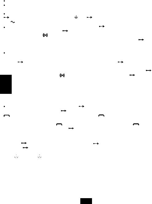
FEHLERSUCHE UND SERVICE FÜR DIE  VIDEO-TÜRSPRECHANLAGE
1.Normalbetriebsmodus,ohne BAT: Die Netzwerk  und + U-LEDs sind grün. Die PROG - und BAT - LEDs sind ausgeschaltet.
2.Normaler Betriebsmodus,bei angeschlossenem BAT: Die LEDs Network  , BAT und + U sind grün.
3. Das System funktioniert nur im Akkubetrieb (die Installation funktioniert bis zur vollständigen Entladung des Akkus): Die LED BAT leuchtet grün, die LEDs und + U sind ausgeschaltet. Überprüfen Sie die Sicherungen an der SCU (FUSE T-1, 6A) und 2x6A vom Netzwerk
  .
.
4.Das System funktioniert mit einer defekten Batterie. Die Netzwerk  , + U-LEDs sind grün, die BAT-LED ist ausgeschaltet. Wechseln Sie die Batterie!
5.Die Außeneinheit funktioniert nicht (die rote LED der Außeneinheit blinkt nicht, die Ruftasten sind nicht beleuchtet):
Die LEDs  , BAT und + U sind grün.Auf der SCU ist die LED VIDEO AUßENEINHEIT rot. Überprüfen Sie die Kontinuität und die Genauigkeit der + U- und GND-Verbindungen von der SCU zum Paneel.
6.Eine Inneneinheit funktioniert nicht (die Tasten sind nicht beleuchtet, wenn kein Bild und Ton anwesend sind): Die LEDs , BAT und + U sind grün. Eine der LEDs OUT1, OUT2 oder OUT3 ist rot. Überprüfen Sie die Kontinuität und Genauigkeit der
+U- oder GND-Verbindungen von der SCU zur Inneneinheit.
7.Des Schloss funktioniert nicht (LCK,LCK): Überprüfen Sie die Genauigkeit der Verbindungen von der SCU zum Schloss.
8.Die Anzeige der Inneneinheiten ist blau (während des Anrufs ist das Inneneinheit blau, es gibt Ton): Überprüfen Sie die Kontinuität und Genauigkeit der Vin-, Vout- und GND-Verbindungen von der Außeneinheit zur Videoinneneinheit während des Anrufs.
9.Die Inneneinheiten werden nicht gerufen, die PROG-LED ist rot: Überprüfen Sie die Kontinuität und die Genauigkeit der C/D-,
+U - und GND-Verbindungen von der Außeneinheit zur Video-Inneneinheit.
10.Die Inneneinheit für Familie 2,Familie 3 oder höhere Adressen kann nicht angerufen werden: die Inneneinheit mit der richtigen Adresse (Wohnungsnummer) im Benutzerhandbuch neu programmieren.
2

INSTALLATION INSTRUCTIONS – |
VIDEO DOOR PHONE KIT |
|
Thank you for choosing the BELLCOME products. We will assist you throughout the entire warranty period. |
|
|
For technical support and assistance you can contact us at ELECTRA Building Communications GmbH |
+43 1 810 20 99, |
|
support@bellcome.com. |
|
|
KIT INSTALLATION. Follow the steps below, in the described order.
 STEP 1. Read the diagrams in this brochure and the technical manuals of the KIT (VPA, VTx, SCU).
 STEP 2. Make the electrical connections to the terminals (ATM, VTM, VTA) and then to the VPA outdoor panel.
 STEP 3. Make the electrical connections of the LCK door lock and LOCK SUPPLY to the terminals of the SCU central unit and, if necessary, the connections to: the EXIT button; AUX additional installations; BAT; Vcam analog video camera.
 STEP 4. AUTHORIZED PERSONNEL!!! READ THE SAFETY INSTRUCTIONS FROM THE MANUAL OF THE SCU CENTRAL
SUPPLY UNIT!!! |
DISCONNECT the fuses and make the L,N, |
|
|
connections to the SCU |
CONNECT the fuses to the |
|||
|
|
|||||||
|
|
|||||||
|
|
|||||||
power network. The |
, S2 LEDs turn on, and S1 turns on only if the battery (12V/max. 42Ah) is connected. |
|||||||
STEP 5.1. PROGRAMMING THE MAIN ENTRANCE PANEL: RFID CARDS/TAGs |
At the SCU, long press (3 sec.) the PROG |
|||||||
button (point 6). The PROG Red LED turns on |
Go to the VPA panel from the main entrance and touch each RFID CARD |
|||||||
to the |
(RFID) area for one second. For each programmed RFID CARD/TAG, the panel issues two beeps. |
|||||||
Follow the same steps for programming all the RFID CARDS/TAGs, for all the residents of the building. |
||||||||
|
Return to the SCU and short press the PROG button. The Red LED turns off. The main panel keeps address 1, which |
|||||||
EN |
is set from the factory and is ready to function. |
|
|
|||||
STEP 5.2. PROGRAMMING THE ADDITIONAL PANEL: NEW ADDRESS and RFID CARDS/TAGs. If the access in the building |
||||||||
|
is made through two entrances, the VPA2 additional panel (point 11) from entrance 2 must be set up with address 2. |
|||||||
|
At SCU 2 long press the PROG button. The PROG Red LED turns on. |
At the VPA2 panel, long touch the Fam.1 key |
||||||
(long confirmation beep), then short touch the Fam.1 key, twice. The panel confirms the storage of address 2 with |
|
||
two short beeps. Continue programming the CARDS/TAGs in the VPA2 panel. |
Each touch of the CARD/TAG to the |
area is |
|
confirmed by the VPA2 with two beeps. |
Return to the SCU2 and short press the PROG button. The Red LED turns off. |
|
|
The VPA2 and VPA1 panels are ready to function, with all the terminals in the building. |
|
||
STEP 6.1 PROGRAMMING THE ADDRESS OF THE Fam.1 TERMINAL. The terminals keep Address 1, which is set by the |
|
||
manufacturer. |
|
|
|
STEP 6.2 PROGRAMMING THE ADDRESS OF THE Fam.2, Fam.3 or more TERMINALS. The terminals for Family 2 will have |
|||
address 2, the terminals for Family 3 will have address 3 and so on for 4, 5 etc. |
|
|
|
Program the new addresses as follows: |
At SCU 1 long press (3 sec.) the PROG button. The PROG Red LED turns on |
|
|
At the terminals for Family 2, long touch the |
key. The terminal confirms with one long beep. Short touch the |
|
|
key twice. Two short beeps are issued. The terminal stores address 2. Continue programming address 3 at Family 3 following
the same steps. Long touch the |
key and after the long beep, short touch the |
key three times. Storage is confirmed |
||||
with three short beeps. |
Return to the SCU and short press the PROG button. The Red LED turns off. The terminals are |
|||||
ready to function. |
|
|
|
|
|
|
RECOMMENDED CABLES (point 1) Maintain the same wire colors for the same connections. |
||||||
1) Max. 75 ml |
4 x 0.5 mm2 (H03VV-F4G 0.5) |
3) Max. 250 ml |
UTP cat5e (AWG24) or UTP cat6e (AWG23) |
|||
2) Max. 150 ml |
4 x 0.75 mm2 (H05VV-F4G 0.75) |
|
|
|
||
Out of electrical safety reasons, we recommend installing a grounding cable (minimum 1.00 mm2 – Green/Yellow) from the
panel (VPM) to the |
|
|
central unit (SCU). |
|
|
||
|
|
||
|
|
DETAILED PRODUCT CODES
 VPA - advanced video outdoor panel; Product codes: 1Fam.VPA.1S(F)R02.xxy04; 2Fam.VPA.2S(F)R02.xxy04; 3Fam.VPA.3S(F)R02.xxy04; 5Fam.VPA.5S(F)R02.xxy04 (S= Surface mounting, F= Flush mounting, R= RFID CARD/TAG access)
  RFID access CARD/TAG (secured at reading and copying). They are stored and can be deleted from the VPM.
 ATM - smart+ audio terminal; Product code: ATM.0S402.xxy04
 VTM - smart+ 3.5” video terminal; Product code: VTM.3S402.xxy04
 VTM/VTA - smart+/advanced 7” video terminal; Product codes: VTM.7S402.xxy04/ VTA.7S902.xxy04
  VCB – Video connection box (1 video input/4 video outputs - 4 Fam.); Product code: VCB.4DN02.xxy04
1

 VSB – Video selection box; Product code: VSB.4DN02.xxy04 (4 video inputs/1 video output)
 SCU – Central supply unit for 1 Fam; Product code: SCU.VDR02.xxy14 (110-230 Va.c., 50 Hz / 13,5 Vd.c.-2 Ad.c.). Central supply unit for 3 Fam; Product code: SCU.VDR02.xxy34 (110-230 Va.c., 50 Hz / 13,5 Vd.c.-2 Ad.c.).
 PSU – Additional supply unit; Product code: PSU.VDR02.xxy04 (110-230 Va.c., 50 Hz / 13,5 Vd.c.-2 Ad.c.), necessary when, due to various reasons, the supply voltage (+U, GND) at the hubs of the terminals drops below 12V.
 Vcam – Additional video camera connection, analogic 1Vv-v, PAL
 LCK/LCK – Connection of an alternating current lock (max.5Aa.c./24Va.c.), a direct current lock (max.3Ad.c./24Vd.c.) or an electromagnetic lock (max.3Ad.c./ 24Vd.c.)
 LOCK SUPPLY – Connection of the door lock supply (max. 24 Va.c./24Vd.c.). A direct current lock of max. 0.6Ad.c./12Vd.c. can be powered directly from the SCU by making the connections at the +U - GND connections of the VIDEO DOOR PANEL connector.
 NO/NC – Setting of the door lock functioning. NO-Normal Open - LCK relay normal open; NC-Normal Closed - LCK relay normal closed.
 EXIT/EXIT – Connection of EXIT button (mounted inside the building)
 AUX1/AUX2 – Connection of additional installations – auto gate, garage door, outdoor lighting etc. (point 4)
 + BAT/- BAT – Connection of rechargeable battery
 DBL1/DBL2 – Connection of entrance doorbell (apartment doorbell)
  GONG1/GONG2 – Connection of distance call doorbell (GONG)
PARALLEL CONNECTION OF THE ADDITIONAL TERMINALS (See the diagram from point 10) |
EN |
|
Inside the residence you can install TL additional terminals (ATM/VTM 3.5”/ VTM 7”/ VTA 7”) using the same type |
||
|
||
of cable, for the same connections (+U, C/D, GND, Vin/Vout). All the terminals in one apartment will have the |
|
|
address of the main terminal. For Fam.1 the terminals have address 1 set by the producer. For Fam. 2, 3 |
|
|
(Fam. 4, 5 or more), program the terminals with addresses 2, 3 (or 4, 5 etc.). See Step 6.2. |
|
PARALLEL CONNECTION OF TWO OUTDOOR PANELS (See the diagram from point 11)
If the building has multiple entrances, you can install VPA outdoor panels with their own SCU central supply unit, which will command its own gate. The VPA1 main outdoor panel keeps address 1, set by the manufacturer and only the RFID access cards/tags will be programmed at the VPA1 (see Step 5.1). The VPA2 additional panel is programmed with address 2 and with the RFID access cards/tags (see Step 5.2).
TROUBLESHOOTING AND SERVICE FOR THE  VIDEO DOOR PHONE SYSTEM
1.Normal functioning mode, without BAT: the and +U LEDs are green. The PROG and BAT LEDs are turned off.
2.Normal functioning mode, with BAT connected: the  , BAT and +U LEDs are green.
3. The system functions only on battery (the installation functions correctly until the full discharge of the battery): the BAT LED is green, the and +U LEDs are turned off. Check the fuses on the SCU (FUSE T-1, 6A) and 2x6A from the network
 .
.
4.The system functions with a broken battery. The  , +U LEDs are green, the BAT LED is turned off. Change the battery!
5.The outdoor panel does not function (the red LED from the outdoor panel does not blink, the call keys are not backlighted):
The , BAT and +U LEDs are green. At the SCU, the VIDEO DOOR PANEL LED is red. Check the continuity and the accuracy of the +U and GND connections from the SCU to the panel.
6.A terminal does not function (the keys are not backlighted when touched, there is no image and sound): the  , BAT and +U LEDs are green. One of the OUT1, OUT2 or OUT3 LEDs is red. Check the continuity and accuracy of the +U or GND connections from the SCU to the terminal.
7.The lock does not function (LCK, LCK): check the accuracy of the connections from the SCU to the lock.
8.The display of the terminal is blue (during call, the terminal is blue, there is sound): check the continuity and accuracy of the Vin, Vout and GND connections from the outdoor panel to the video terminal.
9.The terminals are not called, the PROG LED is red: check the continuity and the accuracy of the C/D, +U and GND connections from the outdoor panel to the video terminal.
10.The terminal for Family 2, Family 3 or with higher addresses cannot be called (The Family 1 terminal is always called): reprogram the terminal with the correct address (the number of the apartment) according to the procedure in the user manual
of the terminal.
2
INSTRUCCIONES PARA LA INSTALACIÓN - KIT VÍDEO INTERFONO 
Estimado Cliente, gracias por haber elegido los productos BELLCOME. Nosotros vamos a estar junto a usted durante todo el período de garantía. Para sporte técnico y asesoramiento nos puede contactar en ELECTRA Building Communications GmbH 
 +43 1 810 20 99, support@bellcome.com.
LA INSTALACIÓN DEL KIT. Siga los pasos de abajo, en el orden descrito a continuación.
 PASO 1. Lea los esquemas de este folleto y los libros técnicos del KIT (VPA, VTX, SCU).
PASO 2. Haga las conexiones eléctricas en los terminales (ATM, VTM, VTA) y luego al panel exterior VPA.
PASO 3. Haga las conexiones de la cerradura LCK y de la alimentación de la cerradura LOCK SUPPLY a las bornas de la unidad central SCU y, en su caso, las conexiones para: botón EXIT; instalaciones auxiliares AUX; BAT; cámara vídeo analógica Vcam.
PASO 4. ¡¡¡PERSONALAUTORIZADO!!! LEA LAS INSTRUCCIONES DE SEGURIDAD DEL MANUAL DE LA UNIDAD CENTRAL SCU!!!
|
DESACOPLE los fusibles y haga las conexiones L,N, |
|
|
a SCU |
ACOPLE los fusibles a la red. A SCU se encienden los |
|||||||
|
|
|
||||||||||
|
|
|
||||||||||
|
|
|
||||||||||
LEDs |
, S2, y S1 solamente si tiene conectada la batería (12V/max. 42Ah). |
|
|
|
|
|||||||
PASO 5.1. PROGRAMACIÓN PANEL ENTRADA PRINCIPAL: TARJETAS RFID |
A SCU apretar largamente (3 seg.) el botón |
|||||||||||
PROG (punto 6). El LED rojo PROG se enciende |
Vaya al panel VPA de la entrada principal y toque por un segundo |
|||||||||||
cada TARJETA RFID de la zona |
(RFID). Para cada TARJETA RFID programada,el panel emite dos beeps. |
|
||||||||||
Continúe de este modo hasta que programe todas las TARJETAS RFID, para todos los habitantes del edificio |
Vuelva |
|||||||||||
a SCU y apriete cortamente el botón PROG. El LED rojo se apaga. El Panel principal queda con la dirección 1 ajustada |
||||||||||||
desde la fábrica y está listo para funcionar. |
|
|
|
|
|
|
|
|
|
|||
PASO 5.2. PROGRAMACIÓN PANEL ADICIONAL: LA NUEVA DIRECCIÓN y TARJETAS RFID. Si el acceso en el edificio se |
||||||||||||
hace por medio de dos entradas, el panel adicional VPA2 (punto 11) de la entrada 2 debe ser ajustado con la |
|
|||||||||||
dirección 2. |
A SCU 2 apriete largamente el botón PROG. El LED PROG rojo se enciende. |
Al panel VPA2 apriete largamente |
||||||||||
la tecla Fam.1 (beep largo de confirmación), luego apriete cortamente dos veces la tecla Fam.1. El panel confirma con dos |
||||||||||||
beeps cortos |
la memorización de la dirección 2. Continúe con la programación de las TARJETAS en el panel VPA2 |
|||||||||||
|
Cada toque de la TARJETA de la zona |
va a ser confirmado por VPA2 mediante dos beeps. |
Volver a SCU2 y apretar |
|||||||||
ES |
cortamente el botón PROG. El LED rojo se apaga. El panel VPA2 y VPA1 están listos para funcionar, con todos los |
|||||||||||
terminales del edificio. |
|
|
|
|
|
|
|
|
|
|
||
|
PASO 6.1 PROGRAMACIÓN DE LA DIRECCIÓN TERMINAL Familia 1. Los terminales quedan con la Dirección 1 ajustada por |
|||||||||||
el productor.
 PASO 6.2 PROGRAMACIÓN DE LA DIRECCIÓN TERMINAL Familia 2,Familia 3 o más.Los terminales de la Familia 2 van a tener la dirección 2, los terminales de la Familia 3 van a tener la dirección 3 y así sucesivamente hasta 4, 5 etc.
Programe las nuevas direcciones de la siguiente manera: |
En la SCU 1, mantenga presionado largamente (3 seg.) |
||
el botón PROG. El LED rojo PROG se enciende |
En los Terminales de la Familia 2, mantenga presionada largamente la tecla |
||
. El terminal confirma con un beep largo. Presione cortamente la tecla |
dos veces. Se escuchan dos beeps cortos. |
||
El terminal ha memorizado la dirección 2. Continúe de la misma manera con la programación de la dirección 3 en la Familia 3.
Mantenga presionada largamente la tecla |
y después del beep largo, presione brevemente la tecla |
tres veces. |
|||
La memorización se confirma con tres beeps cortos. |
Volver a SCU y apretar cortamente el botón PROG. |
|
|||
El LED rojo se apaga. Los terminales están listos para funcionar. |
|
|
|||
CABLES RECOMANDADOS (punto 1) Mantenga los mismos colores de hilo para las mismas conexiones. |
|
||||
1) Max. 75 ml |
4 x 0.5 mm2 (H03VV-F4G 0.5) |
3) Max. 250 ml |
UTP cat5e (AWG24) o UTP cat6e (AWG23) |
||
2) Max. 150 ml |
4 x 0,75 mm2 (H05VV-F4G 0,75) |
|
|
|
|
Por motivos de seguridad eléctrica, recomendamos instalar un cable de conexión a tierra (mínimo 1,00 mm2 - verde / amarillo) desde el  panel (VPA) al
  de la unidad central (SCU).
SIGNIFICADO DE LA CODIFICACIÓN DE LOS PRODUCTOS.
 VPAPanel exterior video smart; Código de productos: 1Fam.VPA.1S (F) R02.xxy04; 2Fam.VPA.2S (F) R02.xxy04; 3Fam.VPA.3S (F) R02.xxy04; 5Fam.VPA.5S (F) R02.xxy04 (S = Montaje en superficie, F = Montaje enterrado, R = Acceso a TARJETA RFID)
 TARJETA de acceso RFID (Seguro para lectura y copia). Se memorizan y se pueden borrar en APM o VPM.
 ATM - Terminal audio smart+; Código de producto: ATM.0S402.xxy04
 VTM – Terminal video 3.5 "smart+ Código de producto: VTM.3S402.xxy04,
 VTM / VTA - Terminal video 7"smart+ / advanced; Código de productos: VTM.7S402.xxy04 / VTA.7S902.xxy04
 VCB - Dosis de derivación video (1 entrada video / 4 salidas de video-4 Fam); Código de producto: VCB.4DN02.xxy04
1
 Loading...