

Bellcome smart Audio, smart 3.5 Video, smart 7 Video, advanced 7 Video operation manual
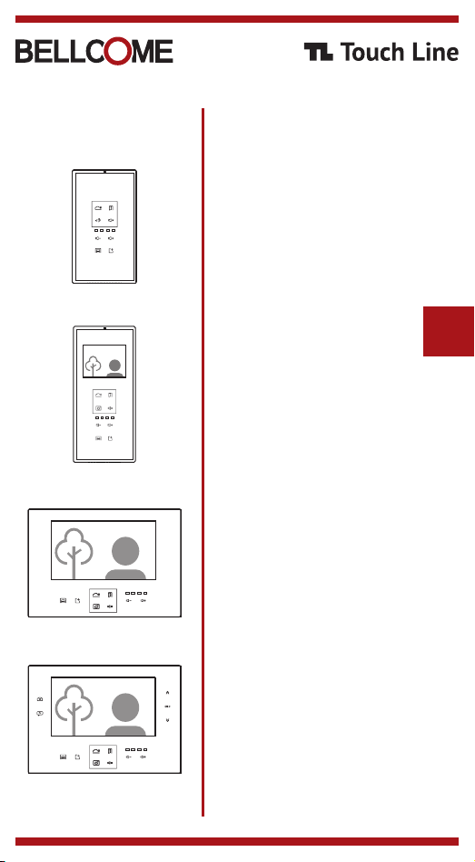
smart Audio
smart 3.5" Video
smart 7" Video
advanced 7" Video
USER MANUAL
Audio & Video terminals
door system4 WIRE
EN

Contents
0
Safety instructions
1
Description of the Touch Line terminals
2
Recommended cables.
3
Installation of the Touch Line terminals.
Programming the addresses of the
4
Touch Line terminals
Safety instructions
1
DO NOT power the product at 110 – 230 Va.c.!
DO NOT hit the glass screen with hard objects!
If the glass screen is broken, DO NOT touch the product.
Protect the products against lime and dust during renovation activities.
Description of the Touch Line terminals
2
Settings of the Touch Line terminals
5
Use of the Touch Line terminals
6
Use of the Touch Line outdoor panels
7
Maintenance
8
Declaration of conformity. Warranty.
9
EN
1
smart audio terminal
ATM.0S403.BLB(W)04
ABS case + chemically toughened glass
170x96x22 mm
0,3 kg
o o
0 C … + 45 C
IP31
U = 12...14 Vd.c.
smart video terminal
VTM.7S403.BLB(W)04
ABS case + chemically toughened glass ABS case + chemically toughened glass
smart video terminal
VTM.3S403.BLB(W)04
ABS case + chemically toughened glass
3.5" LCD TFT 320 (RGB) x 240
212x96x22 mm
0,4 kg
o o
0 C … + 45 C
IP31
U = 12...14 Vd.c.
advanced video terminal
VTA.7S903.BLB(W)04
7“ LCD, TFT, 800 x 3 (RGB) x 480
162x227x20 mm
0,8 kg
o o
0 C … + 45 C
IP31
U = 12...14 Vd.c.
* B = Black; W = White
7“ LCD, TFT, 800 x 3 (RGB) x 480
162x227x20 mm
0,8 kg
o o
0 C … + 45 C
IP31
U = 12...14 Vd.c.

Recommended cables. Installation of the Touch Line terminals.
3
Recommended cables
3.1
4 WIRE Installation (standard)
4 wires x 0.5 mm (type H03VV-F4G 0.5) for maximum 60 ml or another type of
equivalent cable;
4 wires x 0.75 mm (type H05VV-F4G 0.75) for maximum 150 ml or another type of
equivalent cable;
Generally, any type of 4-wire cable with a 0.5 mm section is accepted. Telephone cables
type TCYY - 2x2x0.5-24 AWG (max. 30 ml); TCYY -3x2x0.5-24 AWG (max. 50 ml);
TCYY - 4x2x0.5-24 AWG (max. 50 ml) can also be used.
Note: If the cable has more than 4 wires, the additional wires will be connected the same
as in the case of an UTP cable.
The +14 and GND connections are equally supplemented with the additional wires.
2
2
SCU/ VCB
+14
C/D
GND
Vout
6mm
20-25mm
20-25mm
Audio-Video
Terminal
+14
C/D
GND
Vin
6mm
UTP cable Installation
For distances between 150 ml and 250 ml it is mandatory to use the twisted pair
cable type UTP/ FTP cat5e (AWG24) or UTP/ FTP cat6 (AWG23).
The connection of the audio-video terminals to the installation is done with a RJ45
connector or with screw connectors.
RJ45 connections
(EIA 568B)
1. White-Orange
2. Orange
3. White-Green
4. Blue
5. White-Blue
6. Green
7. White-Brown
8. Brown
1
8
Screw connections
25-30mm
6mm
+14
C/D
GND
Vin
EN
2
+14
+14
DBL1
DBL2
GNG1
GNG2
Vout
Line IN Line OUT
Additional
terminal
Main
terminal
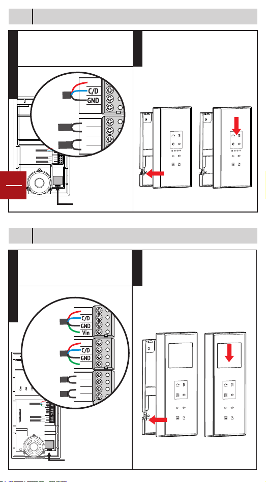
Installation of the audio terminal - ATM.0S403.BLB(W)4
+14
IN/OUT
Main
terminal
DBL
DBL
GNG1
GNG2
GND
3.2
1. Fasten the back case on the wall.
Recommended height H=135cm
STEP 1
2. Fasten the connectors on the back case.
STEP 2
+14
Line IN
GND
DBL1
DBL2
GONG1
GONG2
Make the connections
EN
3
3.3
Installation of the 3.5” video terminal - VTM.3S403.BLB(W)4
in the connector
fastened on the
back case.
RJ45 connection
1. Place the terminal front case with the
fastened connectors over the back case.
STEP 3
2. Pull the terminal down until it interlocks.
2
1
1. Fasten the back case on the wall.
Recommended height H=135cm
STEP 1
2. Fasten the connectors on the back case.
STEP 2
+14
Line IN
Line OUT
+14
Vout
DBL1
DBL2
Make the connections
GONG1
GONG2
in the connector
fastened on the
back case.
RJ45 connection
1. Place the terminal front case with the
fastened connectors over the back case.
STEP 3
2. Pull the terminal down until it interlocks.
2
1
 Loading...