

Bellcome CU.VDR02.BLG14, SCU.VDR02.BLG34 operation manual
S1: 13.5V, 2.5A
S2 (BAT): 12V/max. 42Ah
S1: 13.5V, 2.5A
S1: 13.5V, 2.5A
S2 (BAT): 12V/max. 42Ah
S2 (BAT): 12V/max. 42Ah
4 Wires
CENTRAL SUPPLY AND COMMAND UNIT for
TL 4-WIRE video doorphone systems
User manual
3
SCU.VDR02.BLG34SCU.VDR02.BLG14
EN
Contents
0
Safety instructions
1
Description of the central unit
2
Functions of the central unit. Troubleshooting and service for the TL video doorphone system.
3
Recommended cables. Installation.
4
Setting the programming mode for the Touch Line video door phone system
5
Warranty
6
EN
1
1
1. ATTENTION! The installation, maintenance and connection of the central unit (SCU) to the 110 V/ 230 V – 50 Hz/ 60 Hz power network
is done only by AUTHORIZED PERSONNEL!
2. ATTENTION! It is mandatory to use a 3 x 0,75 cable and 2 automatic fuses (6A) to power the central unit (SCU) from the 110V/230V
- 50Hz/60Hz power network.
3. IMPORTANT! The S1 fuses remain disconnected when the L, N, connections are made to the SCU, and when the L1, N1 connections
are made to the S1 fuses. After the connections are made, the protection lids of the connections are mounted.
4. ATTENTION! The S1 safety fuses must be disconnected during the mounting, connection and service to the central unit (SCU).
5. ATTENTION! DO NOT DISMANTLE THE FRONT LID OF THE CENTRAL UNIT (SCU)! RISK OF ELECTRIC SHOCK! Only the protection
cases of the connections can be dismantled during mounting or service.
6. DO NOT TOUCH the metallic parts of the wires or the connection terminals of the central unit (SCU) or of the fuses. First, you have to
disconnect the 6A fuses ( ) from the power network and then you can work with the central unit (SCU).POWER OFF
4-WIRE SCU safety instructions
7. ATTENTION! Do not supply components of the installation separately (outdoor panel, terminals etc.) at voltage higher than 14 Vd.c.
or directly from the network (230 V/ 50 Hz or 110 V/ 60 Hz). RISK OF ELECTRIC SHOCK and damage of the installation.
8. PAY ATTENTION at the polarity of the BAT battery connections (max. 42 Ah/ 12 Vd.c.) when connecting it to the central unit (SCU).
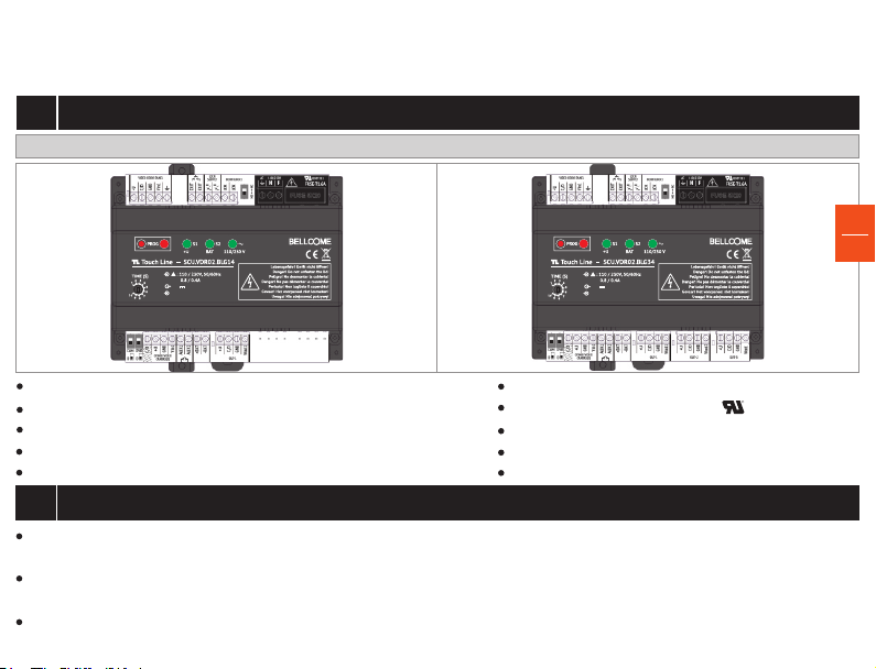
The electrical and mechanical features of the 4-WIRE SCU central unit
2
SCU.VDR02.BLG14 SCU.VDR02.BLG34
S1: 13.5V, 2.5A
S1: 13.5V, 2.5A
S2 (BAT): 12V/max. 42Ah
S2 (BAT): 12V/max. 42Ah
Central supply unit
S1: 13.5V, 2.5A
S2 (BAT): 12V/max. 42Ah
3
EN
2
Power supply voltage: 110/ 230 Va.c. - 50/ 60 Hz
Output voltage: 13.5 Vd.c. +/- 5% max. 2.5Ad.c.
Overload protection for the input and output current
Network overvoltage protection
EMI filter (electromagnetic compatibility)
Description of the 4-WIRE SCU central unit
2.1
Case: PA6.6 + FS 10% (fireproof)
UL certified printed circuit board
R
Dimensions: 130 x 141 x 73 mm
Weight: 0.4 Kg
Operating temperature range: 0 - 40 C
o o
E307311
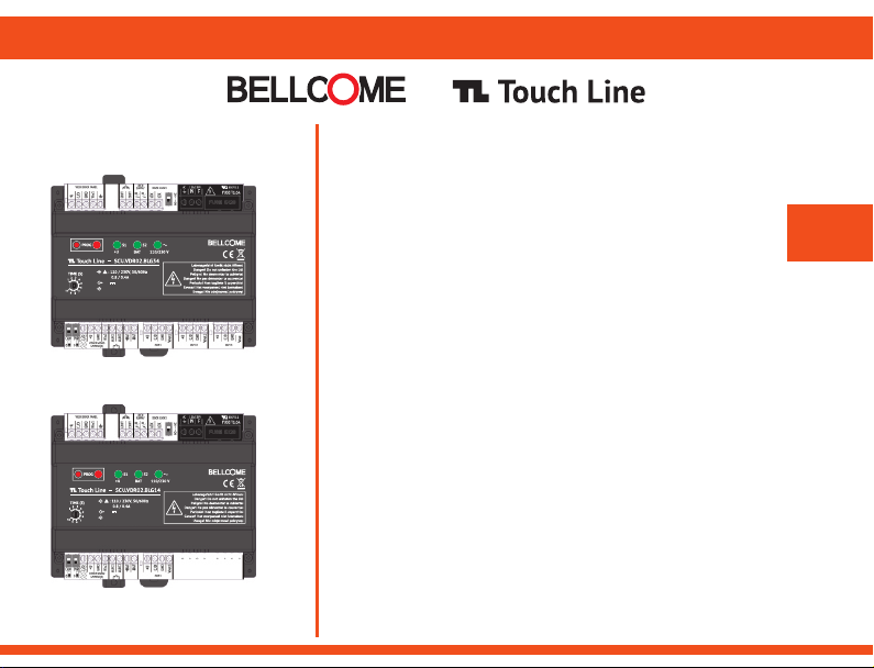
For the video door phone systems with 1 Family, the central supply unit with 1 OUTPUT will be used, model
SCU.VDR02.BLG14, which only has output OUT1 for Family 1.
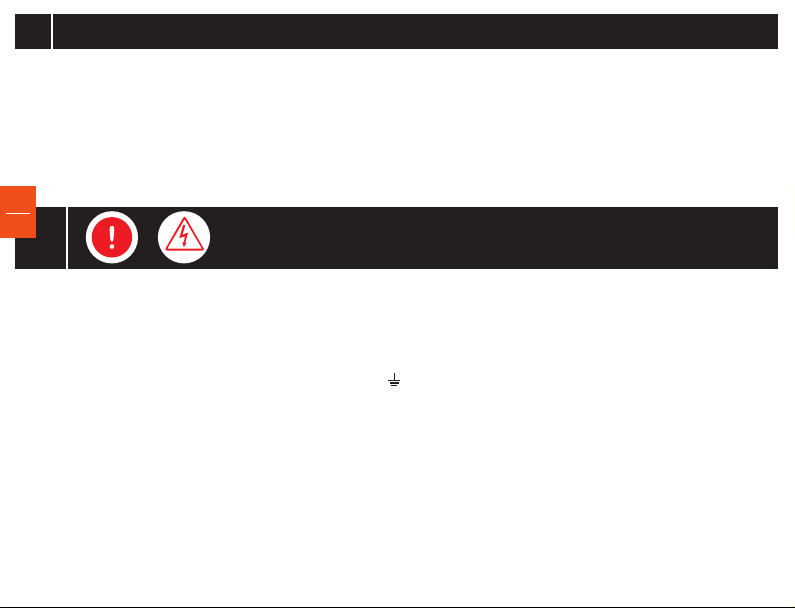
For the video door phone systems with max. 3 Families, the central supply unit with 3 OUTPUTS will be used, model
SCU.VDR02.BLG34 (OUT1-Family 1, OUT2-Family 2, OUT3-Family 3).
For video door phone systems with more than 3 Families, for connecting the terminals of the families to the
outdoor panel, SCU.VDR02.BLG14 will be used and one or two video distributors, type VCB.4DN02.BLG04.
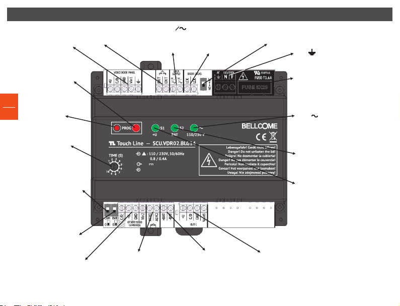
The distribution of the connections for the SCU.VDR02.BLG14 CENTRAL SUPPLY and COMMAND UNIT
VIDEO DOOR PANEL,
Connection of the
cable from the
outdoor panel
LED PROG red, the panels
and terminals are in
programming mode
PROG Programming
EN
mode setting/resetting
3
button
TIME Lock opening time
adjustment (max. 10s)
CAM is switched to position 1
for connecting the
OTHER VIDEO CAMERA to the
SCU and visualization on
the terminal
DVR is switched to position
1 for permanent image
recording from the
OTHER VIDEO CAMERA,
on a DVR
OTHER VIDEO CAMERA
Analog, PAL, CMOS/ CCD,
1 Vp.p. with adapting
video transformer
EXIT Connection
of exit button
1 1
AUX1,AUX2
Connection of
additional installations:
auto gate, garage,
outdoor lights etc. (relay contact)
LOCK SUPPLY
=
Separate lock supply,
max 24 Vd.c/24Va.c.
S1: 13.5V, 2.5A
S1: 13.5V, 2.5A
S2 (BAT): 12V/max. 42Ah
S2 (BAT): 12V/max. 42Ah
LCK Lock connection
Max. 3A/24Vd.c.
Max. 5A/24Va.c.
+BAT, -BAT
Connection of 12Vd.c.,
max. 42Ah
rechargeable battery
NO-Normal open – LCK relay, normal open
NC-Normal Closed – LCK relay, normal closed
L,N, Connection to the
110/ 230 Va.c. - 50/ 60 Hz network
FUSE, Electrical network fuse
1.6 Aa.c.
LED Green, presence of
110/ 230 Va.c. 50/ 60 Hz voltage
LED BAT Green, max. 42Ah – 12Vd.c.
rechargeable battery,
connected to the SCU
LED +U green, +13.5 Vd.c. +/-5%
voltage presence
OUT1
Connection of the cable
to the Fam. 1 terminal
or VCB
 Loading...