

Bellcome KIT VIDEO DOOR PHONE 3.5” User manual [ml]
3.5” VIDEOTÜRSPRECHANLAGEN SET
DE
Benutzerhandbuch
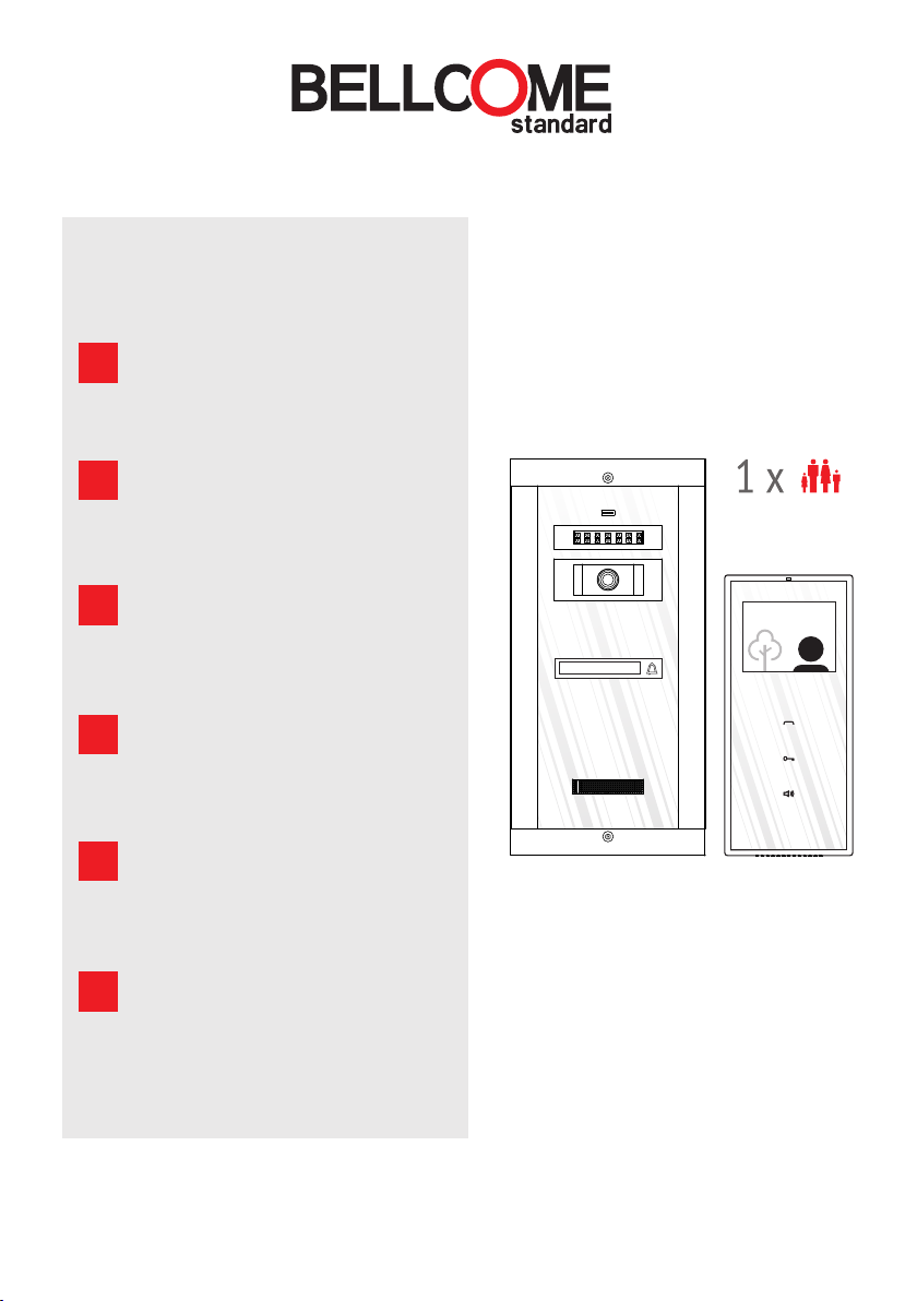
1 Familie
KIT VIDEO DOOR PHONE, 3.5”
EN
User manual
1 Family
KIT INTERPHONE VIDÉO, 3.5”
FR
Manuel d'utilisation
1 Famille
KIT VIDEO-CITOFONO, 3.5”
IT
Il manuale dell'utente
1 Famiglia
KIT VIDEOINTERFON, 3.5”
NL
Gebruikershandleiding
1 Gezin
ZESTAW WIDEODOMOFON 3.5”
PL
Instrukcja obsługi
1 Rodzin
Name 1
www.bellcome.com
0
DE
INHALT
CONTENTS
EN
SOMMAIRE
FR
CONTENUTO
IT
INHOUD
NL
SPIS TREŚCI
PL
DE
Eigenschaften & Inhalt des sets
EN
1,2
Blockdiagramme
3
4
Features & Kit components
FR
Fonctions Contenu du kit &
DE
EN
Block diagrams
FR
Schémas-bloc
DE
Sicherheitshinweise
EN
Safety instructions
FR
Consignes de sécurité
DE
5
6
7
Installation
EN
Installation
FR
Installation
DE
Benutzung der videotürsprechanlage
EN
Use of the video door phone
FR
Utilisation de l'interphone vidéo
DE
Fehlerdiagnose
EN
Troubleshooting
FR
Dépannage
DE
Instandhaltung & Garantie
EN
8,9
Maintenance & Warranty
FR
Entretien & Garantie
pg. 1...5
pg. 1...5
pg. 1...5
pg. 5
pg. 5
pg. 5
pg. 6 pg. 9
pg. 7
pg. 8
pg. 12...17
pg. 12...17
pg. 12...17
pg. 18...22
pg. 25...29
pg. 32...36
pg. 23...24
pg. 30...31
pg. 37...38
pg. 24
pg. 31
pg. 38
IT
& Funzioni Componenti del kit
NL
& Functies Kit samenstelling
PL
& Funkcje Składniki zestawu
IT
Diagramma blocco
NL
Blokschema's
PL
Schemat blokowy
IT
Istruzioni di sicurezza
NL
Veiligheidsinstructies
PL
Zasady bezpieczeństwa
IT
Installazione
NL
Installatie
PL
Instalowanie
IT
L'utilizzo del videocitofono
NL
Het gebruik van video-intercom
PL
Używanie wideodomofonu
IT
Riparazione
NL
Problemen verhelpen
PL
Rozwiązywanie problemów
IT
Manutenzione & Garanzia
NL
Onderhoud & Garantie
PL
Utrzymanie & Gwarancja
pg. 1...5
pg. 1...5
pg. 1...5
pg. 5
pg. 5
pg. 5
pg. 10
pg. 11
pg. 12...17
pg. 12...17
pg. 12...17
pg. 39...43
pg. 46...50
pg. 53...57
pg. 44...45
pg. 51...52
pg. 58...59
pg. 45
pg. 52
pg. 59
Maximale Spannung für eine korrekte Installation/
Verkabelung.
Maximum attention for correct installation/
wire connection.
Grande attention à l'installation et à la connexion
correcte des fils.
Attenzione massima per la correttezza del
montaggio/della connessione dei fili.
Maximale aandacht voor een juiste installatie/
aansluiting draden.
Maksymalną uwagę należy zwrócić na prawidłowe
zainstalowanie / podłączenia przewodów
Gefahr durch elektrischen Schlag!
Autorisierte Personen erforderlich!
Risk of electric shock!
Authorized personnel required!
Danger de choc électrique ! Toute intervention sera faite
uniquement par du personnel autorisé !
Pericolo shock elettrico! L'intervento viene eseguito soltanto
da personale autorizzato!
Risico op elektrische schok ! Laat alleen uitvoeren door
bevoegd personeel!
Ryzyko porażenia prądem! Obsługa jest wykonywana
wyłącznie przez autoryzowany personel!
DE
EIGENSCHAFTEN
EN
FEATURES
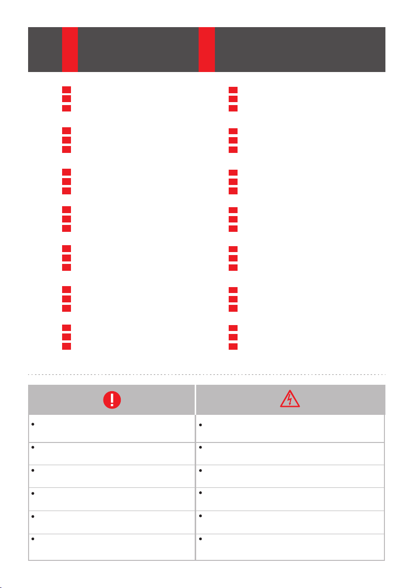
1
1.
Ruf
Call
Appel
Chiamata
Oproep
Połaczenie
2.
Video(3.5”) + Antwort
Video(3.5”) + Answer
Affichage vidéo (3.5”) + Réponse
Video(3.5”) + Risposta
Video (3.5”) + Antwoorden
Wideo (3.5”) + Odpowiedz
3.
Freisprechen
Hands-free talk
Communication mains-libres
Conversazione senza mani
Handsfree gesprek
Rozmowa hands-free
FONCTIONS
FR
IT
NL
PL
FUNZIONI
FUNCTIES
FUNKCJE
4.
Zugangsgewährung
Access granting
Contrôle d'accès
Concedere accesso
Toegang geven
Przyznanie dostepu
5.
Video- & Audioüberwachung
Video & Audio monitoring
Surveillance vidéo et audio
Monitoraggio video & audio
Video- en audio bewaking
Monitoring wideo & audio
1
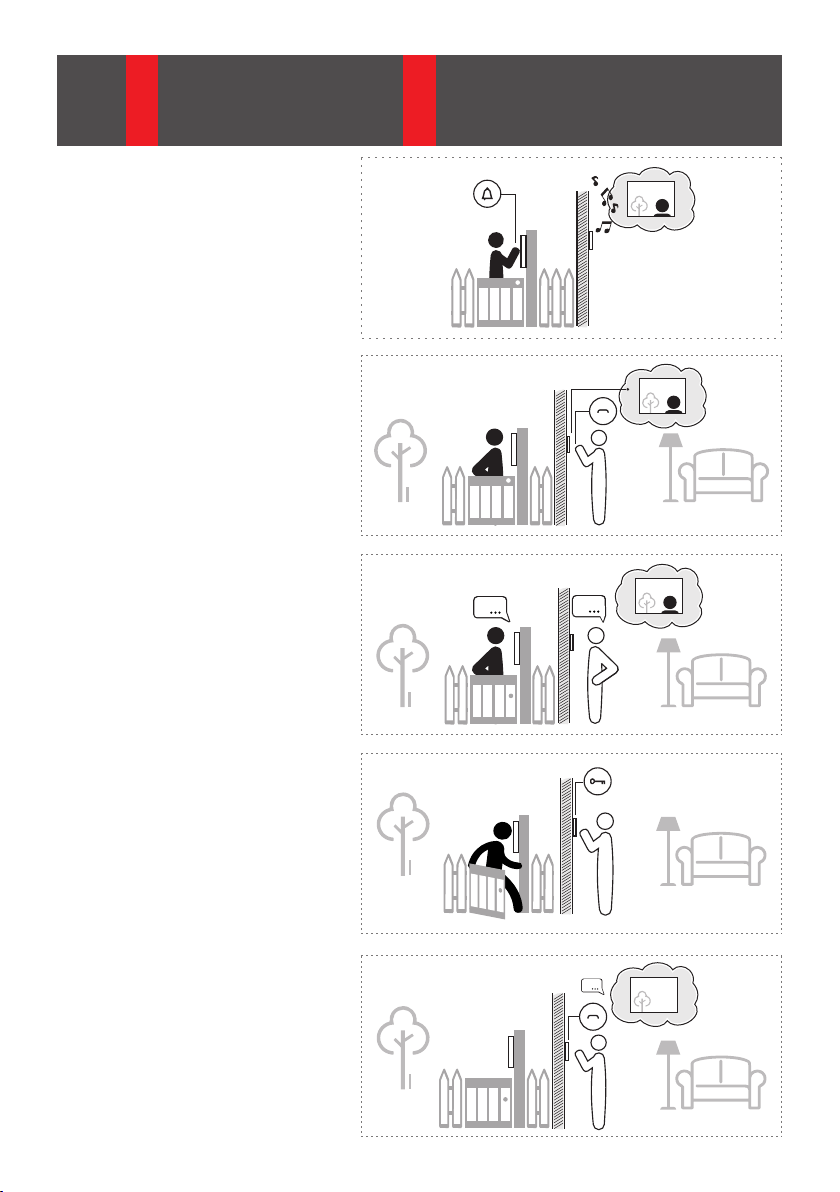
6.
Lautstärke
Volume levels
Volume réglable
Livelli di volume
Volume niveaus
Poziom głośności
7.
Einstellen der Anrufdauer
Setting the ringing duration
Durée de la sonnerie réglable
Sciegliere la durata della chiamata
De duur van de beltoon instellen
Ustawianie trwania połączenia
8.
Mehrere Klingeltöne
Multiple ringtones
Plusieurs sonneries
Più suonerie di chiamata
Meerdere beltonen
Więcej dzwonków
1 7MUTE
5 sec
x
1
2
5 sec
x
5 sec
x
3
1 min
x
5
x
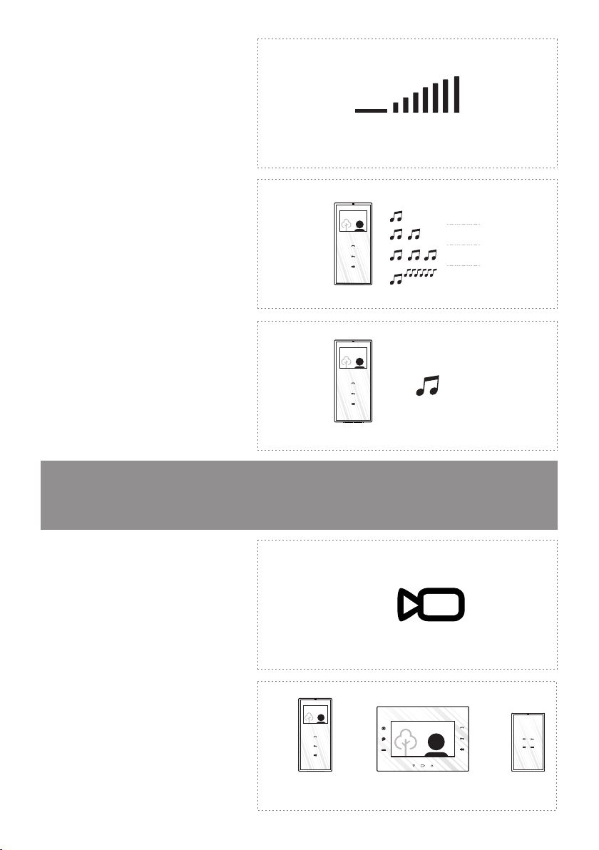
Optionale Funktionen
Optional features
Fonctions optionnelles
Zusätzliche Videokameras
9.
Additional video cameras
Caméras vidéo supplémentaires
Camere video adizionali
Extra videocamera's
Dodatkowe kamery wideo
10.
Zusätzliche Inneneinheiten
Additional terminals
Postes intérieurs supplémentaires
Terminale adizionale
Aanvullende terminals
Dodatkowe terminale
Funzioni opzionali
Optionele functies
Funkcje opcjonalne
1
x
1
x
x
1
2
ok
video 7”
3
x
audiovideo 3.5”
2
INHALT DES SETS
DE
KIT COMPONENTS
EN
CONTENU DU KIT
FR
COMPONENTI DEL KIT
IT
KIT SAMENSTELLING
NL
SKŁADNIKI ZESTAWU
PL
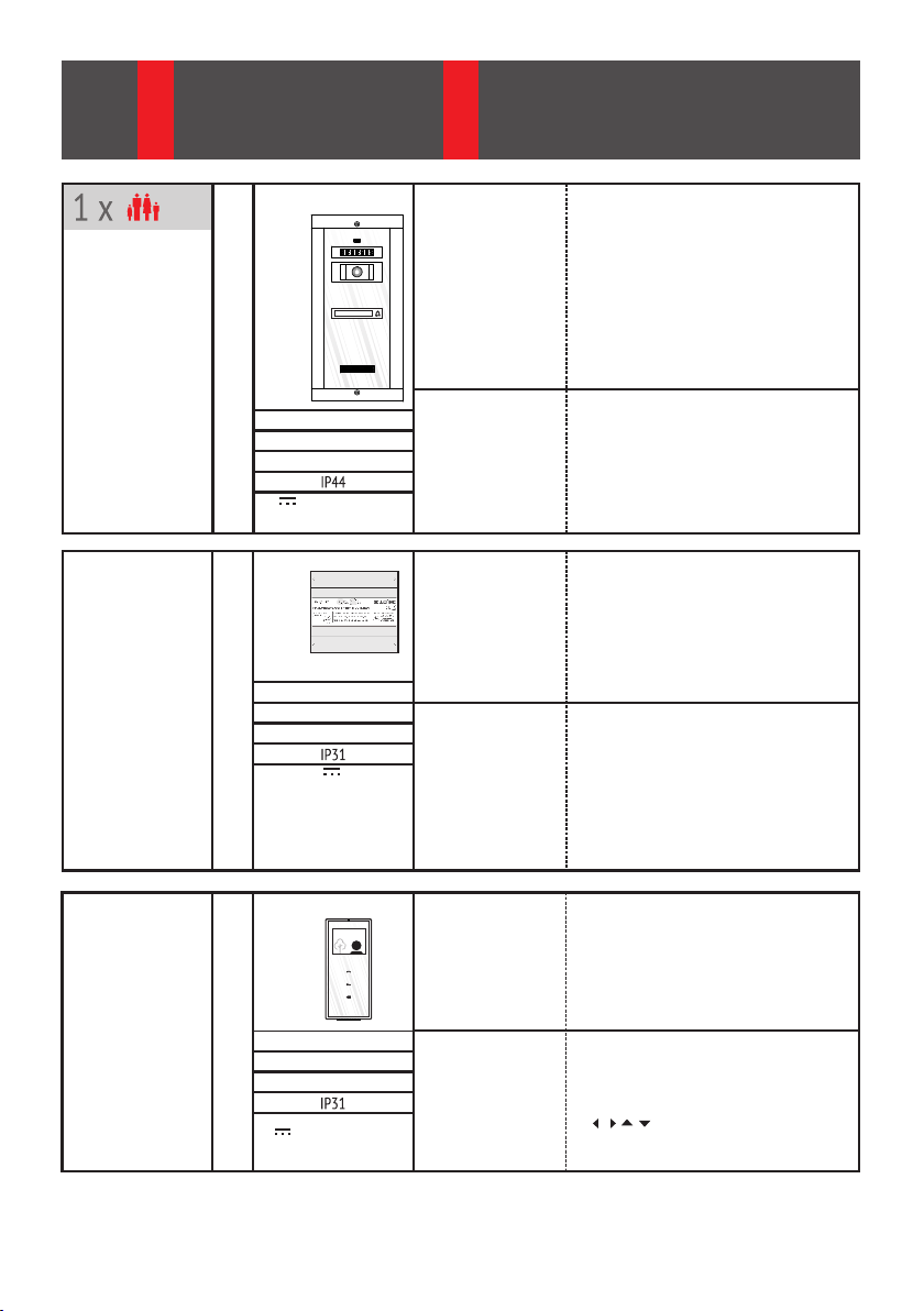
Außeneinheit
Outdoor panel
Platine de rue
Pannello esterno
Buitenpaneel
Panel zewnetrzny
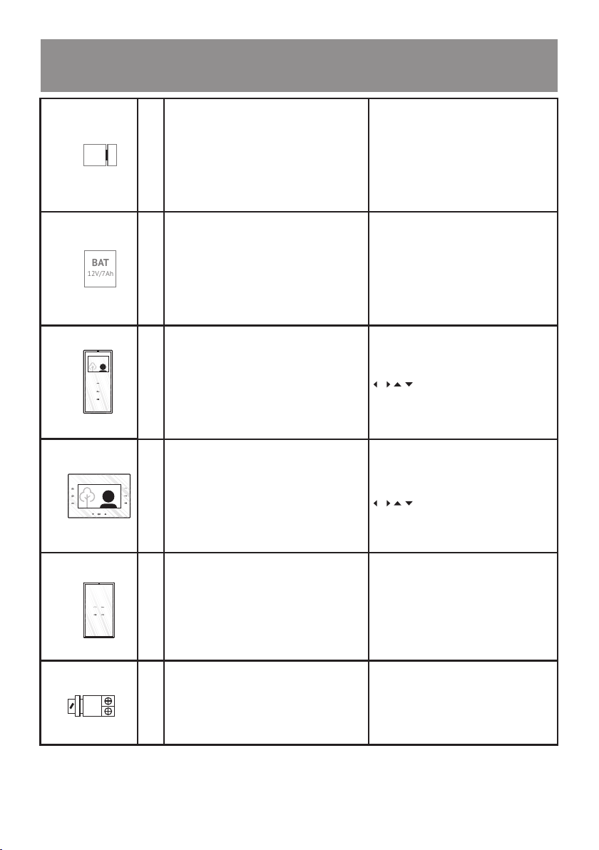
Stromversorgungseinheit
Central unit
Unité centrale
Unità centrale
Centrale eenheid
Jednostka Centralna
VPT
1 x
294 x 144 x 53 mm
1,52 kg
o o
- 30 C … + 60 C
12 … 14 Vd.c.
v
1 x
130 x 141 x 73 mm
SCU
0,4 kg
o o
0 C … + 45 C
14 V- GND : 14 Vd.c./2 Ad.c.
Uv - GNV : 14 Vd.c./0.5 Ad.c.
Vcam - GND : 12 Vd.c./0.4 Ad.c.
Gehäuse
Case
Name 1
v
Carcasse
Scatola
Huisvesting
Obudowa
Verstellbare Videokamera
Steerable video camera
Caméra vidéo orientable
Camera video mobile
Bestuurbare videocamera
Sterowana kamera wideo
Gehäuse
Case
Carcasse
Scatola
Huisvesting
Obudowa
DIN-Schienenmontage
DIN rail mounting
Montage sur rail DIN
Montaggio sulle rotaie DIN
DIN-rail montage
Mocowanie na szynę DIN
Aluprofil + chemisch gehärtetes Glas – 8 mm
AL profile + Chemically toughened glass - 8 mm
Profilé aluminium + Verre trempé chimiquement – 8 mm
Profilo AL+ Vetro temperato chimicamente - 8 mm
AL profiel + Chemisch gehard veiligheidsglas - 8 mm
Profil AL + Chemicznie wzmocnione szkło - 8mm
CMOS, IR-CUT
1/3", 573(H) x 597(V), 800 TVL
video 1 Vpp / 75 W; PAL
12 LEDs = 850 nm ; 7 mW/ LED
o o
75 ± 25
ABS mit Brandschutz
Fireproof ABS
ABS ignifugé
ABS ignifugo
Brandwerende ABS
ABS ognioodporne
TH 35 x 15 / 35 x 7,5
DIN 46277-3, EN50022, IEC60715
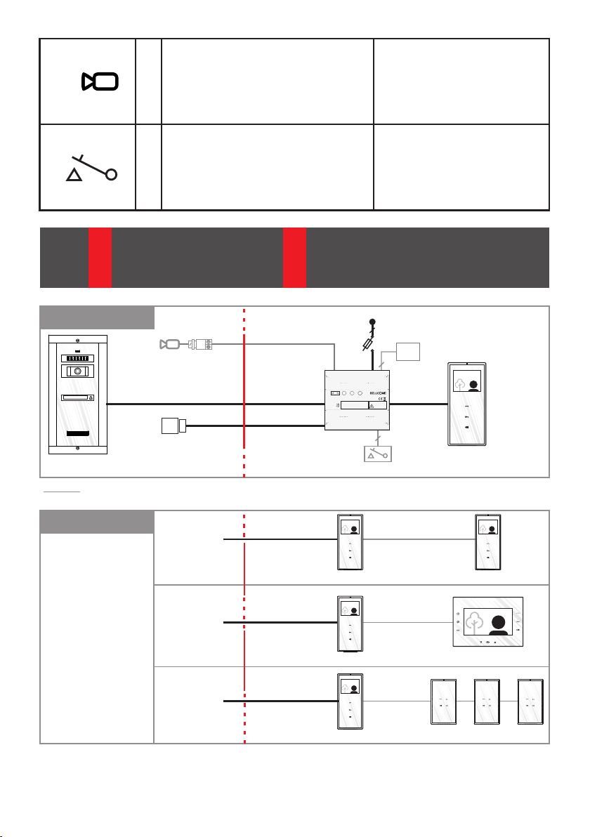
Video Inneneinheit
Video terminal
Poste intérieur vidéo
Terminale video
Video-terminal
Terminal wideo
VTT
1 x
212 x 96 x 22 mm
0,4 kg
o o
0 C … + 45 C
12 … 14 Vd.c.
v
Gehäuse
Case
Carcasse
Scatola
Huisvesting
Obudowa
LCD Display
LCD display
Écran LCD
Schermo LCD
LCD scherm
Ekran LCD
3
ABS + chemisch gehärtetes Glas – 3 mm
ABS + Chemically toughened glass - 3 mm
ABS + Verre trempé chimiquement - 3 mm
ABS + Vetro temperato chimicamente - 3 mm
ABS + Chemisch gehard veiligheidsglas - 3 mm
ABS + Chemicznie wzmocnione szkło - 3 mm
3.5” LCD, TFT
320 x RGB x 240
/ / / - 60/ 60/ 40 / 60
Zusatzprodukte (seperat zu erwerben)
Additional products (separately purchased)
Produits supplémentaires (vendus séparément)
Gleichstrom (DC) oder Wechselstrom (AC) Schloss
Direct current (DC) or Alternative current (AC) lock
Serrure électrique à courant continu (CC) ou alternatif (CA)
LCK
1 x
1 x
BAT
12V/7Ah
Serratura per corrente continuo (d.c.) o alternata (a.c.)
Gelijkstroom (DC) of wisselstroom (AC) slot
Prąd stały (DC) lub prąd zmienny (AC) blokada
Wiederaufladbare Batterie
Rechargeable battery
Accumulateur
BAT
Batteria ricaricabile
Oplaadbare batterij
Bateria do ponownego naładowania
Prodotti adizionali (acquisiti separatamente)
Aanvullende producten (apart verkrijgbaar)
Dodatkowe produkty (do kupienia oddzielnie)
12Vd.c., 1 Ad.c.
max. 24Va.c., 1 Aa.c.
12V / 7Ah
1 x
1 x
3 x
Standard Videoinneneinheit parallel betrieben
Standard video terminal in parallel
Poste intérieur vidéo Standard en parallèle
VTT
Terminale video Standard in parallelo
Standard parallelle video-terminal
Terminal wideo Standard równolegle
Advanced Videoinneneinheit parallel betrieben
Advanced video terminal in parallel
Poste intérieur vidéo Advanced en parallèle
VTA
Terminale video Advanced in parallelo
Advanced parallelle video-terminal
Terminal wideo Advanced równolegle
Bis zu 3 Advanced Audio Inneneinheiten parallel betrieben
Up to 3 Advanced audio terminals in parallel
Jusqu'à 3 postes intérieurs audio Advanced en parallèle
ATA
Fino a 3 terminali audio Advanced in parallelo
Tot 3 Advanced parallelle audio-terminals
Do 3 terminali audio Advanced równolegle
Passiver Videobalun
Passive video balun
Balun vidéo
PVB
Video balun
Video transformator
Pasywny balun video
3,5” LCD
320 x (RGB) x 240
/ / / - 60/ 60/ 40 / 60
212 x 96 x 22 mm
7“ LCD, TFT
800 x 3 (RGB) x 480
/ / / - 60/ 60/ 40 / 60
162 x 227 x 20 mm
170 x 96 x 22 mm
Für zusätzliche Videokameras
For additional video cameras
Pour des caméras vidéo supplémentaires
Per camere video adizionali
Voor extra videocamera's
Dla dodatkowych kamer wideo
4
1 x
1 Videokamera direkt an der SCU angeschlossen
1 video camera connected directly in SCU
1 caméra vidéo connectée directement à SCU
Vcam
1 camera video connessa direttamente con la SCU
1 Videocamera direct aangesloten in SCU
1 kamera wideo podłączona bezpośrednio w SCU
Türöffnungsschalter
Open door switch
Touche pour l'ouverture de la porte
SWC
Bottone apertura porta
Schakelaar deur openen
Przycisk otwierania drzwi
1 x PVB
+
Nicht selbsthaltend
Non-Latching
Sans blocage
Senza bloccaggio
Zonder vergrendeling
Bez zablokowania
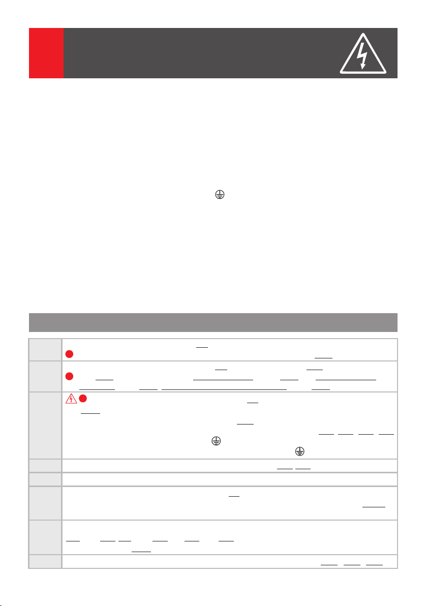
BLOCKDIAGRAMME
DE
BLOCK DIAGRAMS
EN
3
SCHÉMAS-BLOC
FR
DIAGRAMMA BLOCCO
IT
BLOKSCHEMA'S
NL
SCHEMAT BLOKOWY
PL
3.1.
UTP cat5e
Vcam
PVB
Name 1
LCK
VPT
““
optional optional en option opzionale optioneel opcjonalnie
3.2.
SCU (3.1.1) /
Zusätzliche Inneneinheiten
Additional terminals
Postes intérieurs
supplémentaires
Terminali adizionali
Extra terminals
Dodatkowe terminale
SCU (3.1.1) /
SCU (3.1.1) /
(AWG 24)
UTP cat5e
(AWG 24)
UTP cat5e
(AWG 24)
UTP cat5e
(AWG 24)
UTP cat5e
(AWG 24)
230 Va.c., 50 Hz
2 x 6Aa.c.
PROG
S1 S2 S3
STROMVERSORGUNGSEINHEIT (SCU.VDR02.BLW)
SCHLOSS-
ACHTUNG! Lebensgefahr,
EINGANG: 230V Wechselspannung 50Hz, 0.4A
3
2
ÖFFNUNGS-
4
1
Gerät nicht öffnen!
ZEIT
AUSGANG 1: 14V, 2A Gleichspannung (S1)
5
(sekunden)
AUSGANG 2: 14V, 0.5A Gleichspannung (S2)
6
GEFAHR EINES
10
7
BATTERIESTATUS: S3
STROMSCHLAGS!
9
8
SCU
SWC
VTT
VTT
3 x 0.75 mm
12V 7Ah
2 x 0.75 mm
UTP cat5e
2 x 0.75 mm
UTP cat5e
(AWG 24)
UTP cat5e
(AWG 24)
2
/
2
(AWG 24)
2
UTP cat5e
(AWG 24)
BAT
VTT
VTT2
VTA2
VTT
ATA2 ATA3 ATA4
5
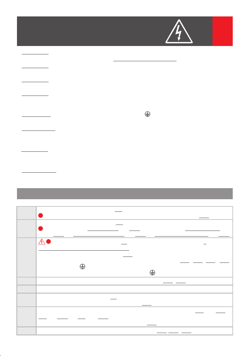
SICHERHEITSHINWEISE
DE
4
1. ACHTUNG! Die Installation, die Wartung und die Verbindung zum 230V / 50Hz Netz von der
Stromversorgungseinheit (SCU) darf nur von autorisiertem Personal durchgeführt werden!
2. ACHTUNG! Es ist ZWINGEND erforderlich, ein 3 x 0,75 mm Kabel und 2 automatische Sicherungen
(6A) zur Energieversorgung der Stromversorgungseinheit ("SCU") 230V / 50Hz Netz zu nutzen.
3. ACHTUNG! Während der Installation, Wartung und dem Anschluss der Stromversorgungseinheit
(SCU) an das 230V / 50Hz Netz, müssen die Sicherungen aus dem Schaltschrank geöffnet werden
.(POWER OFF)
4. ACHTUNG! LÖSEN SIE NICHT DIE FRONTKLAPPE DER STROMVERSORGUNGSEINHEIT (SCU)
STROMSCHLAGGEFAHR! Nur Schtzdeckel 1 und 2 dürfen während der Installation oder
Wartung geöffnet werden.
5. WICHTIG! Sie müssen die Anschlüsse für F, N und zu machen und den Schutzdeckel 1 und 2 von
der Zentraleinheit (SCU) montieren, und erst nach diesem Schritt können Sie die 2
Versorgungssicherungen (230V / 50Hz) verbinden.
6. Berühren Sie NICHT die Metallteile der Drähte oder die Klemmen der Anschlüsse von der
Stromversorgungseinheit (SCU) oder der Sicherungen. Sie müssen die 6 A Sicherungen (POWER OFF)
von der Versorgung trennen, und nur dann können Sie mit der Stromversorgungseinheit (SCU) arbeiten.
7. ACHTUNG! Versorgen Sie die Komponenten der Anlage (Außeneinheit, Inneineinheit, etc.) NIEMALS mit
einer Spannung höher als 14 V Gleichstrom oder mit (230V/50Hz) direkter Wechselspannung.
STROMSCHLAGGEFAHR und System Zerstörung.
8. ACHTEN SIE auf die richtige Polarität der Leiter während des Anschlusses eines Akkus (max. 7Ah/12 V
Gleichstrom) an die Stromversorgungseinheit (SCU)
während der Installation
4.1. Installationsschritte
Schritt 1
Schritt 2
Schritt 3
Schritt 4
Schritt 5
Schritt 6
Schritt 7
Schritt 8
Einbau der Außeneinheit (VPT) - Kap. 5.2.
!
Die elektrischen Anschlüsse müssen mit dem Schaltplan aus Kapitel 5.2.6. übereinstimmen
Einbau der Video Inneneinheit (VTT) – Kap.5.3. Für Verbindungen mit RJ45-Anschluss
- Kap. 5.3.2. Für Verbindungen mit Schraubklemmen – Kap.. 5.3.3. Für zusätzliche Video
!
Inneinheit – Kap. 5.3.4. Für zusätliche Audio Inneneinheiten – Kap. 5.3.5.
!
Einbau der Stromversogungseinheit (SCU) – Kap. 5.4. Autorisiertes Personal erforderlich!
– Kap.4. Mit den 6A automatischen Sicherungen in der OFF Position:
a. Platzieren Sie die SCU im Sicherungskasten – Kap. 5.4.1.
b. Machen Sie in der SCU die Verbindungen für VPT, VTT, (LCK, Vcam, etc.)-Kap. 5.4.2./5.4.3. (5.4.4., 5.4.5.)
c. Machen Sie die Verbindungen für F, N und in der SCU.
d. Machen Sie die Verbindungen an den automischen Sicherungen und zu Masse.
Überprüfen Sie die Richtigkeit aller Anschlüsse in der SCU – Kap.5.4.2/5.4.3.
Schalten Sie die automatischen Sicherungen 6A ein.
Überprüfen Sie die LED-Farben der SCU – Kap. 6.3. Im Falle einer rot blinkenden LED, schalten
Sie die automatischen Sicherungen 6A aus und beachten sie die FEHLERDIAGNOSE – Kap. 7
um die Ursache zu finden.
Mit einem Voltmeter, an den Gleichstrom angesetzt, überprüfen Sie die Spannungen an den Klemmen
SCU - Kap. 5.5.1, VPT -. Kap. 5.5.2. und VTT - Kap. 5.5.3. Wenn die Werte nicht übereinstimmen, siehe
FEHLERDIAGNOSE - Kap. 7 um die Ursache zu finden.
Überprüfen Sie die korrekte Funktion und Einstellungsänderungen – Kap. 6.4.1., 6.5.1., 6.5.2.
6
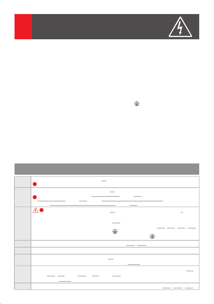
SAFETY INSTRUCTIONS
4
1. ATTENTION! The installation, the maintenance and the connection to the 230V/50Hz network
of the central unit (SCU) will be carried out only by authorized personnel!
2. ATTENTION! It is MANDATORY to use a 3 x 0,75 mm cable and 2 automatic fuses (6A) for
power supplying the central unit (SCU) from the 230V/50Hz network.
3. ATTENTION! During installation, connection of the central unit (SCU) to 230V/50Hz and
service, the safety fuses from the electric panel must be opened ( ).POWER OFF
4. ATTENTION! DO NOT UNFASTEN THE FRONT LID OF THE CENTRAL UNIT (SCU)! DANGER OF
ELECTRIC SHOCK! Only 1 and 2 protection lids of the connections can be unfastened during
installation or service.
5. IMPORTANT! You must make the connections for F, N and and mount the 1 and 2 protection
lids of the central unit (SCU) and only after these you can connect the 2 supply fuses (230V/50Hz)
6. DO NOT TOUCH the metallic parts of the wires or the terminals of the connectors from the
central unit (SCU) or from the fuses. You have to disconnect first the 6 A fuses ( ) fromPOWER OFF
the supply's phase and only then you can work with the central unit (SCU).
7. ATTENTION! Do not supply components of the installation separately (outdoor panel, terminals etc.)
at voltages higher than 14Vd.c. or directly from the network (230V/50Hz). DANGER OF ELECTRIC
SHOCK and system destruction.
8. PAY ATTENTION to the polarity of the terminals of the rechargeable battery (max. 7 Ah/ 12 Vd.c.)
when connecting it to the central unit (SCU).
during installation
2
EN
4.1. Installation steps
Step 1
Step 2
Step 3
Step 4
Step 5
Step 6
Step 7
Step 8
Install the Outdoor Panel (VPT) – Ch. 5.2.
!
The electrical connections must be in accordance with the diagram from Ch. 5.2.6.
Install the Video Terminal (VTT) – Ch. 5.3.
For connections with RJ45 connector - Ch. 5.3.2. For connections with screw connectors
!
- Ch. 5.3.3. For additional video terminal - Ch. 5.3.4. For additional audio terminals - Ch 5.3.5.
!
Install the Central Unit (SCU) – Ch. 5.4. Authorized personnel required! – Ch. 4
With the 6A automatic fuses in OFF position:
a. Place the SCU in the electric panel – Ch. 5.4.1.
b. Make in the SCU the connections for VPT, VTT (LCK, Vcam, e.t.c.) – Ch. 5.4.2./ 5.4.3. (5.4.4. , 5.4.5.)
c. Make the F, N and connections in SCU.
d. Make the F, N connections at the automatic fuses and to the ground.
Check the precision of all the connections made in SCU – Ch. 5.4.2/ 5.4.3.
Turn ON the 6A automatic fuses.
Check the LEDs colors of SCU – Ch. 6.3. In case of red signaling of any LED, turn OFF the
6A automatic fuses and see TROUBLESHOOTING – Ch. 7 to identify the cause.
With a voltmeter set on direct current, check the voltages on the terminals of SCU – Ch. 5.5.1.,
VPT - Ch. 5.5.2. and VTT – Ch. 5.5.3.
If the values do not match, see TROUBLESHOOTING – Ch. 7 and identify the cause.
Check the correct functioning and settings changing – Ch. 6.4.1, 6.5.1., 6.5.2.
7
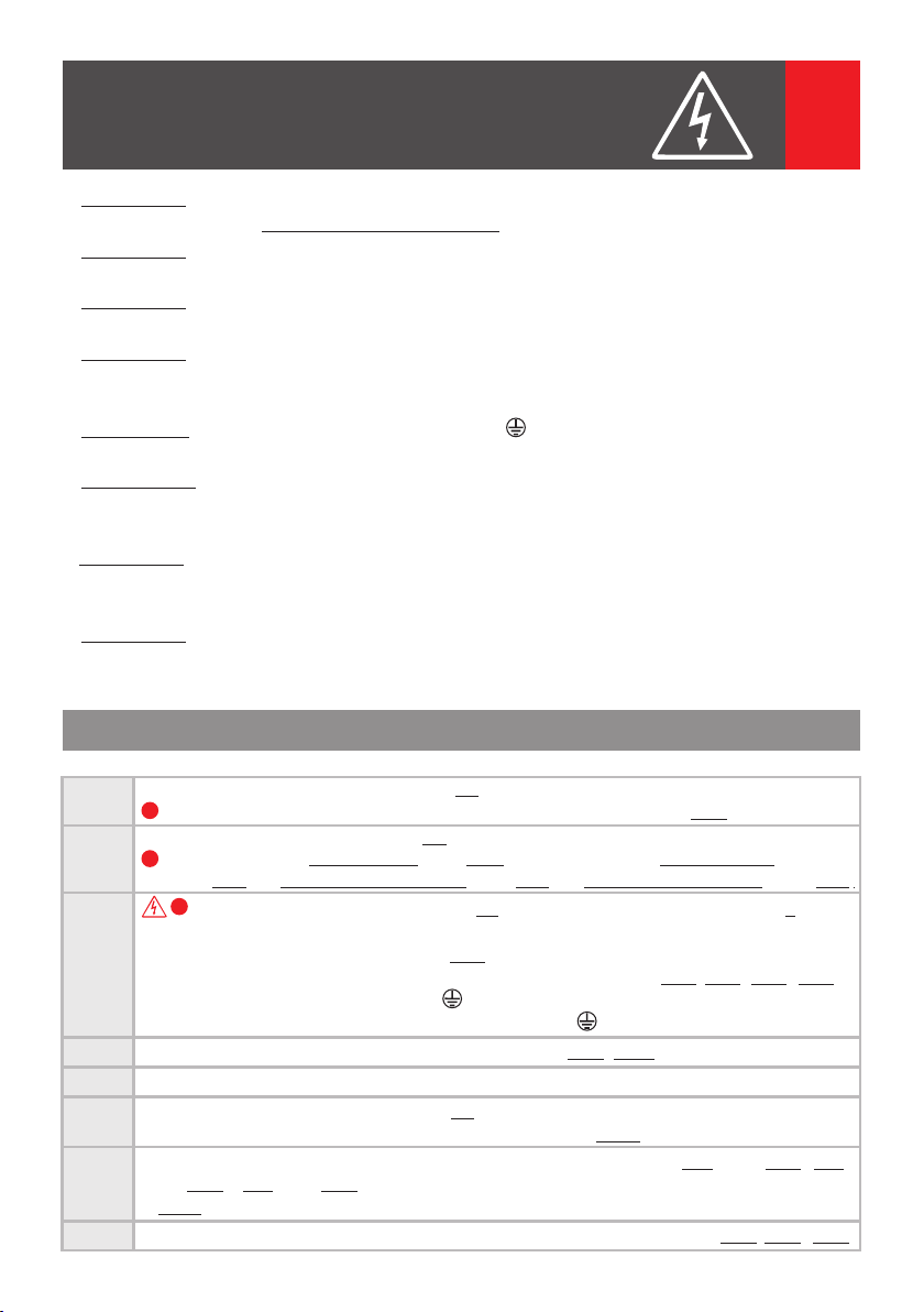
CONSIGNES DE SÉCURITÉ
FR
4
1. ATTENTION! L'installation, l'entretien et le branchement de l'unité centrale (SCU) au réseau de
230V/50Hz seront faites uniquement par du personnel autorisé!
2. ATTENTION! Il est obligatoire d'utiliser un câble de 3 x 0,75 mm2 et 2 fusibles automatiques (6A)
pour alimenter l'unité centrale (SCU) du réseau de 230 V/50 Hz.
3. ATTENTION! Lors de l'installation, du branchement de l'unité centrale (SCU) au réseau de
230 V/50 Hz et du service, les fusibles de protection du tableau électrique doivent être débranchés.
.(ALLIMENTATION ÉTEINTE)
4. ATTENTION! NE PAS DÉMONTER LE COUVERCLE FRONTAL DE L'UNITÉ CENTRALE (SCU) !
DANGER DE CHOC ÉLECTRIQUE! Seuls les couvercles de protection des connexions 1 et 2 peuvent
être démontés lors de l'installation ou du service.
5. IMPORTANT! Il faut d'abord réaliser les connexions pour F, N et et monter les couvercles de
protection 1 et 2 avant de brancher les 2 fusibles automatiques (230 V / 50 Hz).
6. NE PAS TOUCHER la partie métallique des fils ou les bornes de connexion de l'unité centrale (SCU)
ou des fusibles. Il faut d'abord débrancher les fusibles de 6A de la phase(ALLIMENTATION ÉTEINTE)
de l'alimentation avant de travailler sur l'unité centrale (SCU).
7. ATTENTION! Ne pas alimenter séparément les composants du système (platine de rue, postes
intérieurs etc.) à des tensions au-dessus de 14 V CC ou directement au réseau (230 V / 50 Hz).
DANGER DE CHOC ÉLECTRIQUE et de destruction du dispositif.
8. ATTENTION à la polarité des bornes de l'accumulateur (max. 7 Ah / 12 V CC) au moment de son
branchement à l'unité centrale (SCU).
pendant l'installation
4.1. Étapes de l'installation
Étape 1
Étape 2
Étape 3
Étape 4
Étape 5
Étape 6
Étape 7
Étape 8
Installer la platine de rue (VPT) - Chap. 5.2.
!
Les connexions électriques doivent être en concordance avec le schéma-bloc au Chap. 5.2.6.
Installer le poste intérieur vidéo (VTT) – Chap. 5.3.
Pour des connexions à l'aide des connecteurs RJ45 – Chap. 5.3.2. Pour des connexions à l'aide des
!
connecteurs à vis – Chap. 5.3.3. Pour le poste intérieur vidéo supplémentaire – Chap. 5.3.4.
Pour le postes intérieurs audio supplémentaires – Chap. 5.3.5.
!
Installer l'unité centrale (SCU) – Chap. 5.4. Personnel autorisé seulement! – Chap. 4
Avec les fusibles automatiques de 6A débranchés :
a. Placer SCU dans le tableau électrique – Chap. 5.4.1.
b. Réaliser dans SCU les connexions pour VPT, VTT (LCK, Vcam, etc.) – Chap. 5.4.2./5.4.3. (5.4.4., 5.4.5.).
c. Réaliser dans SCU les connexions pour F, N et .
d. Réaliser les connexions de F et N aux fusibles automatiques et de la à la terre.
4
Vérifier l'exactitude des connexions dans SCU – Chap. 5.4.2./5.4.3.
Brancher les fusibles automatiques de 6A.
Vérifier la couleur des LED sur SCU – Chap. 6.3. Au cas où une des LED est rouge, débrancher
les fusibles automatiques de 6A et voir DÉPANNAGE – Chap. 7 pour en identifier la cause.
À l'aide d'un voltmètre positionné sur courant continu, vérifier les tensions aux bornes de SCU
– Chap. 5.5.1., VPT - Chap. 5.5.2. et VTT– Chap. 5.5.3. Si les valeurs ne correspondent pas, voir
DÉPANNAGE – Chap. 7 pour en identifier la cause.
Vérifier l'exactitude du fonctionnement et du réglage des fonctions - Chap. 6.4.1., 6.5.1., 6.5.2.
8
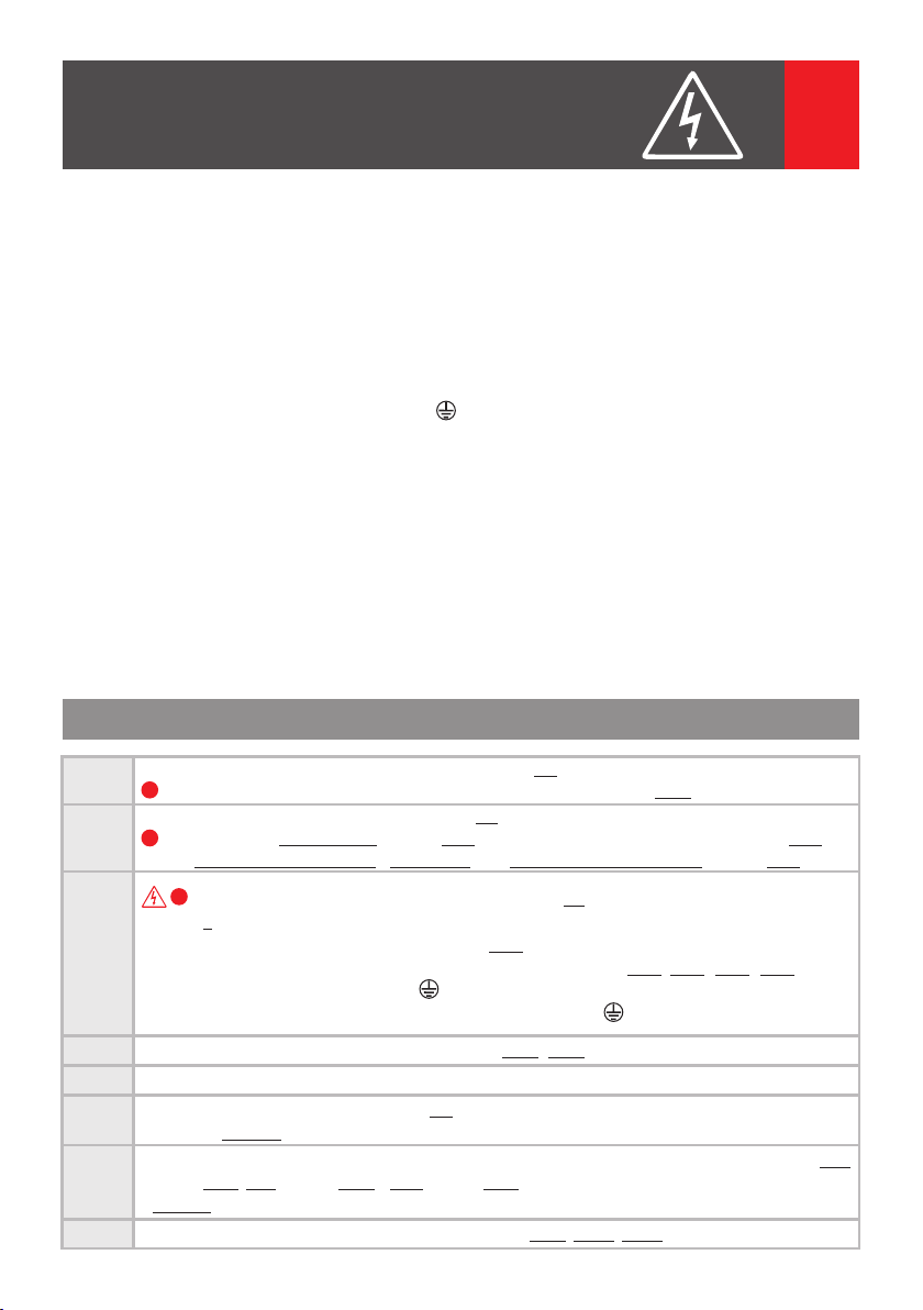
ISTRUZIONI DI SICUREZZA
4
1. ATTENZIONE! Il montaggio, la manutenzione e la connessione dell'unità centrale (SCU) alla rete di
230V/50 Hz va eseguita soltanto da persone autorizzate!
2. ATTENZIONE! È imperativo l'uso di un cavo di 3 x0.75 e di 2 dispositivi di sicurezza (fusibili)
automatici (6A) per l'alimentazione dell'unità centrale (SCU) dalla rete di 230V/50 Hz.
3. ATTENZIONE! Durante l'installazione, la connessione dell'unità centrale (SCU) a 230V/50Hz e dello
service, i fusibili per la protezzione dello quadro elettrico devono essere staccati ( ).FORNIMENTO FERMO
4. ATTENZIONE! NON TOGLIETE IL COPERCHIO CENTRALE FRONTALE DELL'UNITÀ CENTRALE (SCU)!
PERICOLO DI SCOSSA ELETTRICA! Solo i coperchi di protezione 1 e 2 delle connessioni possono
essere tolte durante l'installazione oppure durante le riparazioni.
5. IMPORTANTE! Servono effettuate le connessioni F, N e e installati i coperchi di protezione 1 e 2
dopo di che possonno essere inseriti i 2 fusibili automatici per la sicurezza(230V/50Hz).
6. NON TOCCATE! IL lato metallico dei fili o i morsetti di connessione dell'unità centrale (SCU) o dei
fusibili. Prima dovete fare la sconnessione dai fusibili di 6A ( ) dall'alimentazione eFORNIMENTO CESSATA
poi potete lavorare con l'unità centrale (SCU).
7. ATTENZIONE! Non fornite in modo separato componenti dell'impianto (pannello esterno, terminale, ecc.)
a tensione superiore a 14 V c.c. o direttamente alla rete (230V/50Hz). PERICOLO DI SCOSSA ELETTRICA
E DI DISTRUZIONE DELL'INSTALLAZIONE.
8. ATTENZIONE! La polarità dei morsetti della batteria(massimo 7 Ah/ 12 Vc.c.) al momento della sua
connessione all'unità centrale (SCU).
durante il montaggio
IT
4.1. Le tappe dell'installazione
Passo 1
Passo 2
Passo 3
Passo 4
Passo 5
Passo 6
Passo 7
Passo 8
Installate il pannello esterno (VPT) - Cap. 5.2.
!
Le connessioni elettriche devono corrispondere con la scheda del Cap. 5.2.6.
Installate il terminale video(VTT)– Cap. 5.3.
Per connessioni con connettori RJ45 – Cap. 5.3.2. Per connnessioni con connettori a vite
!
– Cap. 5.3.3. Per terminale video adizionale – Cap. 5.3.4. Per terminali audio adizionali – Cap. 5.3.5.
!
Installate l'unità centrale(SCU) – Cap. 5.4. Solo da personale autorizzato! – Cap. 4
Con fusibili automatici di 6A sconnessi:
a. Mettere SCU nel quadro elettrico – Cap. 5.4.1.
b. Eseguite nel SCU le connessioni per VPT, VTT (LCK, Vcam, ecc.) – Cap. 5.4.2./5.4.3. (5.4.4., 5.4.5.)
c. Eseguite SCU le connessioni per F, N e .
d. Eseguite le connessioni F, N presso i fusibili automatici e a terra.
Verificate la correttezza delle connessioni nel SCU– Cap. 5.4.2./5.4.3.
Fatte la connessione dei fusibili automatici da 6A.
Verificate il colore dei LED su SCU – Cap. 6.3. In caso in cui uno dei LED-è rosso, dovete fare la
sconnessione dai fusibili di 6A e verificate le RIPARAZIONI – Cap. 7 per trovare la causa.
Verificate con uno voltometro a corrente continuo le tensioni ai morsetti SCU – Cap. 5.5.1., VPT
- Cap. 5.5.2. e VTT– Cap. 5.5.3. Se i valori non corrispondono verificate la RIPARAZIONE
– Cap. 7 e identificate la causa.
Verificate la correttezza del funzionamento e del cambio delle opzioni - Cap. 6.4.1, 6.5.1., 6.5.2.
9

VEILIGHEIDSINSTRUCTIES
NL
4
1. LET OP! Het installeren, onderhoud en aansluiten van de centrale eenheid (SCU) op het 230V/50Hz
netwerk mag alleen worden gedaan door bevoegd personeel!
2. LET OP! Het is verplicht om een k abel van 3 x 0,75 mm en 2 automatische zekeringen (6A) te
gebruiken voor de stroomtoevoer van de centrale eenheid (SCU) van het 230V/50Hz netwerk.
3. LET OP! Tijdens het installeren, het aansluiten van de centrale eenheid (SCU") op 230V/50Hz en
het onderhoud, dienen de veiligheidszekeringen van het elektrische schakelbord losgekoppeld te
worden ( ).STROOM UIT
4. LET OP! HET VOORPANEEL VAN DE CENTRALE EENHEID (SCU) NIET LOSMAKEN! RISICO OP
ELEKTRISCHE SCHOK! Alleen veiligheidsklepjes 1 en 2 van de aansluitingen kunnen losgemaakt
worden tijdens het installeren of het onderhoud.
5. BELANGRIJK! De aansluitingen voor F, N en dienen gemaakt te worden en de veiligheidsklepjes
1 en 2 gemonteerd te worden en pas daarna kunnen de 2 automatische zekeringen aangesloten
worden (230V/50Hz).
6. De metalen delen van de draden of aansluitklemmen van de centrale eenheid (SCU) of van de
zekeringen NIET AANRAKEN!. U dient eerst de 6A zekeringen los te koppelen ( ) van deSTROOM UIT
voedingsfase en pas daarna kunt u met de centrale eenheid (SCU) aan de slag.
7. LET OP! De onderdelen van de installatie (buitenpaneel, terminals, etc.) niet separaat voorzien van
spanningen boven 14 V D.C. of rechtstreeks op het netwerk (230 V/50 Hz) aansluiten.
RISICO VAN ELEKTRISCHE SCHOK en beschadiging van de installatie.
8. LET OP de polariteit van de aansluitklemmen van de accu (max. 7 Ah/ 12 V D.C.) bij aansluiting op
de centrale eenheid (SCU).
tijdens de installatie
4.1. Installatiestappen
Stap 1
Stap 2
Stap 3
Stap 4
Stap 5
Stap 6
Stap 7
Stap 8
Het buitenpaneel (VPT) installeren – Hfdst. 5.2.
!
De elektrische aansluitingen dienen in overeenstemming te zijn met het schema van Hfdst. 5.2.6.
De video-terminal (VTT) installeren - Hfdst. 5.3.
Voor aansluitingen met RJ45-connectoren - Hfdst. 5.32. Voor aansluitingen met schroef connectoren
!
- Hfdst. 5.3.3. Voor extra video-terminal - Hfdst. 5.3.4. Voor extra audio-terminals - Hfdst. 5.3.5.
!
De centrale eenheid (SCU) installeren - Hfdst. 5.4. Alleen bevoegd personeel! - Hfdst. 4
Met de automatische 6A zekeringen losgekoppeld:
a. Plaats de SCU in het elektrische schakelbord - Hfdst. 5.4.1.
b. Maak in de SCU de aansluitingen voor VPT, VTT (LCK, Vcam, enzv.) - Hfdst. 5.4.2. /5.4.3. (5.4.4., 5.4.5.)
c. Maak de aansluitingen voor F, N en in SCU.
d. Maak de F, N aansluitingen bij de automatische zekeringen en bij de aarde.
Controleer de deugdzaamheid van de aansluitingen in SCU - Hfdst. 5.4.2. / 5.4.3.
De 6A automatische zekeringen aansluiten.
Controleer de kleur van de LEDs op SCU - Hfdst. 6.3. Indien een van de LEDs rood is, uitschakel de 6A
automatische zekeringen en controleer PROBLEMEN VERHELPEN - Hfdst. 7 en identificeer de oorzaak.
Met een voltmeter ingesteld op gelijkstroom (DC), controleer de spanningen op de terminals van
SCU - Hfdst . 5.5.1, VPT - Hfdst. 5.5.2. en VTT - Hfdst. 5.5.3. Indien de waarden niet
overeenkomen, controleer PROBLEMEN VERHELPEN - Hfdst. 7 en identificeer de oorzaak.
Controleer de correcte werking en het wijzigingen van instellingen - Hfdst. 6.4.1, 6.5.1., 6.5.2.
10
ZASADY BEZPIECZEŃSTWA
4
1. UWAGA! Instalacja, utrzymanie i podłączenie do sieci 230V / 50Hz jednostki centralnej (SCU) będą
wykonywane wyłącznie przez autoryzowany personel!
2. UWAGA! Jest to obowiązkowe, aby użyć kabla 3 x 0,75 mm i 2 automatyczne bezpieczniki (6A) do
zasilania jednostki centralnej (SCU) z sieci 230V / 50Hz.
3. UWAGA! Podczas instalacji, podłączenia jednostki centralnej (SCU) do 230V / 50Hz i serwisu,
bezpieczniki zabezpieczające z panelu elektrycznego muszą być odłaczone ( ).WYŁACZONE ZASILANIE
4. UWAGA! NIE ZDEJMOWAĆ PRZEDNIĄ POKRYWĘ JEDNOSTKI CENTRALNEJ (SCU)! RYZYKO PORAŻENIA
PRĄDEM! Tylko pokrywy ochronne 1 i 2 z połączeń moga być rozpięte/zdjete podczas instalacji lub usługi.
5. WAŻNE! Należy wykonać podłączenia dla F, N i i zamontować pokrywy ochronne 1 i 2 jednostki
centralnej (SCU) i dopiero po nich można podłączyć 2 bezpieczniki zasilania automatyczne (230V / 50Hz).
6. NIE DOTYKAĆ metalowych części przewodów lub końcówek złączy od jednostki centralnej (SCU) lub
z bezpiecznikami. Musisz najpierw odłączyć bezpieczniki A 6 (WYŁAZCENIE ZASILANIA) z fazy zasilania
i dopiero wtedy można pracować z jednostką centralną (SCU).
7. UWAGA! Nie zasilać oddzielnie komponenty instalacji (panel zewnetrzny, terminale itp) przy napięciach
wyższych niż 14 Vd.c. lub bezpośrednio z sieci (230V / 50Hz). NIEBEZPIECZENIE PORAŻENIA PRĄDEM
ELEKTRYCZNYM i zniszczenie systemu.
8. UWAGA! Należy zwrócić uwagę na polaryzację zacisków akumulatora (maks. 7 Ah / 12 Vd.c.) podczas
podłączania go do jednostki centralnej (SCU).
podczas instalacji
PL
4.1. Kroki instalacji
Krok 1
Krok 2
Krok 3
Krok 4
Krok 5
Krok 6
Krok 7
Krok 8
Zainstalowanie panelu zewnetrznego (VPT) - Rozdz. 5.2.
!
Połączenia elektryczne muszą być zgodne ze schematem z Rozdz. 5.2.6.
Zainstalowanie terminala wideo (VTT) – Rozdz. 5.3.
Dla połączeń ze złączami RJ45 – Rozdz. 5.3.2. Dla połączeń ze złączami ze śrubą – Rozdz. 5.3.3.
!
Dla dodatkowy terminal video– Rozdz. 5.3.4. Dla dodatkowe terminale audio – Rozdz. 5.3.5.
!
Zainstalowanie jednostki centralnej (SCU) – Rozdz. 5.4. Wymagane autoryzowany personel!
– Rozdz 4. Z automatycznymi bezpiecznikami 6A odłączonymi:
a. Umieścić SCU w panelu elektrycznym – Rozdz. 5.4.1.
b. Dokonać w SCU połączenia dla VPT, VTT (LCK, Vcam, itp.) – Rozdz. 5.4.2./5.4.3. (5.4.4., 5.4.5.)
c. Dokonać w SCU połączenia dla F, N i .
d. Wykonać podłączenia F, N do automatycznych bezpieczników i do ziemi.
Sprawdzić prawidłowość połaczeń SCU – Rosdz. 5.4.2./5.4.3
Podłączyć bezpieczniki automatyczne 6A.
Sprawdż kolor diody LED SCU- Rozdz. 6.3. Jeśli jedna z diod LED jest czerwona, nalezy
sprawdzic Rozdz. 7 - ROZWIĄZYWANIE PROBLEMÓW i zidentyfikować przyczynę.
Za pomoca Woltomierza ustawionego na prąd stały, należy sprawdzić napięcie na zaciskach SCU
- Rozdz. 5.5.1, VPT - Rozdz. 5.5.2. i VTT - Rozdz. 5.5.3. Jeśli wartości nie są zgodne, zobacz
Rozdz. 7 - ROZWIĄZYWANIE PROBLEMÓW i zidentyfikowanie przyczyny.
Sprawdzić poprawne działanie i ustawienia - Rozdz. 6.4.1, 6.5.1., 6.5.2.
11

DE
EN
5
FR
5.1.
Erforderliches Kabel
Required cable
Le câble nécessaire
Il Cavo necessario
Vereiste kabel
Wymagany kabel
INSTALLATION
INSTALLATION
INSTALLATION
VPT SCU
SCU VTT
SCU LCK
SCU 230 Va.c./
50 Hz
SCU Vcam
≤ 30 m ≤ 50 m
UTP (FTP) cat. 5e
AWG24
UTP (FTP) cat. 5e
AWG24
2 (3) x 0.75 mm
3 x 0.75 mm
UTP (FTP) cat. 5e
AWG24
UTP (FTP) cat. 5e
UTP (FTP) cat. 5e
2
2
2 (3) x 0.75 mm
3 x 0.75 mm
UTP (FTP) cat. 5e
INSTALLAZIONE
IT
INSTALLATIE
NL
INSTALOWANIE
PL
AWG24
AWG24
2
2
AWG24
≤ 100 m
UTP (FTP) cat. 5e
AWG24 +
2
3x0.75 mm
UTP (FTP) cat. 5e
AWG24 +
2
3x0.75 mm
2
2 (3) x 1 mm
2
3 x 0.75 mm
UTP (FTP) cat. 5e
AWG24
≤ 150 m
UTP (FTP) cat. 5e
AWG24 +
3x0.75 mm
UTP (FTP) cat. 5e
AWG24 +
3x0.75 mm
2 (3) x 1 mm
-
-
Contact the producer
2
Contact the producer
2
2
150 m
≤
-
-
-
orange
1
orange / weiß
blau
2
blau / weiß
braun / weiß
3
braun
UTP cat 5e
(AWG24)
4
grün / weiß
grün
5.2. VPT
5.2.1
Einbau der Außeneinheit
Installation of the outdoor panel
Installation de la platine de rue
Installazione del pannello esterno
Installatie van het buitenpaneel
Instalacja Panelu zewnętrznego
5.2.2
Unterputz Version
Flush version
Version encastrée
Versione incasso
Inbouwversie
Wersja pochowana
orange
orange / white
blue
blue / white
brown / white
brown
green/ white
green
294x144x53 mm
5cm
orange
orange / blanc
blue
blue / blanc
marron / blanc
marron
vert/ blanc
vert
12
arancione
arancione / bianco
blu
blu / bianco
marrone / bianco
marrone
verde/ bianco
verde
260x110x33 mm
≈20cm
oranje
oranje / wit
blauw
blauw / wit
bruin / wit
bruin
groen/ wit
groen
150
cm
pomarańczowy
pomarańczowy / biały
niebieski
niebieski / biały
brązowy / biały
brązowy
zielony/ biały
zielony
o
70
170
cm
Torx 1
Torx 2
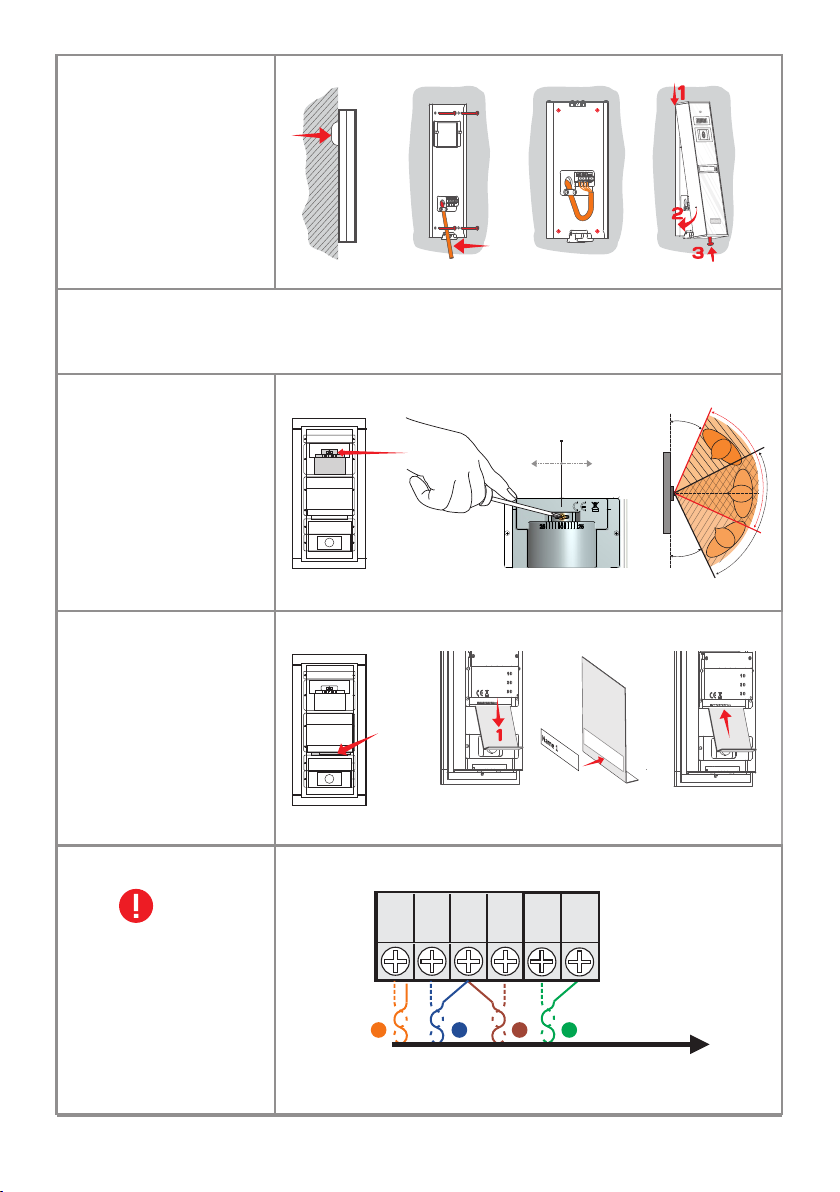
5.2.3
3
Aufputz Version
Surface version
Version en surface
Versione in superficie
Oppervlekversie
Wersja powierzchniowa
1.5
cm
≈20cm
Torx 2
Anti Diebstahl Schutz. Schrauben Sie die Torx 2 fest!
Antitheft protection. Screw the Torx 2 completely!
Protection antivol. Visser complètement Torx 2 !
5.2.4
Kamerapositionierung
Camera positioning
Positionnement de la caméra
La posizione della camera
De plaatsing van de camera
Ustawienie kamery
25 25
0
5.2.5
Einfügen der Namen
Name insertion
Insertion du porte-nom
Inserire il nome
Naam invoegen
Wstawienie nazwy
25 25
0
Protezione antifurto. Avitate completamente Torx 2!
Diefstalbeveiliging. Torx 2 volledig inschroeven!
Ochrona przed kradzieżą. Zakręcić całkowicie Torx 2!
o
o o o
+25 75 +25
75
o
25
o
25
o
75
2
5.2.6
Elektrische Verbindungen
Electrical connections
Connexions électriques
Connessioni elettriche
Elektrische aansluitingen
Połączenia elektryczne
VPT
V
CD
+14
1
GND
2
Vout
P
3
GNV
4
UTP cat5e
(AWG 24)
SCU
13
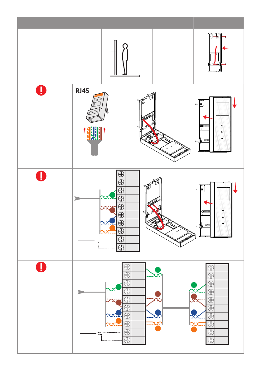
5.3. VTT
5.3.1
Einbau der Video Inneneinheit
Installation of the video terminal
Installation du poste intérieur vidéo
Installazione del Terminale video
Installeren van de video terminal
Instalacja terminala wideo
135 cm
170 cm
Aufputz
Surface
En surface
Su superficie
Oppervlak
Na powierzchni
≈20cm
UTP cat5e
(AWG 24)
5.3.2
Elektrische Verbindungen
mit RJ45
Electrical connections with
RJ45 connector
Connexions électriques à
l'aide du connecteur RJ45
Connessioni elettriche a
connettore RJ45
Elektrische aansluitingen
met RJ45 connector
Połączenie elektryczne ze
złączem RJ45
5.3.3
Elektrische Verbindungen mit
Schraubklemmen
Electrical connections with
screw connectors
Connexions électriques à
l'aide des connecteurs à vis
Connessioni elettriche a
connettori a vite
Elektrische aansluitingen met
schroef connector
Połączenia elektryczne ze
złączami śrubowymi
5.3.4
Zusätzliche Video Inneneinheit
Additional video terminal
Poste intérieur vidéo
supplémentaire
Terminale video adizionale
Extra video terminal
Dodatkowy terminal wideo
SCU (3.1.1)
SCU (3.1.1)
UTP cat5e
(AWG 24)
Türklingel
Doorbell
SCU (3.1.1)
UTP cat5e
(AWG 24)
Türklingel
Doorbell
UTP cat5e
(AWG 24)
4
3
2
1
VTT (3.5”)
4
3
2
1
t
u
o
NV
G
t
u
Vo
n
i
V
GN
Vin
V
U
+
ND
G
D
C
4V
1
+
BL2
D
1
BL
D
o
V
N
G
out
V
NV
G
Vi
+UV
GND
D
C
+1
DBL2
L
B
D
VTT 3.5”
14
2
1
2
1
ut
4
n
i
n
3
2
UTP cat5e
4
1
(AWG 24)
1
4
3
2
1
video
VTT 3,5” (VTA7”)
GNVo
V
GN
+
GND
+14
DBL2
D
V
CD
B
UV
t
u
t
u
o
n
Vi
n
i
1
L
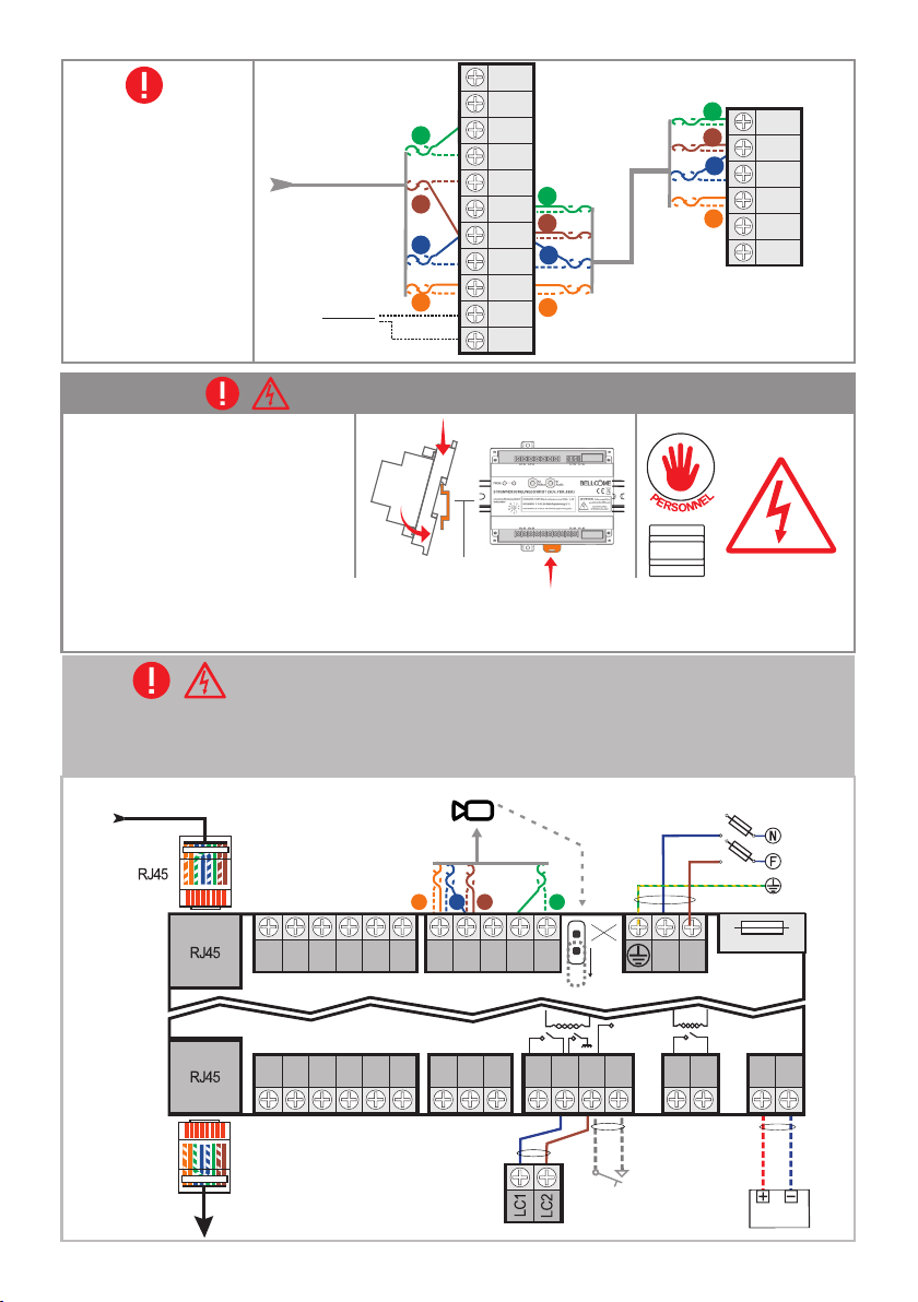
5.3.5
Zusätzliche Audio Inneneinheiten
Additional audio terminals
Postes intérieurs audio
supplémentaires
Terminale audio adizionale
Extra audio terminals
Dodatkowe terminale audio
SCU (3.1.1)
UTP cat5e
(AWG 24)
Türklingel
Doorbell
4
3
2
1
VTT 3.5”
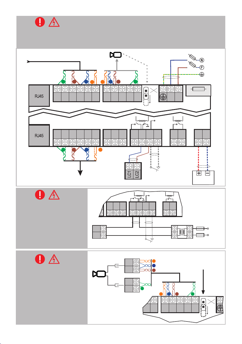
5.4. SCU
5.4.1
Einbau der Stromversorungseinheit
Installation of the central unit
Installation de l'unité centrale
Installazione dell'unità centrale
Installatie van de centrale eenheid
Instalacja jednostki centralnej
Sehen Sie Kap. 4 + 6.2 für Sicherheitsanweisungen und Beschreibung
See ch. 4 + 6.2 for safety instructions and description
Voir Chap. 4 + 6.2 pour des consignes de sécurité et description
5.4.2
Elektrische Verbindungen mit RJ45
Electrical connections with RJ45 connector
Connexions électriques à l'aide du connecteur RJ45
UTP cat5e (AWG 24)
VPT
P
Vin
GNV
GND
1
2
1
CD
+14
t
ou
NV
G
t
ou
DIN
V
n
NVi
G
in
V
V
U
+
4
D
GN
3
ND
G
2
DB
DB
CD
4
1
+
L2
L1
1
UTP cat5e
(AWG 24)
3
4
G
3
G
2
CD
+
1
1
B
D
D
audio ATA
R
O
I
H
Z
T
E
U
D
A
SCU
Verificate il cap. 4+6.2 per istruzioni di sicurezza e descrizione
Zie hfdst. 4 + 6.2 voor veiligheidsinstructies en beschrijving
Sprawdzić rozdz. 4 + 6.2 dla instrukcji bezpieczeństwa i opisu
Connessioni elettriche a connettore RJ45
Elektrische aansluitingen met RJ45 connector
Połączenie elektryczne ze złączem RJ45
Vcam
2 x
6
Aa
.c
N F
.
3 x
0,7
5 mm²
1.6A
JP
set
3
2
CD
+12
GND
Vcam
4
Vcam
Vin
Vin
Vcam
GNV
B
ND
ND
1
4
L2
1
L
2
3
0 V
a
.c.
5
0
H
z
VTT (3.1.1)
UTP cat5e
(AWG 24)
SC
U
Uv
CD
Vout
GNV
+14
GND
+14
GND
0.75 mm²
LCK
max. 1Ad.c.
LA
+Uv
2 x
+14V
-
LC
LA/C
SWC
max.
1Ad.c.
SWC
2 x
0.75 mm²
AUX1
AUX2
2 x
0.75 mm²
+
BAT
BAT
BA
TTE
R
Y
BAT
1
2V
m
a
x.7
Ah
15
+15
+14
+Uv
LA
LA/C
LC
SWC
AUX1
AUX2
GND
SC
U
+14V
CD
+14
+12
GND
CD
Vin
Vcam
Vcam
GNV
Vin
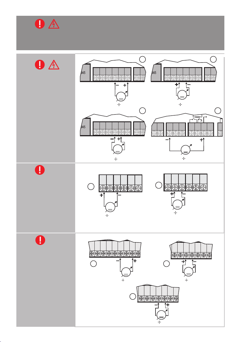
5.4.3
Elektrische Verbindungen mit Schraubklemmen
Electrical connections with screw connectors
Connexions électriques à l'aide des connecteurs à vis
Connessioni elettriche a connettori a vite
Elektrische aansluitingen met schroef connector
Połączenia elektryczne ze złączami śrubowymi
VPT
UTP cat5e
5.4.4
LCK (max. 1A)
Optionales Wechselstrom Schloss
Optional AC lock
Serrure à courant alternatif en option
Serratura di sicurezza C.A. opzionale
Optioneel AC slot
Blokada S.A. opcjonalna
5.4.5
Vcam (max. 0,4A)
Optionale Videokamera
Optional video camera
Caméra vidéo en option
Camera video opzionale
Optionele videocamera
Opcjonalna kamera wideo
(AWG 24)
Vcam
2
3
m
²
1.6A
+
BAT
B
A
T
1
2V
2x6,3 A
T
/7
ERY
5
Ah
0Hz
-
BAT
230Va.c.
0 Va.c.
2 x
0.75 mm²
BAT
50Hz
2 x
6Aa.
.
c
JP
set
4
GNV
GNV
4
3
P
Vin
Uv
Vout
3
VTT (3.1.1)
2
CD
GND
SC
CD
GND
2
UTP cat5e
(AWG 24)
U
3
2
1
1
Vin
+12
GND
+14
GND
2 x 0.75 mm²
LCK
max. 24 Va.c.
50Hz
CD
GNV
+Uv
max. 1Ad.c.
+14
+14
1
LCK
LCK
LCK
Vcam
4
Vin
LA
LA/C
max. 1Aa.c. (open door)
SWC
Vcam
Vcam
+14V
LC
SWC
0.75 mm²
SWC
max.
1Aa.c.
2 x 0.75 mm²2 x 0.75 mm²
max. 24 Va.c.
50Hz
2 x
N F
3 x
0,
75 m
AUX1
AUX2
RC
RC1
BNC
+12V
GND
Vin
GNV
PVB
16
V
ca
m
(Traf. balun)
1
2
3
4
21
S
CU
4
3
GNV
Vout
+Uv
GND
CD
+14
+14
GND
CD
+14
+14
+Uv
LA
LA/C
LC
SWC
AUX1
GND
+14V
5.5.
GNV
Vout
+Uv
GND
CD
+14
+14
GND
GNV
Vout
+Uv
GND
CD
+14
+14
GND
V
out
G
N
V
o
u
t
+
U
V
G
ND
C
D
+14
V
DB
L2
Vin
GN
V
i
n
Vo
ut
+U
V
G
N
D
C
D
+
14
V
DB
L
2
Vin
GNV
i
n
V
ou
t
+
U
V
G
N
D
C
D
+
14V
DB
L
2
V
in
G
N
V
i
n
Überprüfen der Spannung (SCU verbunden mit 230 Va.c.)
Checking the voltages (SCU connected to 230 Va.c.)
Vérification des tensions d'alimentation (SCU branchée à 230 V CA)
Verificate le tensioni di alimentazione (SCU connesso a 230 Va.c.)
Controle van toevoerspanningen (SCU aangesloten op 230 V a.c.)
Sprawdzanie napięcia zasilania (SCU podłączony do 230 Va.c.)
5.5.1
SCU
Überprüfen der Spannung
Checking the voltages
Vérification des tensions
d'alimentation
Verificate le tensioni
Controle van toevoerspanningen
Sprawdzanie napięcia zasilania
5.5.2
VPT
Überprüfen der Spannung
Checking the voltages
Vérification des tensions
d'alimentation
Verificate le tensioni
Controle van toevoerspanningen
Sprawdzanie napięcia zasilania
V
+14
1
12V 14.3Vd.c.
SCU
V
13,5 14,3Vd.c.
SCU
V
3.0 4.8Vd.c.
VPT
CD
GND
P
V
1
2
SCU
V
13,5 14,3Vd.c.
3
U
SC
4
V
13,5 14,3Vd.c.
VPT
V
CD
Vout
GNV
+14
2
Vout
GND
GNV
P
V
3.0 4.8Vd.c.
5.5.3
VTT
Überprüfen der Spannung
Checking the voltages
Vérification des tensions
d'alimentation
Verificate le tensioni
Controle van toevoerspanningen
VTT
1
2
V
12V 14.3Vd.c.
3
VTT
VTT
V
12V 14.3Vd.c.
Sprawdzanie napięcia zasilania
V
17
3.0 4.8Vd.c.
DE
6
BENUTZUNG DER VIDEOTÜRSPRECHANLAGE
6.1. SICHERHEITSHINWEISE während des Gebrauchs
è Schlagen Sie nicht mit harten Gegenständen auf die Produkte.
è Schützen Sie die Produkte vor Kalk und Staub während der Renovierung.
6.2. Bedeutung der akustischen Signale/Verwendung der Tasten
BEEP
[ ]
BEEP
2 x [ ]
BEEEEP
[ ]
[ ]
BEEEEP
Anruferton der
Inneinheit (VTT)
Anruferton der
Außeneinheit (VPT)
Zugangston bei der
Inneneinheit (VTT)
Zugangston bei der
Außeneinheit (VPT)
Türklingelton der
Inneneinheit (VTT)
Kurze Berührung einer
Taste
Langes Drücken von 1
oder 2 Tasten gleichzeitig
Kurzer Bestätigungston mit einem hohen Ton.
Zwei kurze Beep mit einem hohen Ton.
Langer Bestätigungston mit einem hohen Ton.
Langer Störungs Beep mit niedrigem Ton.
5 einstellbare Klingeltöne. Bei Ruf wird der eingestellte Klingelton
abgespielt.
Jeder Berührung von folgt ein ding-dong.
Wenn der Zugang gewährt wurde, ertönt an der Inneneinheit ein
Bestätigungston.
Wenn der Zugang gewährt wurde, ertönt an der Außeneinheit ein
Bestätigungston.
Bestimmter Türklingelton (wenn eine Türklingel an der Inneneinheit
angeschlossen ist).
Max. 1 Sek. wird bestätigt mit 1 x [ ].
Länger als 2 Sek. wird bestätigt mit 1 x [ ].
BEEP
BEEEEP
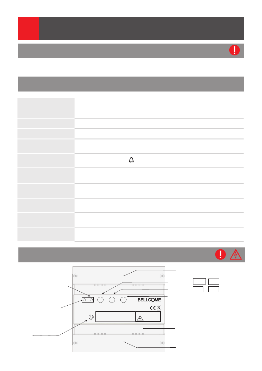
6.3. Eigenschaften der Stromversorgungseinheit (SCU)
Schutzdeckel 1 für elektrische
*Programmierungsknopf
PROG.
Rote LED of PROG
(Programmierungsmodus
oder Defekt innerhalb
der Anlage)
TIME:
Schloss Zeiteinstellung
PROG
STROMVERSORGUNGSEINHEIT (SCU.VDR02.BLW)
SCHLOSSÖFFNUNGSZEIT
(sekunden)
S1 S2 S3
EINGANG: 230V Wechselspannung 50Hz, 0.4A
3
2
4
1
AUSGANG 1: 14V, 2A Gleichspannung (S1)
5
AUSGANG 2: 14V, 0.5A Gleichspannung (S2)
6
10
7
BATTERIESTATUS: S3
9
8
ACHTUNG! Lebensgefahr,
Gerät nicht öffnen!
GEFAHR EINES
STROMSCHLAGS!
Anschlüsse
S1: GRÜN
S2: GRÜN
S3: GRÜN/ROT Batterie Status
+14V - GND
+Uv - GNV
Frontdeckel
Schutzdeckel 2 für Anschlüsse
(+14V/2Ad.c.)
(+14V/0.5Ad.c.)
18
 Loading...